EP2567537B1 - Polychromatisches bildgebungsverfahren - Google Patents
Polychromatisches bildgebungsverfahren Download PDFInfo
- Publication number
- EP2567537B1 EP2567537B1 EP11723533.3A EP11723533A EP2567537B1 EP 2567537 B1 EP2567537 B1 EP 2567537B1 EP 11723533 A EP11723533 A EP 11723533A EP 2567537 B1 EP2567537 B1 EP 2567537B1
- Authority
- EP
- European Patent Office
- Prior art keywords
- band
- spectral sub
- intermediate image
- spectral
- photodetectors
- Prior art date
- Legal status (The legal status is an assumption and is not a legal conclusion. Google has not performed a legal analysis and makes no representation as to the accuracy of the status listed.)
- Active
Links
Images
Classifications
-
- G—PHYSICS
- G02—OPTICS
- G02B—OPTICAL ELEMENTS, SYSTEMS OR APPARATUS
- G02B27/00—Optical systems or apparatus not provided for by any of the groups G02B1/00 - G02B26/00, G02B30/00
- G02B27/42—Diffraction optics, i.e. systems including a diffractive element being designed for providing a diffractive effect
- G02B27/46—Systems using spatial filters
-
- G—PHYSICS
- G01—MEASURING; TESTING
- G01B—MEASURING LENGTH, THICKNESS OR SIMILAR LINEAR DIMENSIONS; MEASURING ANGLES; MEASURING AREAS; MEASURING IRREGULARITIES OF SURFACES OR CONTOURS
- G01B9/00—Measuring instruments characterised by the use of optical techniques
- G01B9/06—Measuring telescopes
-
- H—ELECTRICITY
- H04—ELECTRIC COMMUNICATION TECHNIQUE
- H04N—PICTORIAL COMMUNICATION, e.g. TELEVISION
- H04N23/00—Cameras or camera modules comprising electronic image sensors; Control thereof
- H04N23/10—Cameras or camera modules comprising electronic image sensors; Control thereof for generating image signals from different wavelengths
- H04N23/11—Cameras or camera modules comprising electronic image sensors; Control thereof for generating image signals from different wavelengths for generating image signals from visible and infrared light wavelengths
-
- G—PHYSICS
- G02—OPTICS
- G02B—OPTICAL ELEMENTS, SYSTEMS OR APPARATUS
- G02B23/00—Telescopes, e.g. binoculars; Periscopes; Instruments for viewing the inside of hollow bodies; Viewfinders; Optical aiming or sighting devices
- G02B23/12—Telescopes, e.g. binoculars; Periscopes; Instruments for viewing the inside of hollow bodies; Viewfinders; Optical aiming or sighting devices with means for image conversion or intensification
-
- G—PHYSICS
- G02—OPTICS
- G02B—OPTICAL ELEMENTS, SYSTEMS OR APPARATUS
- G02B27/00—Optical systems or apparatus not provided for by any of the groups G02B1/00 - G02B26/00, G02B30/00
- G02B27/10—Beam splitting or combining systems
- G02B27/1006—Beam splitting or combining systems for splitting or combining different wavelengths
Definitions
- the present invention relates to a polychromic imaging method, which uses an onboard shooting optics on board an aircraft or a spacecraft such as a satellite. It also relates to a polychrome imaging system which is adapted to implement such a method.
- the cutoff frequency ⁇ C is a characteristic of the only shooting optics, depending on the pupil diameter, the focal length and the wavelength considered. Since the cutoff frequency depends essentially on the diffraction of the radiation by the pupil of this optic, it decreases as a function of the wavelength of the radiation which is transmitted by this optic. Therefore, when a view is captured, which is formed from radiation containing several wavelengths, the resulting cutoff frequency ⁇ C is that which corresponds to the largest of these wavelengths. Only the light intensity variations of the object which have spatial frequencies lower than the cut-off frequency ⁇ C are transmitted by the optics of shooting.
- a camera that is intended to be used on board an aircraft or a satellite, most often the telescope itself, is designed from a value that is intended for resolution .
- This resolution value determines the parameter pair which is constituted by the focal length of the image optics and the size of the photodetectors of the image detection array that is used. Then, the dimensions of the input pupil of the optics are determined, along with other parameters, so that the light diffraction that is caused by this pupil is compatible with the desired resolution value. For this, the pupil is dimensioned so that the cutoff frequency ⁇ C is greater than the Nyquist frequency ⁇ N.
- the resolution of the reconstructed polychrome image then corresponds to the smallest of the individual resolution values of the images which are superimposed, that is to say to the finest resolution, which is that of the PANchromatic image.
- the camera, and in particular its pupillary diameter is then sized according to this smallest value of the resolutions of the individual images that are captured. This sizing is then excessive for monochrome images that have higher individual resolutions, that is, smaller resolutions.
- the amount of data that corresponds to the reconstructed polychrome image is equal to the sum of the data quantities of each individual image that is input, multiplied by the number of filters used. The total amount of data that corresponds to a reconstructed polychrome image is therefore increased.
- each photodetector of the matrix is individually combined with a color filter, which can be blue, green or red.
- a color filter which can be blue, green or red.
- the document US 3,971,065 proposes a particular assignment of photodetectors of the image detection matrix in the colors blue, green and red: one photodetector out of two is associated with the green filter, one photodetector out of four is associated with the blue filter, and one photodetector out of four is associated with red filter.
- the resolution of the image that is associated with the green color then corresponds to the step of the matrix used, multiplied by 2 , while the resolutions that are associated with the blue and red colors each correspond to twice the pitch of the matrix used.
- the green color is preferred to reduce the value of the resolution of the reconstructed polychrome image. As this green color is close to the maximum of the spectral sensitivity of the human eye, the polychrome image which is reconstructed by superimposing the images of the three colors has substantially the resolution of the green color.
- the document US 2009/0051984 describes an improvement of the image capture method of US 3,971,065 .
- This improvement consists in adding photodetectors which are devoted to the acquisition of a white image, or PANchromatic, in addition to the monochrome images that are captured by the photodetectors associated with the green, blue and red filters.
- the document US 2006/054782 relates to the acquisition of polychrome images using several optical paths which are arranged in parallel, and which are respectively dedicated to different colors.
- the characteristics of each optical channel including the resolution, the number of pixels used and the characteristics of the imaging optics, are optimized separately for each channel as a function of the corresponding wavelength.
- the document JP 5-066370 relates to a low-pass filter of the phase network type, to be placed on an image detection path.
- the filter transfer modulation function is superior for the green color compared to the blue and red colors.
- an object of the invention is to reduce the dimensions of a camera that is on board an aircraft or spacecraft, without reducing the resolution of polychrome images that are obtained with this instrument.
- This goal concerns in particular the telescope which is generally the largest and heaviest part of the camera.
- Another object of the invention is to improve the apparent resolution of a polychrome imaging system which is used to capture images of the Earth from an aircraft or spacecraft, without increasing the dimensions of the pupil of the imaging instrument compared to known imaging systems.
- Yet another goal is to improve the visual rendering of a polychrome image that is obtained from an aircraft or spacecraft.
- Yet another object is to improve the modulation transfer function of an imaging system that is adapted to capture images of the Earth from an aircraft or spacecraft, for a fixed pupil size. of the shooting instrument that is used.
- Another aim is finally to reduce the amount of data to be transmitted for a polychrome image, for the same resolution value of this polychrome image.
- the invention provides a novel polychromic imaging method in the 360 nm (nm) spectral band at 950 nm, which is in accordance with claim 1.
- This method uses an optical camera which comprises a telescope and which is adapted to form views in at least one focal plane, respectively from radiation which belong to a plurality of spectral subbands each included in the spectral band of observation.
- the spectral subbands that are used comprise a first spectral subband and at least one other spectral subband extended to the long wavelengths, the latter having at least a length of wave which is larger than an upper limit of the first spectral subband.
- other spectral subbands can also be used to form the polychrome final image, in addition to the first subband and that said extended to the long wavelengths.
- the telescope of the shooting optics determines a pupil which is common to the spectral subbands, and a dimension of this common pupil fixes a cutoff spatial frequency which is different for each subpixel. -spectral band.
- the pupil is then sized so that the cutoff spatial frequency for the first spectral subband is greater than the Nyquist frequency of the intermediate image that is captured for this first spectral subband.
- the information that is contained in the intermediate image that is captured for the first spectral subband is limited by the sampling of the corresponding view that is made by the photodetectors.
- each spectral subband is determined by a single filter which affects all the phodetectors which are used to capture the corresponding intermediate image, by continuously extending between points of the concerned view which are imaged on these photodetectors.
- the pupil of the telescope is further dimensioned so that the cutoff spatial frequency for said other spectral subband extended to the long wavelengths is less than the Nyquist frequency of the telescope.
- intermediate image that is captured for the first spectral subband.
- the intermediate image of this other subband which is extended towards the long wavelengths does not contain image information at the resolution of the first subband, at least for the length of the subband. wave which is located beyond the first sub-band.
- the intermediate image which is inputted for the first spectral subband is formed using a sampling step of the corresponding view, which is twice as small as another step of sampling used to capture the intermediate image of the other extended spectral sub-band towards the long wavelengths, said sampling steps being measured parallel to lines and columns of the photodetectors.
- the sampling for the first spectral subband corresponds to a surface density which is four times larger than the sampling for the other spectral subband extended to the long wavelengths.
- the invention proposes to reduce the size of the shooting optics below what is necessary to obtain maximum image information, for all the spectral subbands.
- a significant decrease results for the weight and bulk of the shooting optics, and in particular the telescope itself.
- the cost of this optics is therefore reduced accordingly, and the carrier that is used, aircraft or spacecraft, can also be smaller. In the case of a carrier satellite, its launch cost is also reduced.
- the polychromatic final image which is reconstructed in step / 4 / has the resolution which is the finer between that obtained for the first spectral subband and that which is obtained for the spectral subband extended to the long wavelengths.
- These resolutions of the intermediate images are preferably chosen so that the finest is that of the intermediate image which is entered for the first spectral subband.
- the first spectral subband comprises the wavelength 550 nm.
- this wavelength which is associated with the green color, is close to the maximum of the spectral sensitivity of the human eye.
- an observer of the final image clearly perceives the details of the latter at the resolution of the intermediate image that is captured for the first spectral subband, even if these details are not resolved in the intermediate image which is entered for the extended sub-band at long wavelengths. Nevertheless, this last intermediate image participates in the restitution of the colors, so that the polychrome rendering of the final image is satisfactory.
- the method of the invention may be particularly advantageous when the scene whose intermediate images are captured at step / 3 / is a surface portion of the Earth.
- the spectral sub-bands are advantageously distributed as follows: the first sub-band corresponds to the green color, the other spectral sub-band which is extended towards the long lengths wave corresponds to a red color, and yet another spectral subband corresponds to a blue color.
- the resolution of the intermediate image that is entered for the blue color is that of the green color.
- the blue sub-band can only be used to participate in the full-color rendering of the final image, without participating in its resolution which is produced only by the green sub-band.
- the spectral sub-bands, the filters, the telescope pupil size and the sampling steps are selected for this multi-color imaging system as described above for the method.
- the invention is now described by way of illustration for images of portions of the Earth's surface taken from a satellite. But it is understood that it can be applied to images of the ground that are taken from any carrier located at altitude, whether stationary or moving. In particular, the invention can be applied to images that are captured from any aircraft, including unmanned aircraft.
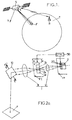
- the camera comprises a shooting optics 1, a matrix 2 of photodetectors 20, and several color filters, for example four 3a-3d filters.
- the shooting optics 1 may be of any type that is operational in the entire visible light band and beyond, for example between 360 nm and 950 nm. It may comprise an input optic 11 forming a radiation collector and a refocusing optic 12, with an intermediate focusing plane which is noted as PI.
- optics 11 and 12 are represented by simplicity in the form of lenses, but it is understood that it is most often mirrors. In general, the optics 11 and 12 each have a complex structure with several reflective and / or refractive components.
- the input optics 11 is a telescope, which may be of any type used in the field of spatial imaging.
- the photodetectors 20 are sensitive throughout the spectral band of observation, between 360 nm and 950 nm.
- the matrix 2 may be rectangular or square, for example 1024 ⁇ 1024 photodetectors.
- the photodetectors 20 are arranged in rows and columns which are juxtaposed in two perpendicular directions.
- the matrix 2 is placed in the focal plane PF of the optics 1.
- the pointing of the camera towards the land surface portion F can be achieved in several ways.
- the satellite S can be rotated as a whole to bring an optical axis of sight of the instrument to a central point of the portion F.
- Another method is to mount the instrument on an intermediate support which is orientable relative to the main platform of the satellite S. The pointing of the instrument is then achieved by actuating the orientation mechanism of the intermediate support.
- Yet another method is to arrange a steerable mirror 10 in front of the entrance of the shooting optics 1, and to adjust the orientation of the mirror 10 so that light rays originating from the land surface portion F are reflected by this mirror 10 to the input optic 11.
- a multiple image sequence can be acquired by the so-called "push-broom” method, known to those skilled in the art.
- the scrolling of the satellite S over the ground is used to scan the surface of the Earth perpendicular to the speed V of the satellite.
- the camera may further comprise a coding and transmission module, more simply designated by transmitter (not shown), for transmitting data corresponding to the captured images to a receiver R of a reception station located on Earth ( figure 1 ). These transmitted data are obtained from reading signals of the photodetectors 20. The receiver R then delivers these intermediate image data to an image reconstruction unit (not shown).
- a coding and transmission module more simply designated by transmitter (not shown) for transmitting data corresponding to the captured images to a receiver R of a reception station located on Earth ( figure 1 ). These transmitted data are obtained from reading signals of the photodetectors 20.
- the receiver R then delivers these intermediate image data to an image reconstruction unit (not shown).
- edges of the matrix 2 of the photodetectors 20 determine the peripheral boundary of the terrestrial surface portion F which is photographed at each exposure.
- a field diaphragm which is placed in the intermediate focusing plane PI can determine this limit of the portion F.
- a polychrome image of the terrestrial surface portion F can be obtained from several monochrome images of this same portion, by superimposing the latter.
- each monochrome image called intermediate image
- each monochrome image is captured for a different spectral subband which is included in the observation band, through a filter which determines this subband.
- filters may be placed in the path of the light rays arriving on the array 2 through the shooting optics 1. These filters may be located in the intermediate focusing plane P1, as shown, but it may be preferable to place them outside this plane, especially in a pupil plane or near a matrix of photodetectors which is used.
- the filter 3a can determine a spectral sub-band corresponding to the blue color, from 450 to 500 nm, the filter 3b can determine another sub-band corresponding to the green color, from 520 to 560 nm, the filter 3c still another sub-band corresponding to the yellow color, from 570 to 630 nm, and the filter 3d to a last sub-band which corresponds to the red color, from 640 to 680 nm.
- the invention can be implemented with any number n of spectral subbands within the observation band, where n is an integer that is greater than or equal to two.
- Each spectral subband preferably has a width that is less than 100 nm, or even less than 60 nm. Such a sub-band is spectrally narrow, so that the corresponding intermediate image is considered to be monochrome or quasi-monochrome.
- one of the spectral subbands is limited to shorter wavelengths with respect to at least one other of the subbands, within the spectral band of observation.
- the sub-band which is limited to shorter wavelengths is called the first spectral sub-band in the general part of this description, and the other sub-band is said to be extended towards the long wavelengths.
- the first subband contains the green color, i.e. the wavelength 550 nm.
- this first subband is between 400 and 600 nm, preferably between 510 and 570 nm. This may be the spectral range that extends from 520 nm to 560 nm, introduced previously for the filter 3b.
- the subband which is extended towards the long wavelengths can contain the wavelength 650 nm, corresponding to the red color. It can be the spectral range of the 3d filter. These two subbands spectral, with one that is more limited than the other on the side of large wavelength values, is the minimal structure of spectral subbands that is required to apply the invention. It may be supplemented by any additional spectral sub-band (s) within the observation band, such that one and / or the other of the intervals spectral filters 3a and 3c.
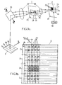
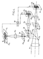
- the Figures 2a , 3a and 4 show three alternative optical configurations, to arrange the 3a-3d filters in the shooting optics 1. These configurations are equivalent in principle for the implementation of the invention, when the matrix (s) of photodetectors 20 is (are) used or selected appropriately, as will be described later.
- the filters 3a-3d can be arranged alternately in the path of the light rays that reach the matrix 2. Only one of these filters simultaneously affects the radiation that is received by all the photodetectors 20.
- the filters 3a-3d can then be exchanged , so that intermediate images are seized successively by the matrix 2 with each filter, for the same portion of terrestrial surface F.
- a mechanism known to those skilled in the art is actuated between two intermediate image captures, to replace one of the filters 3a-3d by another.
- each intermediate image that is captured can cover all the photodetectors 20 of the array 2.
- the image of this diaphragm on the array 2 defines an outline thereon, and each intermediate image covers all the photodetectors 20 of the matrix 2 which are located inside this contour, for each of the spectral subbands.
- the filters 3a-3d are fixed and arranged simultaneously in the intermediate focusing plane PI, forming a partition of the view of the portion F which is formed in this plane by the input optic 11.
- This partition is reproduced on the matrix 2 by the refocusing optics 12, so that the matrix 2 appears divided into separate portions 2a-2d which are dedicated respectively to the filters 3a-3d.
- the portion 2a of the matrix 2 collects the radiation of the blue sub-band
- the portion 2b collects the radiation of the green sub-band
- the portion 2c collects the radiation of the yellow sub-band.
- the 2d portion collects the radiation of the sub-band of red color.
- the filters 3a-3d have identical dimensions, so that the portions 2a-2d also have identical dimensions inside the matrix 2.
- the contours of the portions 2a-2d of the matrix 2 are then determined by those of the 3a-3d filters.
- different portions Fa-Fd of the terrestrial surface, inside the portion F are respectively imaged on the portions 2a-2d of the matrix 2.
- the scrolling of the satellite S produces a scan B which shifts the views of the land surface portions Fa-Fd relative to the matrix portions 2a-2d.
- the view of the terrestrial surface portion Fd is brought to the matrix portion 2c for a second exposure, then to the matrix portion 2b for a third exposure, and finally to the matrix portion 2a for a fourth exposure.
- Each of the exposures thus produces an intermediate image of the terrestrial surface portion Fd, through another of the 3a-3d filters.
- each intermediate image covers all the photodetectors 20 of the matrix 2 within the contour of the corresponding matrix portion 2a-2d.
- the third configuration that is represented in the figure 4 comprises separate optical channels which are dedicated respectively to the spectral subbands.
- the optical channel which is dedicated to the yellow sub-band has not been represented, but it is identical in principle to that which is dedicated to the red color.
- the input optics 11 may be common to all the channels, which are then separated by semi-reflective plates 13 1 and 13 2 or dichroic separators.
- the focal plane PF is multiplied, with the photodetector matrices 2 1 , 2 2 and 2 3 which are respectively located in the focal planes PF 1 , PF 2 and PF 3 .
- the filters 3a, 3b and 3d are fixed and located in the intermediate focusing planes PI 1 , PI 2 and PI 3 , with refocusing optics 12 1 , 12 2 and 12 3 for conjugating each intermediate focusing plane with the focal plane corresponding.
- all the photodetector matrices are controlled to simultaneously capture the intermediate images of the same portion of terrestrial surface F for all the sub-bands used.
- each of the photodetector matrices is of the TDI type, and each intermediate image is captured according to accumulation and reading phases which are combined with progressive displacements of the views of the scene F with respect to the matrices, in each of the focal plans.
- each filter which determines one of the spectral sub-bands affects all the phodetectors 20 which are used to capture the corresponding intermediate image, continuously extending between points of the concerned view which are imaged on these photodetectors.
- This configuration of the filters is opposed to the case of elementary filters of different colors which are associated with photodetectors adjacent to the same matrix of photodetectors, according to a distribution pattern of these elementary filters.
- a control unit 30 which is denoted CTRL, controls the capture of the intermediate images by the matrix (s) of photodetectors. Their order is synchronized, as the case may be, with an exchange of filters ( figure 2a ), the scrolling of the satellite S or a variation of the orientation of the mirror 10 ( figure 2b ).
- the photodetector matrix 20 which is used to capture the intermediate image for the first spectral subband, preferably corresponding to the green color, determines a Nyquist frequency ⁇ Nb .
- This frequency of Nyquist is equal to 1 / (2 xp b ), where p b is the step of the photodetectors 20 of the matrix which carries out the sampling of the view associated with the filter 3b.
- the Nyquist frequency ⁇ Nb is equal to 1 / (2 x GSD).
- each view that is formed by the optics 1 contains only the corresponding image information. at spatial frequencies that are less than a cutoff frequency.
- a shooting optics has a pupil which is at the origin of the filtering of the spatial image frequencies which are transmitted by this optics.
- the cutoff frequency of this low pass filtering of optics is an increasing function of the pupil dimension.
- the pupil of the shooting optics 1 is fixed by the telescope 11, which is the most bulky optical component of this optics. More precisely, it is the entrance mirror of the telescope 11 which most often limits the pupil, by the value of its diameter.
- the cutoff frequency that is thus produced by the telescope 11 depends on the spectral subband of the filtered radiation that produces the concerned view. Since the cutoff frequency of optics 1 is a decreasing function of the radiation wavelength, the cutoff frequency of optics 1, for each of the spectral subbands, depends on the upper limit of this one. subband. Thus, the cutoff frequency ⁇ Cb of the optics 1 for the first sub-band which contains the green color, is greater than the cutoff frequency ⁇ Cc or ⁇ Cd for one of the sub-bands which contains the yellow color (filter 3c) or the red color (3d filter).
- a shooting optics is dimensioned so that its cutoff spatial frequency ⁇ Ci , for each spectral subband i that is used, does not limit by itself the image information more than the sampling that is performed by the photodetectors that are used for this spectral subband.
- the skilled person usually chooses the size of the pupil of the optics for shooting so that its cutoff frequency is greater than the Nyquist frequency for the entire spectral band of observation.
- the optic 1 is selected to satisfy this condition for the first spectral subband, which corresponds to the green color of the filter 3b: ⁇ Nb ⁇ Cb .
- the optic 1 is further selected so that its cutoff spatial frequency for at least one other sub-band which contains a longer wavelength than the green color is less than the Nyquist frequency for the green color. For example: ⁇ Cd ⁇ Nb ⁇ Cb , where Cd is the cutoff spatial frequency of optics 1 for the red color of the 3d filter. In this way, the red-colored image information contained in the corresponding view is limited by the optics 1, but this optics has dimensions that are substantially reduced.
- the intermediate image corresponding to the red sub-band is acquired with the condition ⁇ Cd ⁇ Nb , it is not necessary for the Nyquist frequency for this red sub-band to be equal to that for the sub-band. green band.
- the intermediate image of the red sub-band can be acquired with a resolution which is greater or less fine than the resolution of the intermediate image of the green sub-band. Since the views are formed by the same optics 1 for all spectral subbands, the sampling of the view for the red sub-band may be smaller than that for the green sub-band.
- the intermediate image captured for the first spectral subband, green is formed using a corresponding sampling step of the corresponding view, which is twice as small as another sampling step used to capture the intermediate image of another spectral sub-band more extended towards the long wavelengths, for example red.
- Each array of photodetectors 20 is formed of L DET lines and C DET columns of photodetectors which are adjacent, and all the sampling steps which are considered are measured parallel to these lines and columns of photodetectors.
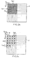
- the Figures 2b and 2c illustrate the first method for configuring the figure 2a , when the same matrix 2 is used to capture all the intermediate images. They represent this matrix 2, with each box being a photodetector 20.
- the photodetectors 20 which are marked with a cross are used to capture the intermediate image of the corresponding view, and those which are not marked with 'a cross are not used, that is to say that the intensity values they enter are not transmitted.
- the figure 2b corresponds to the use of the matrix 2 for the green sub-band of the filter 3b: all the photodetectors 20 are used.
- the Figure 2c corresponds to the use of the same matrix 2 for the yellow sub-band of the filter 3c or the red sub-band of the 3d filter: the photodetectors 20 which are used are restricted to a selection of one out of two along the lines L DET and columns C DET .
- the sampling for the green spectral subband corresponds to a surface density which is four times larger than the sampling for the yellow and red spectral subbands.
- p b is the sampling pitch for the green color
- p c / d is the yellow or red color.
- One advantage of this method of capturing the intermediate images other than that associated with the green color, by using only one photodetector 20 out of four, is to reduce the cross-talk which can occur between photodetectors 20 which are adjacent in the matrix 2. This results in an improvement of the contribution of the photodetectors in the total modulation transfer function of the camera.
- the figure 3b illustrates a transposition of this first intermediate image capture method for the configuration of the figure 3a .
- all the photodetectors 20 are read inside the portion 2b, corresponding to the filter 3b of the green sub-band, and only one photodetector 20 out of four is read or transmitted. inside the portions 2a, 2c and 2d corresponding to the other subbands.
- the second method of capturing intermediate images is applicable when separate photodetector arrays are used for subbands that are different, as in the configuration of the figure 4 .
- the sampling steps are identical to the individual widths of the L DET lines and the C DET columns of photodetectors of these matrices.
- the sampling of the view for the green sub-band then still corresponds to a surface density which is four times larger than the sampling of the view for the red spectral subband.
- the sampling of the view for the first spectral sub-band preferably corresponds to a surface density which is four times larger than the sampling of the view for the spectral subband which is more extensive towards the larger values. wavelength.
- an intermediate image is also entered for the spectral sub-band corresponding to the blue color, it is preferably captured using the same sampling step as for the yellow or red sub-band, ie say twice as big as the one used to capture the intermediate image of the green sub-band.
- the intermediate images of the blue, yellow and red colors each correspond to four times less image data than the intermediate image of the green color.
- a transmission time between the transmitter that is on board the satellite S and the terrestrial receiver R ( figure 1 ), for a polychrome final image is reduced compared to the case where all the intermediate images, monochrome, would have the same resolution, that is to say that which is associated with the green color.
- the intermediate image data that is transmitted between the transmitter and the receiver for the first spectral subband corresponds to four times more photodetector reading signals than the intermediate image data that is transmitted for the subframe.
- spectral band extended to long wavelengths, for the same scene that is captured in all spectral subbands.
- the image reconstruction unit then merges the intermediate images of all the spectral subbands, to obtain the final polychrome image.
- Image fusion methods that are known to those skilled in the art can be used.
- the final image then has the finest resolution among the respective resolutions of all the intermediate images.
- the final image has the resolution of the intermediate image that is associated with the green color.
- the polychrome visual rendering of this reconstructed final image which is provided by the other colors, appears consistent with its resolution because the green color corresponds substantially to the maximum of the spectral sensitivity of the human eye.
Landscapes
- Physics & Mathematics (AREA)
- General Physics & Mathematics (AREA)
- Optics & Photonics (AREA)
- Engineering & Computer Science (AREA)
- Multimedia (AREA)
- Signal Processing (AREA)
- Color Television Image Signal Generators (AREA)
Claims (17)
- Polychromatisches Bildgebungsverfahren in der spektralen Beobachtungsbandbreite von 360 nm bis 950 nm, umfassend die folgenden Schritte:/1/ das Mitführen einer Ansichtenaufnahmeoptik (1) an Bord eines Flugzeugs oder eines Satelliten (S), wobei die Ansichtenaufnahmeoptik ein Teleskop (11) umfasst und ausgestaltet ist, Ansichten in zumindest einer Fokalebene (PF) jeweils anhand von Strahlungen auszubilden, die zu mehreren spektralen Subbandbreiten gehören, die jede in der spektralen Beobachtungsbandbreite enthalten sind;/2/ das Anordnen zumindest einer Matrix (21, ..., 2n) von Photodetektoren (20) in der zumindest einen Fokalebene, um ein Zwischenbild jeder durch die Ansichtenaufnahmeoptik gebildeten Ansicht mit einer dem Zwischenbild zugeordneten Auflösung zu erfassen;/3/ das Erfassen der Zwischenbilder einer gleichen Szene (F) jeweils für jede spektrale Subbandbreite und/4/ das Vereinigen der jeweils für die spektralen Subbandbreiten erfassten Zwischenbilder, um ein polychromatisches Endbild auszubilden,wobei das Teleskop (11) der Ansichtenaufnahmeoptik (1) eine gemeinsame Pupille der spektralen Subbandbreiten bestimmt und eine Abmessung der gemeinsamen Pupille eine für jede spektrale Subbandbreite unterschiedliche Grenzortsfrequenz vorgibt,
wobei die spektralen Subbandbreiten eine erste spektrale Subbandbreite und zumindest eine weitere, sich hin zu den großen Wellenlängen erstreckende spektrale Subbandbreite umfassen, wobei die weitere, sich hin zu den großen Wellenlängen erstreckende spektrale Subbandbreite zumindest eine Wellenlänge aufweist, die größer ist als ein oberer Grenzwert der ersten spektralen Subbandbreite, wobei die Pupille des Teleskops (11) so dimensioniert ist, dass die Grenzortsfrequenz für die erste spektrale Subbandbreite größer ist als die Nyquist-Frequenz des für die erste spektrale Subbandbreite erfassten Zwischenbilds,
wobei jede spektrale Subbandbreite durch einen einzigen Filter (3a - 3d) bestimmt wird, der alle für die Erfassung des entsprechenden Zwischenbilds genutzten Photodetektoren (20) betrifft, indem er sich kontinuierlich zwischen Punkten der betreffenden Ansicht, die auf diesen Photodetektoren abgebildet sind, erstreckt,
wobei das Verfahren dadurch gekennzeichnet ist, dass die Pupille des Teleskops (11) ferner so dimensioniert ist, dass die Grenzortsfrequenz für die weitere, sich hin zu den großen Wellenlängen erstreckende spektrale Subbandbreite kleiner ist als die Nyquist-Frequenz des für die erste spektrale Subbandbreite erfassten Zwischenbilds,
und dadurch, dass das für die erste spektrale Subbandbreite erfasste Zwischenbild gebildet wird, indem ein Abtastschritt (pb) der entsprechenden Ansicht genutzt wird, der halb so groß ist wie ein weiterer Abtastschritt (pd), der für die Erfassung des Zwischenbilds der weiteren, sich hin zu den großen Wellenlängen erstreckenden spektralen Subbandbreite genutzt wird, wobei die Abtastschritte parallel zu Zeilen (LDET) und Spalten (CDET) der Photodetektoren (20) so gemessen werden, dass die Abtastung für die erste spektrale Subbandbreite einer viermal größeren Flächendichte als die Abtastung für die weitere, sich hin zu den großen Wellenlängen erstreckende spektrale Subbandbreite entspricht. - Verfahren nach Anspruch 1, wobei die erste spektrale Subbandbreite die Wellenlänge 550 nm umfasst.
- Verfahren nach Anspruch 1 oder 2, wobei das polychromatische Endbild eine Auflösung aufweist, die gleich der Auflösung des für die erste spektrale Subbandbreite erfassten Zwischenbilds ist.
- Verfahren nach einem der vorangehenden Ansprüche, wobei die erste spektrale Subbandbreite einer grünen Farbe entspricht, die weitere, sich hin zu den großen Wellenlängen erstreckende spektrale Subbandbreite einer roten Farbe entspricht und noch eine weitere spektrale Subbandbreite einer blauen Farbe entspricht.
- Verfahren nach einem der vorangehenden Ansprüche, wobei die Zeilen (LDET) und die Spalten (CDET) der Photodetektoren (20) in jeder genutzten Photodetektorenmatrix (2) aneinander angrenzen und wobei das für die erste spektrale Subbandbreite erfasste Zwischenbild erhalten wird, indem alle Photodetektoren der für die erste spektrale Subbandbreite genutzten Matrix genutzt werden, und wobei das für die weitere, sich hin zu den großen Wellenlängen erstreckende spektrale Subbandbreite erfasste Zwischenbild erhalten wird, indem jeder zweite Photodetektor entlang der Zeilen und der Spalten der Photodetektoren der für die weitere spektrale Subbandbreite genutzten Matrix ausgewählt wird.
- Verfahren nach einem der Ansprüche 1 bis 4, wobei die Matrix (21) der Photodetektoren (20), die für die Erfassung des Zwischenbilds der ersten spektralen Subbandbreite genutzt wird, eine Breite der Zeilen (LDET) und Spalten (CDET) aufweist, die halb so groß ist wie eine Zeilen- und Spaltenbreite der Photodetektorenmatrix (23), die für die Erfassung des Zwischenbilds der weiteren, sich hin zu den großen Wellenlängen erstreckenden spektralen Subbandbreite genutzt wird.
- Verfahren nach Anspruch 4 und einem der vorangehenden Ansprüche, wobei das Zwischenbild, das für die spektrale Subbandbreite, die der blauen Farbe entspricht, erfasst wurde, auf demselben Abtastschritt (pd) wie für die weitere, sich hin zu den großen Wellenlängen erstreckende spektrale Subbandbreite, die der roten Farbe entspricht, und auf dem Doppelten des Abtastschritts (pb), der für die Erfassung des Zwischenbilds der ersten spektralen Subbandbreite, die der grünen Farbe entspricht, genutzt wird, basiert.
- Verfahren nach einem der vorangehenden Ansprüche, wobei die Szene (F), deren Zwischenbilder in Schritt /3/ erfasst werden, ein Oberflächenabschnitt der Erde (T) ist.
- Verfahren nach einem der vorangehenden Ansprüche, wobei die Zwischenbilddaten für jede spektrale Subbandbreite zwischen dem Flugzeug bzw. dem Satelliten (S) und einer Empfangsstation (R) übertragen werden, wobei für dieselbe, in allen spektralen Subbandbreiten erfasste Szene (F) die für die erste spektrale Subbandbreite übertragenen Zwischenbilddaten viermal mehr Lesesignalen von Photodetektoren (20) entsprechen als die für die weitere, sich hin zu den großen Wellenlängen erstreckende spektrale Subbandbreite übertragenen Zwischenbilddaten.
- Polychromatisches Bildgebungssystem, das für die Mitführung an Bord eines Flugzeugs oder eines Satelliten (S) ausgestaltet ist, umfassend:- eine Ansichtenaufnahmeoptik (1), die ein Teleskop (11) umfasst und ausgestaltet ist, Ansichten in zumindest einer Fokalebene (PF) jeweils anhand von Strahlungen auszubilden, die zu spektralen Subbandbreiten gehören, die jede in der spektralen Beobachtungsbandbreite von 360 nm bis 950 nm enthalten sind;- zumindest eine Matrix (21, ..., 2n) von Photodetektoren (20), die in der zumindest einen Fokalebene angeordnet und ausgestaltet ist, ein Zwischenbild jeder Ansicht mit einer dem Zwischenbild zugeordneten Auflösung zu erfassen;- eine Steuerungseinheit (30), die ausgestaltet ist, eine Erfassung der Zwischenbilder einer gleichen Szene (F) jeweils für jede spektrale Subbandbreite zu steuern; und- eine Bildwiederherstellungseinheit, die ausgestaltet ist, die jeweils für die spektralen Subbandbreiten erfassten Zwischenbilder zu vereinigen, um ein polychromatisches Endbild auszubilden,wobei das Teleskop (11) der Ansichtenaufnahmeoptik (1) eine gemeinsame Pupille der spektralen Subbandbreiten bestimmt und wobei eine Abmessung der gemeinsamen Pupille eine für jede spektrale Subbandbreite unterschiedliche Grenzortsfrequenz vorgibt,
wobei das System ausgestaltet ist, eine erste der spektralen Subbandbreiten und eine weitere der spektralen Subbandbreiten, die sich hin zu den großen Wellenlängen erstreckt, vorzugeben, wobei die weitere, sich hin zu den großen Wellenlängen erstreckende spektrale Subbandbreite zumindest eine Wellenlänge aufweist, die größer ist als ein oberer Grenzwert der ersten spektralen Subbandbreite, wobei die Pupille des Teleskops (11) so dimensioniert ist, dass die Grenzortsfrequenz für die erste spektrale Subbandbreite größer ist als die Nyquist-Frequenz des für die erste spektrale Subbandbreite erfassten Zwischenbilds,
wobei jede spektrale Subbandbreite durch einen einzigen Filter (3a - 3d) bestimmt wird, der alle für die Erfassung des entsprechenden Zwischenbilds genutzten Photodetektoren (20) betrifft, indem er sich kontinuierlich zwischen Punkten der betreffenden Ansicht, die auf diesen Photodetektoren abgebildet sind, erstreckt,
wobei das System dadurch gekennzeichnet ist, dass die Pupille des Teleskops (11) ferner so dimensioniert ist, dass die Grenzortsfrequenz für die weitere, sich hin zu den großen Wellenlängen erstreckende spektrale Subbandbreite kleiner ist als die Nyquist-Frequenz des für die erste spektrale Subbandbreite erfassten Zwischenbilds,
und dadurch, dass das System ferner ausgestaltet ist, die Zwischenbilder in Abhängigkeit von Abtastschritten der entsprechenden Ansichten jeweils für die spektralen Subbandbreiten zu erfassen, wobei der Abtastschritt (pb), der für die erste spektrale Subbandbreite genutzt wird, halb so groß ist wie der Abtastschritt (pd), der für die Erfassung des Zwischenbilds der weiteren, sich hin zu den großen Wellenlängen erstreckenden spektralen Subbandbreite genutzt wird, wobei die Abtastschritte parallel zu Zeilen (LDET) und Spalten (CDET) der Photodetektoren (20) so gemessen werden, dass die Abtastung für die erste spektrale Subbandbreite einer viermal größeren Flächendichte als die Abtastung für die weitere, sich hin zu den großen Wellenlängen erstreckende spektrale Subbandbreite entspricht. - System nach Anspruch 10, das derart ausgestaltet ist, dass die erste spektrale Subbandbreite die Wellenlänge 550 nm umfasst.
- System nach Anspruch 10 oder 11, wobei die Bildwiederherstellungseinheit derart ausgestaltet ist, dass das polychromatische Endbild eine Auflösung aufweist, die gleich der Auflösung des für die erste spektrale Subbandbreite erfassten Zwischenbilds ist.
- System nach einem der Ansprüche 10 bis 12, das derart ausgestaltet ist, dass die erste spektrale Subbandbreite einer grünen Farbe entspricht, die weitere, sich hin zu den großen Wellenlängen erstreckende spektrale Subbandbreite einer roten Farbe entspricht und noch eine weitere spektrale Subbandbreite einer blauen Farbe entspricht.
- System nach einem der Ansprüche 10 bis 13, wobei die Zeilen (LDET) und die Spalten (CDET) der Photodetektoren (20) in jeder Photodetektorenmatrix (2) aneinander angrenzen und wobei die Steuerungseinheit (30) ausgestaltet ist, das Zwischenbild für die erste spektrale Subbandbreite zu erfassen, indem alle Photodetektoren der für die erste spektrale Subbandbreite genutzten Matrix genutzt werden, und das Zwischenbild für die weitere, sich hin zu den großen Wellenlängen erstreckende spektrale Subbandbreite zu erfassen, indem jeder zweite Photodetektor entlang der Zeilen und Spalten der Photodetektoren der für die weitere spektrale Subbandbreite genutzten Matrix ausgewählt wird.
- System nach einem der Ansprüche 10 bis 13, wobei die Photodetektorenmatrix (21), die für die Erfassung des Zwischenbilds der ersten spektralen Subbandbreite genutzt wird, eine Breite der Zeilen (LDET) und Spalten (CDET) aufweist, die halb so groß ist wie eine Zeilen- und Spaltenbreite der Photodetektorenmatrix (23), die für die Erfassung des Zwischenbilds der weiteren, sich hin zu den großen Wellenlängen erstreckenden spektralen Subbandbreite genutzt wird.
- System nach Anspruch 13 und einem der Ansprüche 10 bis 15, das ausgestaltet ist, das Zwischenbild der spektralen Subbandbreite, die der blauen Farbe entspricht, zu erfassen, indem derselbe Abtastschritt (pd) wie für die weitere, sich hin zu den großen Wellenlängen erstreckende spektrale Subbandbreite, die der roten Farbe entspricht, und das Doppelte des Abtastschritts (pb), der für die Erfassung des Zwischenbilds der ersten spektralen Subbandbreite, die der grünen Farbe entspricht, genutzt wird.
- System nach einem der Ansprüche 10 bis 16, ferner umfassend:- einen Sender, der angeordnet ist, Zwischenbilddaten für jede spektrale Subbandbreite anhand von Lesesignalen der Photodetektoren (20) zu übertragen; und- einen Empfänger, der angeordnet ist, die vom Sender übertragenen Zwischenbilddaten zu empfangen und die Zwischenbilddaten der Bildwiederherstellungseinheit bereitzustellen,wobei das System derart ausgestaltet ist, dass für dieselbe, in allen spektralen Subbandbreiten erfasste Szene (F) die zwischen dem Sender und dem Empfänger (R) für die erste spektrale Subbandbreite übertragenen Zwischenbilddaten viermal mehr Lesesignalen von Photodetektoren (20) entsprechen als die für die weitere, sich hin zu den großen Wellenlängen erstreckende spektrale Subbandbreite übertragenen Zwischenbilddaten.
Applications Claiming Priority (2)
| Application Number | Priority Date | Filing Date | Title |
|---|---|---|---|
| FR1053450A FR2959903B1 (fr) | 2010-05-04 | 2010-05-04 | Procede d'imagerie polychrome |
| PCT/FR2011/050977 WO2011138541A1 (fr) | 2010-05-04 | 2011-04-28 | Procede d'imagerie polychrome |
Publications (2)
| Publication Number | Publication Date |
|---|---|
| EP2567537A1 EP2567537A1 (de) | 2013-03-13 |
| EP2567537B1 true EP2567537B1 (de) | 2015-11-25 |
Family
ID=43501526
Family Applications (1)
| Application Number | Title | Priority Date | Filing Date |
|---|---|---|---|
| EP11723533.3A Active EP2567537B1 (de) | 2010-05-04 | 2011-04-28 | Polychromatisches bildgebungsverfahren |
Country Status (5)
| Country | Link |
|---|---|
| US (1) | US9055240B2 (de) |
| EP (1) | EP2567537B1 (de) |
| ES (1) | ES2563206T3 (de) |
| FR (1) | FR2959903B1 (de) |
| WO (1) | WO2011138541A1 (de) |
Families Citing this family (18)
| Publication number | Priority date | Publication date | Assignee | Title |
|---|---|---|---|---|
| US9442012B2 (en) | 2011-04-25 | 2016-09-13 | Skybox Imaging, Inc. | Systems and methods for overhead imaging and video |
| US9020336B1 (en) * | 2012-05-29 | 2015-04-28 | Cordin Company, Inc. | Digital streak camera with rotating mirror |
| FR3005226B1 (fr) * | 2013-04-25 | 2015-04-10 | Astrium Sas | Saisie d'image avec addition de signaux d'accumulation pour des photodetecteurs adjacents |
| WO2015192056A1 (en) | 2014-06-13 | 2015-12-17 | Urthecast Corp. | Systems and methods for processing and providing terrestrial and/or space-based earth observation video |
| US11300449B2 (en) | 2015-03-24 | 2022-04-12 | University Of Utah Research Foundation | Imaging device with image dispersing to create a spatially coded image |
| WO2016153914A1 (en) | 2015-03-25 | 2016-09-29 | King Abdulaziz City Of Science And Technology | Apparatus and methods for synthetic aperture radar with digital beamforming |
| WO2017044168A2 (en) | 2015-06-16 | 2017-03-16 | King Abdulaziz City Of Science And Technology | Efficient planar phased array antenna assembly |
| US10955546B2 (en) | 2015-11-25 | 2021-03-23 | Urthecast Corp. | Synthetic aperture radar imaging apparatus and methods |
| CN122234523A (zh) | 2017-04-14 | 2026-06-19 | 埃克森美孚化学专利公司 | 包含epdm和epr的弹性体组合物 |
| EP3631504B8 (de) | 2017-05-23 | 2023-08-16 | Spacealpha Insights Corp. | Radarbildgebungsvorrichtung mit synthetischer apertur und verfahren |
| CA3064586A1 (en) | 2017-05-23 | 2018-11-29 | King Abdullah City Of Science And Technology | Synthetic aperture radar imaging apparatus and methods for moving targets |
| US11525910B2 (en) | 2017-11-22 | 2022-12-13 | Spacealpha Insights Corp. | Synthetic aperture radar apparatus and methods |
| WO2019112728A1 (en) | 2017-12-08 | 2019-06-13 | Exxonmobil Chemical Patents Inc. | Elastomeric terpolymer compositions for corner molding applications |
| EP3768734B1 (de) | 2018-03-19 | 2025-10-22 | ExxonMobil Chemical Patents Inc. | Elastomere propylen-alpha-olefin-dien-terpolymer-zusammensetzungen |
| FR3090134B1 (fr) * | 2018-12-18 | 2020-11-20 | Thales Sa | Système de datation de grande précision de passage d’un objet, notamment d’un satellite |
| WO2021011906A1 (en) | 2019-07-17 | 2021-01-21 | Exxonmobil Chemical Patents Inc. | TIRES COMPRISING RUBBER COMPOUNDS THAT COMPRISE PROPYLENE-α-OLEFIN-DIENE POLYMERS |
| US12157582B2 (en) * | 2019-11-29 | 2024-12-03 | Mitsubishi Heavy Industries, Ltd. | Observation control device and spacecraft, observation control method, and observation control program |
| FR3132151B1 (fr) * | 2022-01-26 | 2024-01-12 | Airbus Defence & Space Sas | Instrument d’imagerie |
Family Cites Families (14)
| Publication number | Priority date | Publication date | Assignee | Title |
|---|---|---|---|---|
| US3971065A (en) | 1975-03-05 | 1976-07-20 | Eastman Kodak Company | Color imaging array |
| US5276321A (en) * | 1991-04-15 | 1994-01-04 | Geophysical & Environmental Research Corp. | Airborne multiband imaging spectrometer |
| JP2861525B2 (ja) * | 1991-09-10 | 1999-02-24 | 松下電器産業株式会社 | 波長選択性位相格子光学的ローパスフィルタ |
| US5841574A (en) * | 1996-06-28 | 1998-11-24 | Recon/Optical, Inc. | Multi-special decentered catadioptric optical system |
| US6009340A (en) * | 1998-03-16 | 1999-12-28 | Northrop Grumman Corporation | Multimode, multispectral imaging system |
| CA2445044C (en) * | 2001-04-25 | 2011-02-15 | Amnis Corporation | Method and apparatus for correcting crosstalk and spatial resolution for multichannel imaging |
| US7049597B2 (en) * | 2001-12-21 | 2006-05-23 | Andrew Bodkin | Multi-mode optical imager |
| EP1812968B1 (de) * | 2004-08-25 | 2019-01-16 | Callahan Cellular L.L.C. | Vorrichtung für mehrere kameraeinrichtungen und verfahren zu ihrem betrieb |
| US20090051984A1 (en) | 2007-08-23 | 2009-02-26 | O'brien Michele | Image sensor having checkerboard pattern |
| US8149319B2 (en) * | 2007-12-03 | 2012-04-03 | Ricoh Co., Ltd. | End-to-end design of electro-optic imaging systems for color-correlated objects |
| EP2175416A1 (de) * | 2008-10-13 | 2010-04-14 | Sony Corporation | Verfahren und System zur Bildscharfstellung |
| US8558182B2 (en) * | 2009-10-09 | 2013-10-15 | University Of Rochester | Optical element, device, method, and applications |
| WO2011153515A1 (en) * | 2010-06-03 | 2011-12-08 | Tripurari Singh | Methods and system for spectral image sampling |
| CN102982517B (zh) * | 2012-11-02 | 2015-03-25 | 武汉大学 | 基于光谱与空间局部相关的遥感影像融合方法 |
-
2010
- 2010-05-04 FR FR1053450A patent/FR2959903B1/fr active Active
-
2011
- 2011-04-28 WO PCT/FR2011/050977 patent/WO2011138541A1/fr not_active Ceased
- 2011-04-28 US US13/696,249 patent/US9055240B2/en active Active
- 2011-04-28 EP EP11723533.3A patent/EP2567537B1/de active Active
- 2011-04-28 ES ES11723533.3T patent/ES2563206T3/es active Active
Non-Patent Citations (1)
| Title |
|---|
| "KODAK KAI-2020 Rev 2.1 Device Performance Specification", 6 June 2005 (2005-06-06), pages 1 - 49, XP055144939, Retrieved from the Internet <URL:http://www.stargazing.net/david/QSI/KAI-2020LongSpec.pdf> [retrieved on 20141007] * |
Also Published As
| Publication number | Publication date |
|---|---|
| EP2567537A1 (de) | 2013-03-13 |
| ES2563206T3 (es) | 2016-03-11 |
| US20130050488A1 (en) | 2013-02-28 |
| WO2011138541A1 (fr) | 2011-11-10 |
| FR2959903B1 (fr) | 2012-07-27 |
| FR2959903A1 (fr) | 2011-11-11 |
| US9055240B2 (en) | 2015-06-09 |
Similar Documents
| Publication | Publication Date | Title |
|---|---|---|
| WO2011138541A1 (fr) | Procede d'imagerie polychrome | |
| EP2515335B1 (de) | Bildgebender integrierter Schaltkreis, und Vorrichtung zur Erfassung von Stereobildern | |
| CA2592293C (fr) | Procede de traitement d'images mettant en oeuvre le georeferencement automatique d'images issues d'un couple d'images pris dans le meme plan focal | |
| EP2735901B1 (de) | Bildgebungsgerät mit mehreren Erkennungseinheiten, die auf einer Brennebene angeordnet sind | |
| FR3021127A1 (fr) | Systeme et procede d'acquisition d'images hyperspectrales | |
| EP1472563B1 (de) | Satellitengestütztes optisches beobachtungsinstrument mit zwei teleskopen | |
| EP3777129B1 (de) | Luftbildsensor zur aufnahme von matrixbildern durch zeitliche verschiebung und multispektrale summation | |
| FR3107953A1 (fr) | Procédé d’acquisition d’images d’une zone terrestre par un engin spatial | |
| CA3038880C (fr) | Dispositif spectrophotometrique a plusieurs bandes spectrales de mesure | |
| WO2011138542A1 (fr) | Procede d'imagerie | |
| EP3916462B1 (de) | Optisches instrument mit teleskopfunktion und mehreren kanälen | |
| EP3839814B1 (de) | Bordseitiges optisches beobachtungsinstrument mit variabler räumlicher und spektraler auflösung | |
| EP2093602A1 (de) | Bildgebungsvorrichtung mit mehreren Strahlablenkern | |
| WO2020007795A1 (fr) | Viseur optronique et plate-forme associée | |
| CA3231635A1 (fr) | Procede pour l'acquisition d'images multispectrales et d'imagettes panchromatiques | |
| WO2016146830A1 (fr) | Capteur d'images polarimétriques | |
| EP1544667B1 (de) | Frequenzmässige Vervollständigung von Bildern, die mit einer Apparatur mit verdünnter synthetischer, optischer Apertur aufgenommen wurden, durch Kombination von Bildern, welche sich im Frequenzbereich ergänzen | |
| WO2024149666A1 (fr) | Système optique d'imagerie hyperspectrale | |
| EP3784998A1 (de) | Pupillenbildgebendes spektrometer | |
| FR3073295A1 (fr) | Telescope spatial generant des images couleur a deux formats grand champ et haute resolution | |
| EP2989787A1 (de) | Bilderfassung unter zugabe von akkumulationssignalen für benachbarte photodetektoren | |
| FR3132151A1 (fr) | Instrument d’imagerie |
Legal Events
| Date | Code | Title | Description |
|---|---|---|---|
| PUAI | Public reference made under article 153(3) epc to a published international application that has entered the european phase |
Free format text: ORIGINAL CODE: 0009012 |
|
| 17P | Request for examination filed |
Effective date: 20121023 |
|
| AK | Designated contracting states |
Kind code of ref document: A1 Designated state(s): AL AT BE BG CH CY CZ DE DK EE ES FI FR GB GR HR HU IE IS IT LI LT LU LV MC MK MT NL NO PL PT RO RS SE SI SK SM TR |
|
| RAP1 | Party data changed (applicant data changed or rights of an application transferred) |
Owner name: ASTRIUM SAS |
|
| DAX | Request for extension of the european patent (deleted) | ||
| 17Q | First examination report despatched |
Effective date: 20140326 |
|
| RAP1 | Party data changed (applicant data changed or rights of an application transferred) |
Owner name: AIRBUS DEFENCE AND SPACE SAS |
|
| GRAP | Despatch of communication of intention to grant a patent |
Free format text: ORIGINAL CODE: EPIDOSNIGR1 |
|
| INTG | Intention to grant announced |
Effective date: 20150722 |
|
| RIN1 | Information on inventor provided before grant (corrected) |
Inventor name: BROUARD, LAURENT Inventor name: TOURNEUR, CYRILLE |
|
| GRAS | Grant fee paid |
Free format text: ORIGINAL CODE: EPIDOSNIGR3 |
|
| GRAA | (expected) grant |
Free format text: ORIGINAL CODE: 0009210 |
|
| AK | Designated contracting states |
Kind code of ref document: B1 Designated state(s): AL AT BE BG CH CY CZ DE DK EE ES FI FR GB GR HR HU IE IS IT LI LT LU LV MC MK MT NL NO PL PT RO RS SE SI SK SM TR |
|
| REG | Reference to a national code |
Ref country code: GB Ref legal event code: FG4D Free format text: NOT ENGLISH |
|
| REG | Reference to a national code |
Ref country code: CH Ref legal event code: EP |
|
| REG | Reference to a national code |
Ref country code: AT Ref legal event code: REF Ref document number: 763092 Country of ref document: AT Kind code of ref document: T Effective date: 20151215 |
|
| REG | Reference to a national code |
Ref country code: IE Ref legal event code: FG4D Free format text: LANGUAGE OF EP DOCUMENT: FRENCH |
|
| REG | Reference to a national code |
Ref country code: DE Ref legal event code: R096 Ref document number: 602011021619 Country of ref document: DE |
|
| REG | Reference to a national code |
Ref country code: ES Ref legal event code: FG2A Ref document number: 2563206 Country of ref document: ES Kind code of ref document: T3 Effective date: 20160311 |
|
| REG | Reference to a national code |
Ref country code: LT Ref legal event code: MG4D |
|
| REG | Reference to a national code |
Ref country code: NL Ref legal event code: MP Effective date: 20160225 |
|
| REG | Reference to a national code |
Ref country code: AT Ref legal event code: MK05 Ref document number: 763092 Country of ref document: AT Kind code of ref document: T Effective date: 20151125 |
|
| REG | Reference to a national code |
Ref country code: FR Ref legal event code: PLFP Year of fee payment: 6 |
|
| PG25 | Lapsed in a contracting state [announced via postgrant information from national office to epo] |
Ref country code: HR Free format text: LAPSE BECAUSE OF FAILURE TO SUBMIT A TRANSLATION OF THE DESCRIPTION OR TO PAY THE FEE WITHIN THE PRESCRIBED TIME-LIMIT Effective date: 20151125 Ref country code: LT Free format text: LAPSE BECAUSE OF FAILURE TO SUBMIT A TRANSLATION OF THE DESCRIPTION OR TO PAY THE FEE WITHIN THE PRESCRIBED TIME-LIMIT Effective date: 20151125 Ref country code: IS Free format text: LAPSE BECAUSE OF FAILURE TO SUBMIT A TRANSLATION OF THE DESCRIPTION OR TO PAY THE FEE WITHIN THE PRESCRIBED TIME-LIMIT Effective date: 20160325 Ref country code: NO Free format text: LAPSE BECAUSE OF FAILURE TO SUBMIT A TRANSLATION OF THE DESCRIPTION OR TO PAY THE FEE WITHIN THE PRESCRIBED TIME-LIMIT Effective date: 20160225 Ref country code: NL Free format text: LAPSE BECAUSE OF FAILURE TO SUBMIT A TRANSLATION OF THE DESCRIPTION OR TO PAY THE FEE WITHIN THE PRESCRIBED TIME-LIMIT Effective date: 20151125 |
|
| PG25 | Lapsed in a contracting state [announced via postgrant information from national office to epo] |
Ref country code: GR Free format text: LAPSE BECAUSE OF FAILURE TO SUBMIT A TRANSLATION OF THE DESCRIPTION OR TO PAY THE FEE WITHIN THE PRESCRIBED TIME-LIMIT Effective date: 20160226 Ref country code: LV Free format text: LAPSE BECAUSE OF FAILURE TO SUBMIT A TRANSLATION OF THE DESCRIPTION OR TO PAY THE FEE WITHIN THE PRESCRIBED TIME-LIMIT Effective date: 20151125 Ref country code: SE Free format text: LAPSE BECAUSE OF FAILURE TO SUBMIT A TRANSLATION OF THE DESCRIPTION OR TO PAY THE FEE WITHIN THE PRESCRIBED TIME-LIMIT Effective date: 20151125 Ref country code: PL Free format text: LAPSE BECAUSE OF FAILURE TO SUBMIT A TRANSLATION OF THE DESCRIPTION OR TO PAY THE FEE WITHIN THE PRESCRIBED TIME-LIMIT Effective date: 20151125 Ref country code: PT Free format text: LAPSE BECAUSE OF FAILURE TO SUBMIT A TRANSLATION OF THE DESCRIPTION OR TO PAY THE FEE WITHIN THE PRESCRIBED TIME-LIMIT Effective date: 20160325 Ref country code: AT Free format text: LAPSE BECAUSE OF FAILURE TO SUBMIT A TRANSLATION OF THE DESCRIPTION OR TO PAY THE FEE WITHIN THE PRESCRIBED TIME-LIMIT Effective date: 20151125 Ref country code: RS Free format text: LAPSE BECAUSE OF FAILURE TO SUBMIT A TRANSLATION OF THE DESCRIPTION OR TO PAY THE FEE WITHIN THE PRESCRIBED TIME-LIMIT Effective date: 20151125 Ref country code: FI Free format text: LAPSE BECAUSE OF FAILURE TO SUBMIT A TRANSLATION OF THE DESCRIPTION OR TO PAY THE FEE WITHIN THE PRESCRIBED TIME-LIMIT Effective date: 20151125 |
|
| PG25 | Lapsed in a contracting state [announced via postgrant information from national office to epo] |
Ref country code: CZ Free format text: LAPSE BECAUSE OF FAILURE TO SUBMIT A TRANSLATION OF THE DESCRIPTION OR TO PAY THE FEE WITHIN THE PRESCRIBED TIME-LIMIT Effective date: 20151125 |
|
| REG | Reference to a national code |
Ref country code: DE Ref legal event code: R097 Ref document number: 602011021619 Country of ref document: DE |
|
| PG25 | Lapsed in a contracting state [announced via postgrant information from national office to epo] |
Ref country code: DK Free format text: LAPSE BECAUSE OF FAILURE TO SUBMIT A TRANSLATION OF THE DESCRIPTION OR TO PAY THE FEE WITHIN THE PRESCRIBED TIME-LIMIT Effective date: 20151125 Ref country code: SM Free format text: LAPSE BECAUSE OF FAILURE TO SUBMIT A TRANSLATION OF THE DESCRIPTION OR TO PAY THE FEE WITHIN THE PRESCRIBED TIME-LIMIT Effective date: 20151125 Ref country code: SK Free format text: LAPSE BECAUSE OF FAILURE TO SUBMIT A TRANSLATION OF THE DESCRIPTION OR TO PAY THE FEE WITHIN THE PRESCRIBED TIME-LIMIT Effective date: 20151125 Ref country code: EE Free format text: LAPSE BECAUSE OF FAILURE TO SUBMIT A TRANSLATION OF THE DESCRIPTION OR TO PAY THE FEE WITHIN THE PRESCRIBED TIME-LIMIT Effective date: 20151125 Ref country code: RO Free format text: LAPSE BECAUSE OF FAILURE TO SUBMIT A TRANSLATION OF THE DESCRIPTION OR TO PAY THE FEE WITHIN THE PRESCRIBED TIME-LIMIT Effective date: 20151125 Ref country code: BE Free format text: LAPSE BECAUSE OF NON-PAYMENT OF DUE FEES Effective date: 20160430 |
|
| PLBE | No opposition filed within time limit |
Free format text: ORIGINAL CODE: 0009261 |
|
| STAA | Information on the status of an ep patent application or granted ep patent |
Free format text: STATUS: NO OPPOSITION FILED WITHIN TIME LIMIT |
|
| 26N | No opposition filed |
Effective date: 20160826 |
|
| PG25 | Lapsed in a contracting state [announced via postgrant information from national office to epo] |
Ref country code: SI Free format text: LAPSE BECAUSE OF FAILURE TO SUBMIT A TRANSLATION OF THE DESCRIPTION OR TO PAY THE FEE WITHIN THE PRESCRIBED TIME-LIMIT Effective date: 20151125 |
|
| REG | Reference to a national code |
Ref country code: CH Ref legal event code: PL |
|
| PG25 | Lapsed in a contracting state [announced via postgrant information from national office to epo] |
Ref country code: LU Free format text: LAPSE BECAUSE OF FAILURE TO SUBMIT A TRANSLATION OF THE DESCRIPTION OR TO PAY THE FEE WITHIN THE PRESCRIBED TIME-LIMIT Effective date: 20160428 |
|
| REG | Reference to a national code |
Ref country code: IE Ref legal event code: MM4A |
|
| PG25 | Lapsed in a contracting state [announced via postgrant information from national office to epo] |
Ref country code: CH Free format text: LAPSE BECAUSE OF NON-PAYMENT OF DUE FEES Effective date: 20160430 Ref country code: LI Free format text: LAPSE BECAUSE OF NON-PAYMENT OF DUE FEES Effective date: 20160430 |
|
| REG | Reference to a national code |
Ref country code: FR Ref legal event code: PLFP Year of fee payment: 7 |
|
| PG25 | Lapsed in a contracting state [announced via postgrant information from national office to epo] |
Ref country code: IE Free format text: LAPSE BECAUSE OF NON-PAYMENT OF DUE FEES Effective date: 20160428 |
|
| REG | Reference to a national code |
Ref country code: FR Ref legal event code: PLFP Year of fee payment: 8 |
|
| PG25 | Lapsed in a contracting state [announced via postgrant information from national office to epo] |
Ref country code: HU Free format text: LAPSE BECAUSE OF FAILURE TO SUBMIT A TRANSLATION OF THE DESCRIPTION OR TO PAY THE FEE WITHIN THE PRESCRIBED TIME-LIMIT; INVALID AB INITIO Effective date: 20110428 Ref country code: CY Free format text: LAPSE BECAUSE OF FAILURE TO SUBMIT A TRANSLATION OF THE DESCRIPTION OR TO PAY THE FEE WITHIN THE PRESCRIBED TIME-LIMIT Effective date: 20151125 |
|
| PG25 | Lapsed in a contracting state [announced via postgrant information from national office to epo] |
Ref country code: TR Free format text: LAPSE BECAUSE OF FAILURE TO SUBMIT A TRANSLATION OF THE DESCRIPTION OR TO PAY THE FEE WITHIN THE PRESCRIBED TIME-LIMIT Effective date: 20151125 Ref country code: MK Free format text: LAPSE BECAUSE OF FAILURE TO SUBMIT A TRANSLATION OF THE DESCRIPTION OR TO PAY THE FEE WITHIN THE PRESCRIBED TIME-LIMIT Effective date: 20151125 Ref country code: MT Free format text: LAPSE BECAUSE OF FAILURE TO SUBMIT A TRANSLATION OF THE DESCRIPTION OR TO PAY THE FEE WITHIN THE PRESCRIBED TIME-LIMIT Effective date: 20151125 Ref country code: MC Free format text: LAPSE BECAUSE OF FAILURE TO SUBMIT A TRANSLATION OF THE DESCRIPTION OR TO PAY THE FEE WITHIN THE PRESCRIBED TIME-LIMIT Effective date: 20151125 |
|
| PG25 | Lapsed in a contracting state [announced via postgrant information from national office to epo] |
Ref country code: BG Free format text: LAPSE BECAUSE OF FAILURE TO SUBMIT A TRANSLATION OF THE DESCRIPTION OR TO PAY THE FEE WITHIN THE PRESCRIBED TIME-LIMIT Effective date: 20151125 |
|
| PG25 | Lapsed in a contracting state [announced via postgrant information from national office to epo] |
Ref country code: AL Free format text: LAPSE BECAUSE OF FAILURE TO SUBMIT A TRANSLATION OF THE DESCRIPTION OR TO PAY THE FEE WITHIN THE PRESCRIBED TIME-LIMIT Effective date: 20151125 |
|
| PGFP | Annual fee paid to national office [announced via postgrant information from national office to epo] |
Ref country code: ES Payment date: 20260529 Year of fee payment: 16 |
|
| PGFP | Annual fee paid to national office [announced via postgrant information from national office to epo] |
Ref country code: GB Payment date: 20260423 Year of fee payment: 16 |
|
| PGFP | Annual fee paid to national office [announced via postgrant information from national office to epo] |
Ref country code: IT Payment date: 20260427 Year of fee payment: 16 |
|
| PGFP | Annual fee paid to national office [announced via postgrant information from national office to epo] |
Ref country code: DE Payment date: 20260422 Year of fee payment: 16 |
|
| PGFP | Annual fee paid to national office [announced via postgrant information from national office to epo] |
Ref country code: FR Payment date: 20260420 Year of fee payment: 16 |