EP2567577B1 - Verfahren und system für srs-leistungsskalierung in der trägeraggregation - Google Patents
Verfahren und system für srs-leistungsskalierung in der trägeraggregation Download PDFInfo
- Publication number
- EP2567577B1 EP2567577B1 EP11721872.7A EP11721872A EP2567577B1 EP 2567577 B1 EP2567577 B1 EP 2567577B1 EP 11721872 A EP11721872 A EP 11721872A EP 2567577 B1 EP2567577 B1 EP 2567577B1
- Authority
- EP
- European Patent Office
- Prior art keywords
- power
- scaling
- transmission
- symbols
- srs
- Prior art date
- Legal status (The legal status is an assumption and is not a legal conclusion. Google has not performed a legal analysis and makes no representation as to the accuracy of the status listed.)
- Active
Links
Images




Classifications
-
- H—ELECTRICITY
- H04—ELECTRIC COMMUNICATION TECHNIQUE
- H04W—WIRELESS COMMUNICATION NETWORKS
- H04W52/00—Power management, e.g. Transmission Power Control [TPC] or power classes
- H04W52/04—Transmission power control [TPC]
- H04W52/18—TPC being performed according to specific parameters
- H04W52/28—TPC being performed according to specific parameters using user profile, e.g. mobile speed, priority or network state, e.g. standby, idle or non-transmission
- H04W52/281—TPC being performed according to specific parameters using user profile, e.g. mobile speed, priority or network state, e.g. standby, idle or non-transmission taking into account user or data type priority
-
- H—ELECTRICITY
- H04—ELECTRIC COMMUNICATION TECHNIQUE
- H04W—WIRELESS COMMUNICATION NETWORKS
- H04W52/00—Power management, e.g. Transmission Power Control [TPC] or power classes
- H04W52/04—Transmission power control [TPC]
- H04W52/06—TPC algorithms
- H04W52/14—Separate analysis of uplink or downlink
- H04W52/146—Uplink power control
-
- H—ELECTRICITY
- H04—ELECTRIC COMMUNICATION TECHNIQUE
- H04W—WIRELESS COMMUNICATION NETWORKS
- H04W52/00—Power management, e.g. Transmission Power Control [TPC] or power classes
- H04W52/04—Transmission power control [TPC]
- H04W52/30—Transmission power control [TPC] using constraints in the total amount of available transmission power
- H04W52/34—TPC management, i.e. sharing limited amount of power among users or channels or data types, e.g. cell loading
- H04W52/346—TPC management, i.e. sharing limited amount of power among users or channels or data types, e.g. cell loading distributing total power among users or channels
-
- H—ELECTRICITY
- H04—ELECTRIC COMMUNICATION TECHNIQUE
- H04W—WIRELESS COMMUNICATION NETWORKS
- H04W52/00—Power management, e.g. Transmission Power Control [TPC] or power classes
- H04W52/04—Transmission power control [TPC]
- H04W52/30—Transmission power control [TPC] using constraints in the total amount of available transmission power
- H04W52/36—Transmission power control [TPC] using constraints in the total amount of available transmission power with a discrete range or set of values, e.g. step size, ramping or offsets
- H04W52/367—Power values between minimum and maximum limits, e.g. dynamic range
-
- H—ELECTRICITY
- H04—ELECTRIC COMMUNICATION TECHNIQUE
- H04W—WIRELESS COMMUNICATION NETWORKS
- H04W52/00—Power management, e.g. Transmission Power Control [TPC] or power classes
- H04W52/04—Transmission power control [TPC]
- H04W52/38—TPC being performed in particular situations
- H04W52/42—TPC being performed in particular situations in systems with time, space, frequency or polarisation diversity
-
- H—ELECTRICITY
- H04—ELECTRIC COMMUNICATION TECHNIQUE
- H04W—WIRELESS COMMUNICATION NETWORKS
- H04W52/00—Power management, e.g. Transmission Power Control [TPC] or power classes
- H04W52/04—Transmission power control [TPC]
- H04W52/30—Transmission power control [TPC] using constraints in the total amount of available transmission power
- H04W52/34—TPC management, i.e. sharing limited amount of power among users or channels or data types, e.g. cell loading
Definitions
- Certain aspects of the present disclosure generally relate to wireless communications and, more particularly, to power scaling in multi-carrier systems.
- Wireless communication systems are widely deployed to provide various types of communication content such as voice, data, and so on. These systems may be multiple-access systems capable of supporting communication with multiple users by sharing the available system resources (e.g., bandwidth and transmit power). Examples of such multiple-access systems include Code Division Multiple Access (CDMA) systems, Time Division Multiple Access (TDMA) systems, Frequency Division Multiple Access (FDMA) systems, 3 rd Generation Partnership Project (3GPP) Long Term Evolution (LTE) systems, and Orthogonal Frequency Division Multiple Access (OFDMA) systems.
- CDMA Code Division Multiple Access
- TDMA Time Division Multiple Access
- FDMA Frequency Division Multiple Access
- 3GPP 3 rd Generation Partnership Project
- LTE Long Term Evolution
- OFDMA Orthogonal Frequency Division Multiple Access
- a wireless multiple-access communication system can simultaneously support communication for multiple wireless terminals.
- Each terminal communicates with one or more base stations via transmissions on the forward and reverse links.
- the forward link (or downlink) refers to the communication link from the base stations to the terminals
- the reverse link (or uplink) refers to the communication link from the terminals to the base stations.
- This communication link may be established via a single-input single-output, multiple-input single-output or a multiple-input multiple-output (MIMO) system.
- MIMO multiple-input multiple-output
- a MIMO system employs multiple ( N T ) transmit antennas and multiple ( N R ) receive antennas for data transmission.
- a MIMO channel formed by the N T transmit and N R receive antennas may be decomposed into N S independent channels, which are also referred to as spatial channels, where N S ⁇ min ⁇ N T , N R ⁇ .
- Each of the N S independent channels corresponds to a dimension.
- the MIMO system can provide improved performance (e.g., higher throughput and/or greater reliability) if the additional dimensionalities created by the multiple transmit and receive antennas are utilized.
- a MIMO system supports a time division duplex (TDD) and frequency division duplex (FDD) systems.
- TDD time division duplex
- FDD frequency division duplex
- the forward and reverse link transmissions are on the same frequency region so that the reciprocity principle allows the estimation of the forward link channel from the reverse link channel. This enables the access point to extract transmit beamforming gain on the forward link when multiple antennas are available at the access point.
- SRS sounding reference signal
- WTRU wireless transmitter/receiver unit
- methods and apparatus for sounding reference signal (SRS) power control for a wireless transmitter/receiver unit include methods and apparatus for carrier-specific and carrier-common SRS power control in WTRUs that utilize carrier aggregation techniques.
- methods and apparatus also include methods and apparatus for SRS power control in WTRUs utilizing both carrier aggregation and time division multiplexing (TDM) techniques.
- TDM time division multiplexing
- Certain aspects of the present disclosure provide a method for wireless communications.
- the method generally includes scaling transmission power of one or more uplink channel symbols to be transmitted in a subframe, utilizing a first set of one or more scaling coefficients, scaling transmission power of one or more sounding reference signal (SRS) symbols to be transmitted in the same subframe, utilizing a second set of one or more scaling coefficients, wherein the first set of scaling coefficients is different from the second set of scaling coefficients, and transmitting the scaled one or more uplink channel symbols and the scaled one or more SRS symbols utilizing the scaled transmission power values.
- SRS sounding reference signal
- the apparatus generally includes means for scaling transmission power of one or more uplink channel symbols to be transmitted in a subframe, utilizing a first set of one or more scaling coefficients, means for scaling transmission power of one or more sounding reference signal (SRS) symbols to be transmitted in the same subframe, utilizing a second set of one or more scaling coefficients, wherein the first set of scaling coefficients is different from the second set of scaling coefficients, and means for transmitting the scaled one or more uplink channel symbols and the scaled one or more SRS symbols utilizing the scaled transmission power values.
- SRS sounding reference signal
- the apparatus generally includes at least one processor configured to scale transmission power of one or more uplink channel symbols to be transmitted in a subframe, utilizing a first set of one or more scaling coefficients, scale transmission power of one or more sounding reference signal (SRS) symbols to be transmitted in the same subframe, utilizing a second set of one or more scaling coefficients, wherein the first set of scaling coefficients is different from the second set of scaling coefficients, and transmit the scaled one or more uplink channel symbols and the scaled one or more SRS symbols utilizing the scaled transmission power values, and a memory coupled to the at least one processor.
- SRS sounding reference signal
- Certain aspects provide a computer-program product for wireless communications, comprising a computer-readable medium having instructions stored thereon, the instructions being executable by one or more processors.
- the instructions generally include instructions for scaling transmission power of one or more uplink channel symbols to be transmitted in a subframe, utilizing a first set of one or more scaling coefficients, instructions for scaling transmission power of one or more sounding reference signal (SRS) symbols to be transmitted in the same subframe, utilizing a second set of one or more scaling coefficients, wherein the first set of scaling coefficients is different from the second set of scaling coefficients, and instructions for transmitting the scaled one or more uplink channel symbols and the scaled one or more SRS symbols utilizing the scaled transmission power values.
- SRS sounding reference signal
- CDMA Code Division Multiple Access
- TDMA Time Division Multiple Access
- FDMA Frequency Division Multiple Access
- OFDMA Orthogonal FDMA
- SC-FDMA Single-Carrier FDMA
- a CDMA network may implement a radio technology such as Universal Terrestrial Radio Access (UTRA), CDMA2000, etc.
- UTRA includes Wideband-CDMA (W-CDMA) and Low Chip Rate (LCR).
- CDMA2000 covers IS-2000, IS-95 and IS-856 standards.
- a TDMA network may implement a radio technology such as Global System for Mobile Communications (GSM).
- GSM Global System for Mobile Communications
- An OFDMA network may implement a radio technology such as Evolved UTRA (E-UTRA), IEEE 802.11, IEEE 802.16, IEEE 802.20, Flash-OFDM®, etc.
- E-UTRA, E-UTRA, and GSM are part of Universal Mobile Telecommunication System (UMTS).
- UMTS Universal Mobile Telecommunication System
- LTE Long Term Evolution
- UTRA, E-UTRA, GSM, UMTS and LTE are described in documents from an organization named "3rd Generation Partnership Project" (3GPP).
- CDMA2000 is described in documents from an organization named "3rd Generation Partnership Project 2" (3GPP2).
- SC-FDMA Single carrier frequency division multiple access
- the SC-FDMA has similar performance and essentially the same overall complexity as those of OFDMA system.
- SC-FDMA signal has lower peak-to-average power ratio (PAPR) because of its inherent single carrier structure.
- PAPR peak-to-average power ratio
- the SC-FDMA has drawn great attention, especially in the uplink communications where lower PAPR greatly benefits the mobile terminal in terms of transmit power efficiency. It is currently a working assumption for uplink multiple access scheme in the 3GPP LTE and the Evolved UTRA.
- An access point may comprise, be implemented as, or known as NodeB, Radio Network Controller (“RNC”), eNodeB, Base Station Controller (“BSC”), Base Transceiver Station (“BTS”), Base Station (“BS”), Transceiver Function (“TF”), Radio Router, Radio Transceiver, Basic Service Set (“BSS”), Extended Service Set (“ESS”), Radio Base Station (“RBS”), or some other terminology.
- RNC Radio Network Controller
- BSC Base Station Controller
- BTS Base Transceiver Station
- BS Base Station
- Transceiver Function Transceiver Function
- Radio Router Radio Transceiver
- BSS Basic Service Set
- ESS Extended Service Set
- RBS Radio Base Station
- An access terminal may comprise, be implemented as, or known as an access terminal, a subscriber station, a subscriber unit, a mobile station, a remote station, a remote terminal, a user terminal, a user agent, a user device, user equipment, a user station, or some other terminology.
- an access terminal may comprise a cellular telephone, a cordless telephone, a Session Initiation Protocol ("SIP”) phone, a wireless local loop (“WLL”) station, a personal digital assistant (“PDA”), a handheld device having wireless connection capability, a Station (“STA”), or some other suitable processing device connected to a wireless modem.
- SIP Session Initiation Protocol
- WLL wireless local loop
- PDA personal digital assistant
- STA Station
- a phone e.g., a cellular phone or smart phone
- a computer e.g., a laptop
- a portable communication device e.g., a portable computing device (e.g., a personal data assistant), an entertainment device (e.g., a music or video device, or a satellite radio), a global positioning system device, or any other suitable device that is configured to communicate via a wireless or wired medium.
- the node is a wireless node.
- Such wireless node may provide, for example, connectivity for or to a network (e.g., a wide area network such as the Internet or a cellular network) via a wired or wireless communication link.
- An access point 100 may include multiple antenna groups, one group including antennas 104 and 106, another group including antennas 108 and 110, and an additional group including antennas 112 and 114. In FIG. 1 , only two antennas are shown for each antenna group, however, more or fewer antennas may be utilized for each antenna group.
- Access terminal 116 may be in communication with antennas 112 and 114, where antennas 112 and 114 transmit information to access terminal 116 over forward link 120 and receive information from access terminal 116 over reverse link 118.
- Access terminal 122 may be in communication with antennas 106 and 108, where antennas 106 and 108 transmit information to access terminal 122 over forward link 126 and receive information from access terminal 122 over reverse link 124.
- communication links 118, 120, 124 and 126 may use different frequency for communication.
- forward link 120 may use a different frequency then that used by reverse link 118.
- Each group of antennas and/or the area in which they are designed to communicate is often referred to as a sector of the access point.
- each antenna group may be designed to communicate to access terminals in a sector of the areas covered by access point 100.
- the transmitting antennas of access point 100 may utilize beamforming in order to improve the signal-to-noise ratio of forward links for the different access terminals 116 and 124. Also, an access point using beamforming to transmit to access terminals scattered randomly through its coverage causes less interference to access terminals in neighboring cells than an access point transmitting through a single antenna to all its access terminals.
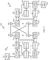
- FIG. 2 illustrates a block diagram of an aspect of a transmitter system 210 (also known as the access point) and a receiver system 250 (also known as the access terminal) in a multiple-input multiple-output (MIMO) system 200.
- a transmitter system 210 also known as the access point
- a receiver system 250 also known as the access terminal
- MIMO multiple-input multiple-output
- traffic data for a number of data streams is provided from a data source 212 to a transmit (TX) data processor 214.
- TX transmit
- each data stream may be transmitted over a respective transmit antenna.
- TX data processor 214 formats, codes, and interleaves the traffic data for each data stream based on a particular coding scheme selected for that data stream to provide coded data.
- the coded data for each data stream may be multiplexed with pilot data using OFDM techniques.
- the pilot data is typically a known data pattern that is processed in a known manner and may be used at the receiver system to estimate the channel response.
- the multiplexed pilot and coded data for each data stream is then modulated (i.e., symbol mapped) based on a particular modulation scheme (e.g., BPSK, QSPK, M-PSK, or M-QAM) selected for that data stream to provide modulation symbols.
- the data rate, coding, and modulation for each data stream may be determined by instructions stored in memory 232 and performed by processor 230.
- TX MIMO processor 220 may further process the modulation symbols (e.g., for OFDM).
- TX MIMO processor 220 then provides N T modulation symbol streams to N T transmitters (TMTR) 222a through 222t.
- TMTR TX MIMO processor 220 applies beamforming weights to the symbols of the data streams and to the antenna from which the symbol is being transmitted.
- Each transmitter 222 receives and processes a respective symbol stream to provide one or more analog signals, and further conditions (e.g., amplifies, filters, and upconverts) the analog signals to provide a modulated signal suitable for transmission over the MIMO channel.
- N T modulated signals from transmitters 222a through 222t are then transmitted from N T antennas 224a through 224t, respectively.
- the transmitted modulated signals may be received by N R antennas 252a through 252r and the received signal from each antenna 252 may be provided to a respective receiver (RCVR) 254a through 254r.
- Each receiver 254 may condition (e.g., filters, amplifies, and downconverts) a respective received signal, digitize the conditioned signal to provide samples, and further process the samples to provide a corresponding "received" symbol stream.
- An RX data processor 260 then receives and processes the N R received symbol streams from N R receivers 254 based on a particular receiver processing technique to provide N T "detected" symbol streams.
- the RX data processor 260 then demodulates, deinterleaves, and decodes each detected symbol stream to recover the traffic data for the data stream.
- the processing by RX data processor 260 may be complementary to that performed by TX MIMO processor 220 and TX data processor 214 at transmitter system 210.
- a processor 270 periodically determines which pre-coding matrix to use (discussed below). Processor 270 formulates a reverse link message comprising a matrix index portion and a rank value portion using instructions stored in memory 272.
- the reverse link message may comprise various types of information regarding the communication link and/or the received data stream.
- the reverse link message is then processed by a TX data processor 238, which also receives traffic data for a number of data streams from a data source 236, modulated by a modulator 280, conditioned by transmitters 254a through 254r, and transmitted back to transmitter system 210.
- the modulated signals from receiver system 250 are received by antennas 224, conditioned by receivers 222, demodulated by a demodulator 240, and processed by a RX data processor 242 to extract the reserve link message transmitted by the receiver system 250.
- Processor 230 determines which pre-coding matrix to use for determining the beamforming weights, and then processes the extracted message.
- FIG. 3 illustrates various components that may be utilized in a wireless device 302 that may be employed within the wireless communication system illustrated in FIG. 1 .
- the wireless device 302 is an example of a device that may be configured to implement the various methods described herein.
- the wireless device 302 may be a base station 100 or any of user terminals 116 and 122.
- the wireless device 302 may include a processor 304 which controls operation of the wireless device 302.
- the processor 304 may also be referred to as a central processing unit (CPU).
- Memory 306 which may include both read-only memory (ROM) and random access memory (RAM), provides instructions and data to the processor 304.
- a portion of the memory 306 may also include non-volatile random access memory (NVRAM).
- the processor 304 typically performs logical and arithmetic operations based on program instructions stored within the memory 306.
- the instructions in the memory 306 may be executable to implement the methods described herein.
- the wireless device 302 may also include a housing 308 that may include a transmitter 310 and a receiver 312 to allow transmission and reception of data between the wireless device 302 and a remote location.
- the transmitter 310 and receiver 312 may be combined into a transceiver 314.
- a single or a plurality of transmit antennas 316 may be attached to the housing 308 and electrically coupled to the transceiver 314.
- the wireless device 302 may also include (not shown) multiple transmitters, multiple receivers, and multiple transceivers.
- the wireless device 302 may also include a signal detector 318 that may be used in an effort to detect and quantify the level of signals received by the transceiver 314.
- the signal detector 318 may detect such signals as total energy, energy per subcarrier per symbol, power spectral density and other signals.
- the wireless device 302 may also include a digital signal processor (DSP) 320 for use in processing signals.
- DSP digital signal processor
- the various components of the wireless device 302 may be coupled together by a bus system 322, which may include a power bus, a control signal bus, and a status signal bus in addition to a data bus.
- a bus system 322 may include a power bus, a control signal bus, and a status signal bus in addition to a data bus.
- Logical control channels may comprise a Broadcast Control Channel (BCCH) which is a downlink (DL) channel for broadcasting system control information.
- a Paging Control Channel (PCCH) is a DL logical control channel that transfers paging information.
- a Multicast Control Channel (MCCH) is a point-to-multipoint DL logical control channel used for transmitting Multimedia Broadcast and Multicast Service (MBMS) scheduling and control information for one or several Multicast Traffic Channels (MTCHs).
- RRC Radio Resource Control
- the MCCH may be only used by user terminals that receive MBMS.
- a Dedicated Control Channel is a point-to-point bi-directional logical control channel that transmits dedicated control information and it is used by user terminals having an RRC connection.
- Logical traffic channels may comprise a Dedicated Traffic Channel (DTCH) which is a point-to-point bi-directional channel dedicated to one user terminal for transferring user information.
- logical traffic channels may comprise a Multicast Traffic Channel (MTCH), which is a point-to-multipoint DL channel for transmitting traffic data.
- DTCH Dedicated Traffic Channel
- MTCH Multicast Traffic Channel
- Transport channels may be classified into DL and UL channels.
- DL transport channels may comprise a Broadcast Channel (BCH), a Downlink Shared Data Channel (DL-SDCH) and a Paging Channel (PCH).
- the PCH may be utilized for supporting power saving at the user terminal (i.e., Discontinuous Reception (DRX) cycle may be indicated to the user terminal by the network), broadcasted over entire cell and mapped to physical layer (PHY) resources which can be used for other control/traffic channels.
- the UL transport channels may comprise a Random Access Channel (RACH), a Request Channel (REQCH), an Uplink Shared Data Channel (UL-SDCH) and a plurality of PHY channels.
- RACH Random Access Channel
- REQCH Request Channel
- UL-SDCH Uplink Shared Data Channel
- the PHY channels may comprise a set of DL channels and UL channels.
- the DL PHY channels may comprise: Common Pilot Channel (CPICH), Synchronization Channel (SCH), Common Control Channel (CCCH), Shared DL Control Channel (SDCCH), Multicast Control Channel (MCCH), Shared UL Assignment Channel (SUACH), Acknowledgement Channel (ACKCH), DL Physical Shared Data Channel (DL-PSDCH), UL Power Control Channel (UPCCH), Paging Indicator Channel (PICH), and Load Indicator Channel (LICH).
- CPICH Common Pilot Channel
- SCH Synchronization Channel
- CCCH Common Control Channel
- SDCCH Shared DL Control Channel
- MCCH Multicast Control Channel
- SUACH Shared UL Assignment Channel
- ACKCH Acknowledgement Channel
- DL-PSDCH DL Physical Shared Data Channel
- UPCH UL Power Control Channel
- PICH Paging Indicator Channel
- LICH Load Indicator Channel
- the UL PHY Channels may comprise: Physical Random Access Channel (PRACH), Channel Quality Indicator Channel (CQICH), Acknowledgement Channel (ACKCH), Antenna Subset Indicator Channel (ASICH), Shared Request Channel (SREQCH), UL Physical Shared Data Channel (UL-PSDCH), and Broadband Pilot Channel (BPICH).
- PRACH Physical Random Access Channel
- CQICH Channel Quality Indicator Channel
- ACKCH Acknowledgement Channel
- ASICH Antenna Subset Indicator Channel
- SREQCH Shared Request Channel
- UL-PSDCH UL Physical Shared Data Channel
- BPICH Broadband Pilot Channel
- LTE utilizes orthogonal frequency division multiplexing (OFDM) on the downlink and single-carrier frequency division multiplexing (SC-FDM) on the uplink.
- OFDM and SC-FDM partition the system bandwidth into multiple (K) orthogonal subcarriers, which are also commonly referred to as tones, bins, etc.
- K orthogonal subcarriers
- Each subcarrier may be modulated with data.
- modulation symbols are sent in the frequency domain with OFDM and in the time domain with SC-FDM.
- the spacing between adjacent subcarriers may be fixed, and the total number of subcarriers (K) may be dependent on the system bandwidth.
- the spacing of the subcarriers may be 15 kHz and the minimum resource allocation (called a 'resource block') may be 12 subcarriers (or 180 kHz). Consequently, the nominal FFT size may be equal to 128, 256, 512, 1024 or 2048 for system bandwidth of 1.25, 2.5, 5, 10 or 20 megahertz (MHz), respectively.
- the system bandwidth may also be partitioned into subbands. For example, a subband may cover 1.08 MHz (i.e., 6 resource blocks), and there may be 1, 2, 4, 8 or 16 subbands for system bandwidth of 1.25, 2.5, 5, 10 or 20 MHz, respectively.
- FIG. 4 shows a down link frame structure used in LTE.
- the transmission timeline for the downlink may be partitioned into units of radio frames.
- Each radio frame may have a predetermined duration (e.g., 10 milliseconds (ms)) and may be partitioned into 10 subframes with indices of 0 through 9.
- Each subframe may include two slots.
- Each radio frame may thus include 20 slots with indices of 0 through 19.
- Each slot may include L symbol periods, e.g., 7 symbol periods for a normal cyclic prefix (as shown in FIG. 4 ) or 14 symbol periods for an extended cyclic prefix.
- the 2L symbol periods in each subframe may be assigned indices of 0 through 2L-1.
- the available time frequency resources may be partitioned into resource blocks.
- Each resource block may cover N subcarriers (e.g., 12 subcarriers) in one slot.
- an eNodeB may send a primary synchronization signal (PSS) and a secondary synchronization signal (SSS) for each cell in the eNodeB.
- PSS primary synchronization signal
- SSS secondary synchronization signal
- the primary and secondary synchronization signals may be sent in symbol periods 6 and 5, respectively, in each of subframes 0 and 5 of each radio frame with the normal cyclic prefix, as shown in FIG. 4 .
- the synchronization signals may be used by UEs for cell detection and acquisition.
- the eNodeB may send a Physical Broadcast Channel (PBCH) in symbol periods 0 to 3 in slot 1 of subframe 0.
- PBCH Physical Broadcast Channel
- the eNodeB may send a Physical Control Format Indicator Channel (PCFICH) in only a portion of the first symbol period of each subframe, although depicted in the entire first symbol period in FIG. 4 .
- PHICH Physical HARQ Indicator Channel
- PDCCH Physical Downlink Control Channel
- the PHICH may carry information to support hybrid automatic retransmission (HARQ).
- the PDCCH may carry information on uplink and downlink resource allocation for UEs and power control information for uplink channels. Although not shown in the first symbol period in FIG. 4 , it is understood that the PDCCH and PHICH are also included in the first symbol period. Similarly, the PHICH and PDCCH are also both in the second and third symbol periods, although not .shown that way in FIG. 4 .
- the eNodeB may send a Physical Downlink Shared Channel (PDSCH) in the remaining symbol periods of each subframe.
- the PDSCH may carry data for UEs scheduled for data transmission on the downlink.
- the various signals and channels in LTE are described in 3GPP TS 36.211, entitled “Evolved Universal Terrestrial Radio Access (E-UTRA); Physical Channels and Modulation," which is publicly available.
- the eNodeB may send the PSS, SSS and PBCH in the center 1.08 MHz of the system bandwidth used by the eNodeB.
- the eNodeB may send the PCFICH and PHICH across the entire system bandwidth in each symbol period in which these channels are sent.
- the eNodeB may send the PDCCH to groups of UEs in certain portions of the system bandwidth.
- the eNodeB may send the PDSCH to specific UEs in specific portions of the system bandwidth.
- the eNodeB may send the PSS, SSS, PBCH, PCFICH and PHICH in a broadcast manner to all UEs, may send the PDCCH in a unicast manner to specific UEs, and may also send the PDSCH in a unicast manner to specific UEs.
- a number of resource elements may be available in each symbol period. Each resource element may cover one subcarrier in one symbol period and may be used to send one modulation symbol, which may be a real or complex value. Resource elements not used for a reference signal in each symbol period may be arranged into resource element groups (REGs). Each REG may include four resource elements in one symbol period.
- the PCFICH may occupy four REGs, which may be spaced approximately equally across frequency, in symbol period 0.
- the PHICH may occupy three REGs, which may be spread across frequency, in one or more configurable symbol periods. For example, the three REGs for the PHICH may all belong in symbol period 0 or may be spread in symbol periods 0, 1 and 2.
- the PDCCH may occupy 9, 18, 32 or 64 REGs, which may be selected from the available REGs, in the first M symbol periods. Only certain combinations of REGs may be allowed for the PDCCH.
- a UE may know the specific REGs used for the PHICH and the PCFICH.
- the UE may search different combinations of REGs for the PDCCH.
- the number of combinations to search is typically less than the number of allowed combinations for the PDCCH.
- An eNodeB may send the PDCCH to the UE in any of the combinations that the UE will search.
- a UE may be within the coverage of multiple eNodeBs.
- One of these eNodeBs may be selected to serve the UE.
- the serving eNodeB may be selected based on various criteria such as received power, path loss, signal-to-noise ratio (SNR), etc.
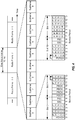
- LTE-Advanced UEs use spectrum up to 20 Mhz bandwidths allocated in a carrier aggregation of up to a total of 100 Mhz (5 component carriers) used for transmission in each direction.
- the uplink spectrum allocation may be smaller than the downlink allocation.
- the downlink may be assigned 100 Mhz.
- Non-continuous CA occurs when multiple available component carriers are separated along the frequency band ( FIG. 5B ).
- continuous CA occurs when multiple available component carriers are adjacent to each other ( FIG. 5A ).
- Both non-continuous and continuous CA aggregate multiple LTE/component carriers to serve a single unit of LTE Advanced UE.
- Non-continuous CA supports data transmissions over multiple separated carriers across a large frequency range, propagation path loss, Doppler shift and other radio channel characteristics may vary a lot at different frequency bands.
- methods may be used to adaptively adjust coding, modulation and transmission power for different component carriers.
- eNodeB enhanced NodeB
- the effective coverage or supportable modulation and coding of each component carrier may be different.
- FIG. 6 illustrates aggregating transmission blocks (TBs) from different component carriers at the medium access control (MAC) layer ( FIG. 6 ) for an IMT-Advanced system.
- MAC medium access control
- each component carrier has its own independent hybrid automatic repeat request (HARQ) entity in the MAC layer and its own transmission configuration parameters (e.g., transmitting power, modulation and coding schemes, and multiple antenna configuration) in the physical layer.
- HARQ hybrid automatic repeat request
- transmitting power e.g., transmitting power, modulation and coding schemes, and multiple antenna configuration
- one HARQ entity is provided for each component carrier.
- control channel signaling for multiple component carriers.
- the second method involves jointly coding the control channels of different component carriers and deploying the control channels in a dedicated component carrier.
- the control information for the multiple component carriers will be integrated as the signaling content in this dedicated control channel.
- control channels for different component carriers are jointly coded and then transmitted over the entire frequency band formed by a third CA method.
- This approach offers low signaling overhead and high decoding performance in control channels, at the expense of high power consumption at the UE side.
- this method is not compatible with LTE systems.
- the UE measures the performance of only one component carrier in each adjacent cell. This offers similar measurement delay, complexity, and energy consumption as that in LTE systems. An estimate of the performance of the other component carriers in the corresponding cell may be based on the measurement result of the one component carrier. Based on this estimate, the handover decision and transmission configuration may be determined.
- the UE operating in a multicarrier system is configured to aggregate certain functions of multiple carriers, such as control and feedback functions, on the same carrier, which may be referred to as a "primary carrier.”
- the remaining carriers that depend on the primary carrier for support are referred to as associated secondary carriers.
- the UE may aggregate control functions such as those provided by the optional dedicated channel (DCH), the nonscheduled grants, a physical uplink control channel (PUCCH), and/or a physical downlink control channel (PDCCH).
- DCH optional dedicated channel
- PUCCH physical uplink control channel
- PDCCH physical downlink control channel
- secondary carriers may be added or removed without affecting the basic operation of the UE, including physical channel establishment and RLF procedures which are layer 2 procedures, such as in the 3GPP technical specification 36.331 for the LTE RRC protocol.
- FIG. 7 illustrates a method 700 for controlling radio links in a multiple carrier wireless communication system by grouping physical channels according to one example.
- the method includes, at block 705, aggregating control functions from at least two carriers onto one carrier to form a primary carrier and one or more associated secondary carriers.
- communication links are established for the primary carrier and each secondary carrier. Then, communication is controlled based on the primary carrier in block 715.
- UE user equipment
- CC component carriers
- PCC primary component carrier
- SCCs secondary component carriers
- the PCC may be configured semi-statically by higher layers for each UE. More specifically, acknowledgement/ Negative acknowledgement (ACK/NAK) signals, channel quality indicator (CQI), and scheduling request (SR) information may be transmitted on the PCC over a physical uplink control channel (PUCCH).
- PUCCH physical uplink control channel
- the SCCs may not carry a PUCCH for a given UE.
- the LTE-A may further support parallel PUCCHs and physical uplink shared channels (PUSCHs).
- a UE may scale power of each channel to limit maximum power usage by the UE. Some of the channels may be given higher priority while scaling the power of different channels. For example, PUSCH with uplink control information (UCI) may be prioritized over PUSCH without UCI (e.g., power of PUSCH without UCI may be scaled down first (e.g., to zero)). Therefore, an example priority order may be as follows: PUCCH > PUSCH with UCI > PUSCH without UCI .
- UCI uplink control information
- the prioritization may also be performed regardless of whether the same or different component carriers are utilized.
- the UE may scale down the transmit power of each PUSCH when the total transmit power exceeds the maximum allowable transmit power per carrier (P CMAX ) of the UE.
- P CMAX maximum allowable transmit power per carrier
- the following power inequality may be used for scaling power of each PUSCH: ⁇ c w c ⁇ P PUSCH c i ⁇ P CMAX ⁇ P PUCCH i in which w c is a scaling factor for PUSCH on carrier c, P PUSCH c .represents the power used for PUSCH on carrier c, P PUCCH represents the power used for PUCCH transmissions, and i represents a subframe index.
- a sounding reference signal (SRS) for a UE may be transmitted either in the last symbol of an uplink (UL) subframe as in LTE TDD, or in one or both symbols of Uplink Pilot Time Slot (UpPTS).
- a sounding reference signal (SRS) is transmitted in the last symbol of a frame, if PUSCH is in the same component carrier as the SRS transmission, the last symbol may not be used for PUSCH.
- an SRS may be transmitted in the same component carrier as PUCCH, if the PUCCH uses shortened version of formats 1/1a/1b, which do not use the last symbol. However, if the PUCCH uses other formats such as formats 2/2a/2b or normal versions of the formats 1/1a/1b and the like, the SRS may be dropped.
- FIG. 8 illustrates exemplary operations 800 for transmit power allocation that may be performed by a UE, in accordance with aspects of the present disclosure.
- the operations begin, at 802, with the UE scaling transmission power of one or more uplink channel symbols to be transmitted in a subframe, utilizing a first set of one or more scaling coefficients.
- the UE scales transmission power of one or more sounding reference signal (SRS) symbols to be transmitted in the same subframe, utilizing a second set of one or more scaling coefficients.
- the first set of scaling coefficients is different from the second set of scaling coefficients.
- the UE may transmit the scaled one or more uplink channel symbols and the scaled one or more SRS symbols in the subframe.
- SRS sounding reference signal
- a first scenario involves scaling power of only SRS transmissions over all component carriers.
- a second scenario involves scaling power of SRS transmissions in conjunction with PUCCH across all component carriers.
- a third scenario involves scaling power of SRS transmissions in conjunction with PUSCH across all component carriers.
- a fourth scenario involves scaling power of SRS, PUCCH and PUSCH transmission across all component carriers.
- power of the SRS symbol may be scaled in a manner that is independent of power of other symbols in a subframe. Therefore, a power control equation may be retained for all physical channels as long as the maximum allowable power is not reached. For each component carrier, a power scaling coefficient similar to the one used for the SRS symbol in the same subframe may be applied to all symbols carrying PUSCH. In such a case, when maximum allowable power for a UE is reached, the SRS power transmission may be given priority over transmissions in PUCCH and/or PUSCH.
- transmission power of the SRS symbol may be similar to the transmission power of the other symbols in a subframe if a maximum transmission power is reached for the other symbols.
- the SRS may be transmitted with maximum power if other symbols in the same subframe are also transmitted with the maximum power.
- SRS channels may be transmitted over all the component carriers (e.g., no transmissions on PUCCH or PUSCH or no transmissions on the last symbol of the subframe)
- the UE may scale down the transmit power of each SRS transmissions on each of the component carriers such that the following power inequality is satisfied: ⁇ c V c * P SRSc i ⁇ P CMAX in which P SRS c represents power of SRS transmission on carrier c and V c represents scaling coefficient for power of SRS transmission on carrier c.
- This scaling coefficient may also be different from the scaling coefficient used for PUSCH transmissions.
- the UE may scale down the transmit power of each SRS such that the following power inequality is satisfied: ⁇ c V c * P SRSc i ⁇ P CMAX ⁇ P PUCCH i
- the third and fourth scenarios involve SRS transmissions in conjunction with PUSCH across all component carriers or SRS, PUCCH and PUSCH transmissions across all component carriers respectively.
- the UE may give priority to transmission in PUSCH and/or PUCCH and perform power scaling for SRS transmission using remaining power after enough power is allocated to PUSCH and/or PUCCH transmissions. Therefore, the following power inequality may be satisfied: ⁇ c V c * P SRSc i ⁇ P CMAX ⁇ P PUCCH i ⁇ ⁇ c W c * P PUSCHc i in which P PUSCHc (i) represents the component carrier with PUSCH transmission over the last symbol. It should be noted that in the above formula only PUSCH transmissions that are using the last symbol may be considered.
- the SRS transmission power allocation may be prioritized over PUSCH power allocation.
- PUSCH power may be scaled for the last symbol, e.g., for quadrature phase-shift keying (QPSK) modulation.
- QPSK quadrature phase-shift keying
- Another alternative for the third and fourth scenarios may be dropping SRS transmission. However, this may not be necessary if there is still room for SRS transmissions.
- the power scaling coefficients for SRS ( V c ) as described in the above equations may be determined similarly to determining power scaling factors for PUSCH ( w c ). For example, uniform scaling across all component carriers, non-uniform scaling across all component carriers (e.g., giving primary component carrier higher priority, etc.), and scaling in dB or linear domain may be considered. Priority rules may be similar to PUSCH and can be either specified by standard in use or may be left to UE implementation.
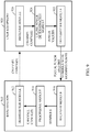
- FIG. 9 illustrates an example system 900 with a base station 910 and a user equipment 920 capable of performing the power scaling techniques in accordance with certain aspects of the present disclosure.
- the base station 910 may include a transmitter module 912 for transmitting control and channel configuration messages to the UE 920.
- the UE 920 may receives the channel configuration with a receiver module 926 and determine an amount of power that should be used for transmissions over a plurality of component carriers utilizing the uplink power determining module 924.
- the uplink power determining module 924 may utilize any technique or combination of techniques described above to determine scaling coefficients for scaling transmission power used for PUSCH and PUCCH transmissions over each component carrier.
- the uplink power determining module 924 may also determine transmit power for SRS transmissions over the last symbol of a subframe or the SRS symbols in UpPTS in TDD by determining scaling coefficients for the SRS transmissions over each component carrier.
- the UE may give priority to determining transmit power for either SRS symbols or PUCCH/PUSCH symbols.
- the transmitter module 922 transmits SRS symbols and PUSCH/PUCCH symbols utilizing the determined/scaled power values.
- the base station 910 receives the symbols with a receiver module 916 and processes the received symbols utilizing the processing module 914.
- the processing module 914 may also determine channel configuration signals for uplink transmissions from the UE.
- the various operations of methods described above may be performed by any suitable means capable of performing the corresponding functions.
- the means may include various hardware and/or software component(s) and/or module(s), including, but not limited to a circuit, an application specific integrate circuit (ASIC), or processor.
- ASIC application specific integrate circuit
- the various illustrative logical blocks, modules and circuits described in connection with the present disclosure may be implemented or performed with a general purpose processor, a digital signal processor (DSP), an application specific integrated circuit (ASIC), a field programmable gate array signal (FPGA) or other programmable logic device (PLD), discrete gate or transistor logic, discrete hardware components or any combination thereof designed to perform the functions described herein.
- DSP digital signal processor
- ASIC application specific integrated circuit
- FPGA field programmable gate array signal
- PLD programmable logic device
- a general-purpose processor may be a microprocessor, but in the alternative, the processor may be any commercially available processor, controller, microcontroller or state machine.
- a processor may also be implemented as a combination of computing devices, e.g., a combination of a DSP and a microprocessor, a plurality of microprocessors, one or more microprocessors in conjunction with a DSP core, or any other such configuration.
- a software module may reside in any form of storage medium that is known in the art. Some examples of storage media that may be used include random access memory (RAM), read only memory (ROM), flash memory, EPROM memory, EEPROM memory, registers, a hard disk, a removable disk, a CD-ROM and so forth.
- RAM random access memory
- ROM read only memory
- flash memory EPROM memory
- EEPROM memory EEPROM memory
- registers a hard disk, a removable disk, a CD-ROM and so forth.
- a software module may comprise a single instruction, or many instructions, and may be distributed over several different code segments, among different programs, and across multiple storage media.
- a storage medium may be coupled to a processor such that the processor can read information from, and write information to, the storage medium. In the alternative, the storage medium may be integral to the processor.
- the methods disclosed herein comprise one or more steps or actions for achieving the described method.
- the method steps and/or actions may be interchanged with one another without departing from the scope of the claims.
- the order and/or use of specific steps and/or actions may be modified without departing from the scope of the claims.
- the functions described may be implemented in hardware, software, firmware, or any combination thereof. If implemented in software, the functions may be stored on or transmitted over as one or more instructions or code on a computer-readable medium.
- Computer-readable media includes both computer storage media and communication media including any medium that facilitates transfer of a computer program from one place to another.
- a storage media may be any available media that can be accessed by a computer.
- such computer-readable media can comprise RAM, ROM, EEPROM, CD-ROM or other optical disk storage, magnetic disk storage or other magnetic storage devices, or any other medium that can be used to carry or store desired program code in the form of instructions or data structures and that can be accessed by a computer.
- any connection is properly termed a computer-readable medium.
- the software is transmitted from a website, server, or other remote source using a coaxial cable, fiber optic cable, twisted pair, digital subscriber line (DSL), or wireless technologies such as infrared, radio, and microwave
- the coaxial cable, fiber optic cable, twisted pair, DSL, or wireless technologies such as infrared, radio, and microwave are included in the definition of medium.
- Disk and disc includes compact disc (CD), laser disc, optical disc, digital versatile disc (DVD), floppy disk and blu-ray disc where disks usually reproduce data magnetically, while discs reproduce data optically with lasers. Combinations of the above should also be included within the scope of computer-readable media.
- certain aspects may comprise a computer program product for performing the operations presented herein.
- a computer program product may comprise a computer readable medium having instructions stored (and/or encoded) thereon, the instructions being executable by one or more processors to perform the operations described herein.
- the computer program product may include packaging material.
- Software or instructions may also be transmitted over a transmission medium.
- a transmission medium For example, if the software is transmitted from a website, server, or other remote source using a coaxial cable, fiber optic cable, twisted pair, digital subscriber line (DSL), or wireless technologies such as infrared, radio, and microwave, then the coaxial cable, fiber optic cable, twisted pair, DSL, or wireless technologies such as infrared, radio, and microwave are included in the definition of transmission medium.
- DSL digital subscriber line
- modules and/or other appropriate means for performing the methods and techniques described herein can be downloaded and/or otherwise obtained by a user terminal and/or base station as applicable.
- a user terminal and/or base station can be coupled to a server to facilitate the transfer of means for performing the methods described herein.
- various methods described herein can be provided via storage means (e.g., RAM, ROM, a physical storage medium such as a compact disc (CD) or floppy disk, etc.), such that a user terminal and/or base station can obtain the various methods upon coupling or providing the storage means to the device.
- storage means e.g., RAM, ROM, a physical storage medium such as a compact disc (CD) or floppy disk, etc.
- CD compact disc
- floppy disk etc.
- any other suitable technique for providing the methods and techniques described herein to a device can be utilized.
Landscapes
- Engineering & Computer Science (AREA)
- Computer Networks & Wireless Communication (AREA)
- Signal Processing (AREA)
- Mobile Radio Communication Systems (AREA)
Claims (15)
- Ein Verfahren (800) für Sounding Reference Signal, SRS, Leistungssteuerung für mehrfach Träger Szenarios, wobei das Verfahren folgende Schritte aufweist:Skalieren (802) einer Sendeleistung von einem oder mehreren Uplink Kanalsymbolen, die in einem Unterrahmen bzw. Subframe gesendet werden sollen, unter der Verwendung eines ersten Satzes von einem oder mehreren Skalierungskoeffizienten;Skalieren (804) einer Sendeleistung von einem oder mehreren Sounding Reference Signal, SRS, Symbolen, die in demselben Subframe gesendet werden sollen, unter der Verwendung eines zweiten Satzes von einem oder mehreren Skalierungskoeffizienten, wobei der erste Satz von Skalierungskoeffizienten unterschiedlich ist zu dem zweiten Satz von Skalierungskoeffizienten, wobei das Skalieren (804) der Sendeleistung von dem einen oder den mehreren SRS Symbolen folgende Schritte aufweist:Bestimmen einer Gesamtsendeleistung, die dem Senden des einen oder der mehreren SRS Symbole zugewiesen ist; undwenn die Gesamtsendeleistung eine maximale Sendeleistung pro Träger überschreitet, Bestimmen des zweiten Satzes von Skalierungskoeffizienten derart, dass ein einheitliches Skalieren über eine Vielzahl von Komponententrägern ausgeführt wird; undSenden (806) von wenigstens einem des skalierten einen oder der mehreren Uplinkkanal Symbole oder des skalierten einen oder der mehreren SRS Symbole, unter der Verwendung der skalierten Sendeleistungswerte.
- Das Verfahren (800) nach Anspruch 1, wobei das Senden das Senden auf einer Vielzahl von Komponententrägern aufweist.
- Das Verfahren (800) nach Anspruch 1, wobei der zweite Satz von Skalierungskoeffizienten gleich ist über eine Vielzahl von Komponententräger.
- Das Verfahren (800) nach Anspruch 1, wobei das Skalieren der Sendeleistung der Uplinkkanal Symbole, die in dem Subframe gesendet werden sollen, das Verwenden der gleichen Skalierungskoeffizienten für alle Uplink geteilten Kanalsymbole, die auf einem gemeinsamen Komponententräger gesendet werden.
- Das Verfahren (800) nach Anspruch 1, wobei das Verfahren ferner folgende Schritte aufweist:Bestimmen ob eine Sendeleistungsschwelle erreicht wurde; undwenn ja, Priorisieren von Sendungen von den Uplinkkanal Symbolen und den SRS Symbolen.
- Das Verfahren (800) nach Anspruch 5, wobei das Priorisieren folgende Schritte aufweist:Bestimmen des ersten Satzes von Leistungsskalierungskoeffizienten für das Senden der Uplinkkanal Symbole; undZuweisen der verbleibenden Sendeleistung, wenn der zweite Satz von Leistungsskalierungskoeffizienten zum Senden der SRS Symbole bestimmt wird, wobei die verbleibende Sendeleistung eine maximale Sendeleistung minus einer Leistung zum Senden der Uplinkkanal Symbole aufweist.
- Das Verfahren (500) nach Anspruch 5, wobei das Priorisieren Folgendes aufweist:Bestimmen des ersten Satzes von Leistungsskalierungskoeffizienten für die Sendung der Uplinkkanalsymbole;Zuweisen verbleibender Sendeleistung beim Bestimmen des zweiten Satzes von Leistungsskalierungskoeffizienten für die Sendung von SRS-Symbolen, wobei die verbleibende Sendeleistung eine maximale Sendeliestung minus eine Leistung, die für die Sendung der Uplinkkanalsymbole zugewiesen ist, aufweist.
- Das Verfahren (800) nach Anspruch 1, wobei das Verfahren ferner folgende Schritte aufweist:Bestimmen ob die Sendeleistung des Uplinkkanal Symbols gleich oder größer als eine Schwelle ist, undwenn ja, Senden des SRS Symbols unter der Verwendung einer maximalen Leistung.
- Das Verfahren (800) nach Anspruch 1, wobei das Skalieren der Sendeleistung von dem einen oder den mehreren SRS Symbolen ferner folgende Schritte aufweist:Bestimmen einer Gesamtsendeleistung, die Sendungen von dem einen oder den mehreren SRS Symbolen zugewiesen ist; undwenn die Gesamtsendeleistung eine maximale Sendeleistung des Benutzerendgerätes überschreitet, Bestimmen des zweiten Satzes von Skalierungskoeffizienten derart, dass die Summe des einen oder der mehreren skalierten Sendeleistungswerte zum Senden der SRS Symbole auf einer Vielzahl von Komponententrägern kleiner oder gleich einem vorbestimmten Wert ist.
- Das Verfahren (800) nach Anspruch 9, wobei der vorbestimmte Wert der maximalen Sendeleistung des Benutzerendgerätes entspricht.
- Das Verfahren (800) nach Anspruch 9, wobei der vorbestimmte Wert der maximalen Sendeleistung des Benutzerendgerätes minus einer Gesamtsendeleistung ist, die dem Senden auf einem Uplink Steuerkanal zugewiesen ist.
- Das Verfahren (800) nach Anspruch 9, wobei der vorbestimmte Wert der maximalen Sendeleistung des Benutzerendgerätes minus einer Gesamtsendeleistung ist, die dem Senden auf einem Uplink Steuerkanal zugewiesen ist minus der Gesamtsendeleistung, die Sendungen in Uplink geteilten Kanälen für die Vielzahl von Komponententrägern zugewiesen ist.
- Eine Vorrichtung (920) für Sounding Reference Signal, SRS, Leistungssteuerung für mehrfach Träger Szenarios, wobei die Vorrichtung Folgendes aufweist:Mittel (924) zum Skalieren einer Sendeleistung von einem oder mehreren Uplink Kanalsymbolen, die in einem Unterrahmen bzw. Subframe gesendet werden sollen, unter der Verwendung eines ersten Satzes von einem oder mehreren Skalierungskoeffizienten;Mittel (924) zum Skalieren einer Sendeleistung von einem oder mehreren Sounding Reference Signal, SRS, Symbolen, die in demselben Subframe gesendet werden sollen, unter der Verwendung eines zweiten Satzes von einem oder mehreren Skalierungskoeffizienten, wobei der erste Satz von Skalierungskoeffizienten unterschiedlich ist zu dem zweiten Satz von Skalierungskoeffizienten, wobei das Skalieren (804) der Sendeleistung von dem einen oder den mehreren SRS Symbolen Folgendes aufweist:Bestimmen einer Gesamtsendeleistung, die dem Senden des einen oder der mehreren SRS Symbole zugewiesen ist; undwenn die Gesamtsendeleistung eine maximale Sendeleistung eines Benutzerendgerätes überschreitet, Bestimmen des zweiten Satzes von Skalierungskoeffizienten derart, dass ein einheitliches Skalieren über eine Vielzahl von Komponententrägern ausgeführt wird; undMittel (922) zum Senden von wenigstens einem des skalierten einen oder der mehreren Uplinkkanal Symbole oder des skalierten einen oder der mehreren SRS Symbole, unter der Verwendung der skalierten Sendeleistungswerte.
- Die Vorrichtung (920) nach Anspruch 13, wobei die Mittel (924) zum Skalieren der Sendeleistung von dem einen oder den mehreren SRS Symbolen ferner Folgendes aufweist:Mittel (924) zum Bestimmen einer Gesamtsendeleistung, die dem Senden von dem einen oder den mehreren SRS Symbolen zugewiesen ist; undwenn die Gesamtsendeleistung eine maximale Sendeleistung des Benutzerendgerätes überschreitet, Mittel zum Bestimmen des zweiten Satzes von Skalierungskoeffizienten derart, dass die Summe des einen oder der mehreren skalierten Sendeleistungswerte zum Senden der SRS Symbole auf einer Vielzahl von Komponententrägern kleiner oder gleich einem vorbestimmten Wert ist.
- Ein Computerprogramm Produkt für Sounding Reference Signal, SRS, Leistungssteuerung für mehrfach Träger Szenarios, wobei das Produkt ein computerlesbares Medium aufweist, auf dem Anweisungen gespeichert sind, die, wenn sie von einem oder mehreren Prozessoren ausgeführt werden, den einen oder die mehreren Prozessoren dazu veranlassen die Verfahrensschritte nach einem der Ansprüche 1 bis 12 auszuführen.
Applications Claiming Priority (3)
| Application Number | Priority Date | Filing Date | Title |
|---|---|---|---|
| US33176910P | 2010-05-05 | 2010-05-05 | |
| US13/100,252 US9363769B2 (en) | 2010-05-05 | 2011-05-03 | Methods and systems for SRS power scaling in carrier aggregation |
| PCT/US2011/035400 WO2011140373A1 (en) | 2010-05-05 | 2011-05-05 | Methods and systems for srs power scaling in carrier aggregation |
Publications (2)
| Publication Number | Publication Date |
|---|---|
| EP2567577A1 EP2567577A1 (de) | 2013-03-13 |
| EP2567577B1 true EP2567577B1 (de) | 2017-09-20 |
Family
ID=44902256
Family Applications (1)
| Application Number | Title | Priority Date | Filing Date |
|---|---|---|---|
| EP11721872.7A Active EP2567577B1 (de) | 2010-05-05 | 2011-05-05 | Verfahren und system für srs-leistungsskalierung in der trägeraggregation |
Country Status (9)
| Country | Link |
|---|---|
| US (1) | US9363769B2 (de) |
| EP (1) | EP2567577B1 (de) |
| JP (2) | JP5792289B2 (de) |
| KR (2) | KR101620523B1 (de) |
| CN (1) | CN102870476B (de) |
| ES (1) | ES2647065T3 (de) |
| HU (1) | HUE033686T2 (de) |
| TW (1) | TWI488520B (de) |
| WO (1) | WO2011140373A1 (de) |
Families Citing this family (59)
| Publication number | Priority date | Publication date | Assignee | Title |
|---|---|---|---|---|
| ES2588978T3 (es) | 2010-04-02 | 2016-11-08 | Interdigital Patent Holdings, Inc. | Configuración y transmisión de señales de sondeo de referencia de enlace ascendente |
| US20110274063A1 (en) * | 2010-05-10 | 2011-11-10 | Ming-Che Li | Method and apparatus for handling dynamic aperiodic srs (sounding reference signal) in a wireless communication network |
| US9131457B2 (en) * | 2010-08-12 | 2015-09-08 | Samsung Electronics Co., Ltd. | Apparatus and method for transmission of uplink sounding reference signals in a wireless network |
| US9258092B2 (en) * | 2010-09-17 | 2016-02-09 | Blackberry Limited | Sounding reference signal transmission in carrier aggregation |
| US9661588B2 (en) | 2010-11-05 | 2017-05-23 | Sun Patent Trust | Wireless communication terminal device and power allocation method |
| US9118452B2 (en) | 2011-03-28 | 2015-08-25 | Lg Electronics Inc. | Method for transmitting an uplink signal, method for receiving an uplink signal, user equipment, and base station |
| US8395985B2 (en) | 2011-07-25 | 2013-03-12 | Ofinno Technologies, Llc | Time alignment in multicarrier OFDM network |
| KR101748107B1 (ko) * | 2011-07-29 | 2017-06-15 | 후지쯔 가부시끼가이샤 | 파워 제어 방법 및 단말 장치 |
| US9521632B2 (en) | 2011-08-15 | 2016-12-13 | Google Technology Holdings LLC | Power allocation for overlapping transmission when multiple timing advances are used |
| KR102014792B1 (ko) | 2011-09-21 | 2019-08-27 | 엘지전자 주식회사 | 상향링크 신호 전송 전력을 제어하는 단말 장치 및 그 방법 |
| CN102573030B (zh) * | 2011-12-08 | 2014-11-05 | 电信科学技术研究院 | 一种上行功率控制方法及装置 |
| US8964780B2 (en) | 2012-01-25 | 2015-02-24 | Ofinno Technologies, Llc | Sounding in multicarrier wireless communications |
| US8964683B2 (en) | 2012-04-20 | 2015-02-24 | Ofinno Technologies, Llc | Sounding signal in a multicarrier wireless device |
| EP3937551A3 (de) | 2012-01-25 | 2022-02-09 | Comcast Cable Communications, LLC | Direktzugriffskanal in einer drahtlosen mehrträgerkommunikation mit zeitvorlaufsgruppen |
| US9237537B2 (en) | 2012-01-25 | 2016-01-12 | Ofinno Technologies, Llc | Random access process in a multicarrier base station and wireless device |
| CA2862197A1 (en) * | 2012-01-29 | 2013-08-01 | Telefonaktiebolaget L M Ericsson (Publ) | User equipment, network node and method for applying power scaling to uplink transmissions |
| WO2013129809A1 (ko) * | 2012-02-27 | 2013-09-06 | 엘지전자 주식회사 | 무선 통신 시스템에서 상향링크 송신 전력을 제어하는 방법 및 이를 위한 장치 |
| US9503985B2 (en) | 2012-03-29 | 2016-11-22 | Sckipio Technologies S.I Ltd | Transmission scheme for communication systems |
| US11943813B2 (en) | 2012-04-01 | 2024-03-26 | Comcast Cable Communications, Llc | Cell grouping for wireless communications |
| US20130259008A1 (en) | 2012-04-01 | 2013-10-03 | Esmael Hejazi Dinan | Random Access Response Process in a Wireless Communications |
| WO2013151651A1 (en) | 2012-04-01 | 2013-10-10 | Dinan Esmael Hejazi | Cell group configuration in a wireless device and base station with timing advance groups |
| US11582704B2 (en) | 2012-04-16 | 2023-02-14 | Comcast Cable Communications, Llc | Signal transmission power adjustment in a wireless device |
| US11825419B2 (en) | 2012-04-16 | 2023-11-21 | Comcast Cable Communications, Llc | Cell timing in a wireless device and base station |
| US9210664B2 (en) | 2012-04-17 | 2015-12-08 | Ofinno Technologies. LLC | Preamble transmission in a wireless device |
| US11252679B2 (en) | 2012-04-16 | 2022-02-15 | Comcast Cable Communications, Llc | Signal transmission power adjustment in a wireless device |
| EP3337079B1 (de) | 2012-04-16 | 2024-06-05 | Comcast Cable Communications, LLC | Zellgruppenkonfiguration für uplink-übertragung in einer drahtlosen mehrträgervorrichtung und basisstation mit zeitvorlaufsgruppen |
| US8964593B2 (en) * | 2012-04-16 | 2015-02-24 | Ofinno Technologies, Llc | Wireless device transmission power |
| US9179425B2 (en) | 2012-04-17 | 2015-11-03 | Ofinno Technologies, Llc | Transmit power control in multicarrier communications |
| US10057893B2 (en) * | 2012-05-10 | 2018-08-21 | Qualcomm Incorporated | Interaction of sounding reference signals with uplink channels for coordinated multi-point operations |
| US9647808B2 (en) * | 2012-06-11 | 2017-05-09 | Nokia Solution And Networks Oy | Bandwidth in wireless communications |
| US9179457B2 (en) | 2012-06-20 | 2015-11-03 | Ofinno Technologies, Llc | Carrier configuration in wireless networks |
| US9210619B2 (en) | 2012-06-20 | 2015-12-08 | Ofinno Technologies, Llc | Signalling mechanisms for wireless device handover |
| US9113387B2 (en) | 2012-06-20 | 2015-08-18 | Ofinno Technologies, Llc | Handover signalling in wireless networks |
| US9084228B2 (en) | 2012-06-20 | 2015-07-14 | Ofinno Technologies, Llc | Automobile communication device |
| US8971298B2 (en) | 2012-06-18 | 2015-03-03 | Ofinno Technologies, Llc | Wireless device connection to an application server |
| US9107206B2 (en) | 2012-06-18 | 2015-08-11 | Ofinne Technologies, LLC | Carrier grouping in multicarrier wireless networks |
| US11882560B2 (en) | 2012-06-18 | 2024-01-23 | Comcast Cable Communications, Llc | Carrier grouping in multicarrier wireless networks |
| US11622372B2 (en) | 2012-06-18 | 2023-04-04 | Comcast Cable Communications, Llc | Communication device |
| WO2014054043A1 (en) * | 2012-10-03 | 2014-04-10 | Sckipio Technologies S.I Ltd | Hybrid precoder |
| US20140211647A1 (en) * | 2013-01-28 | 2014-07-31 | Innovative Sonic Corporation | Method and apparatus of small cell enhancement in a wireless communication system |
| CN103200605B (zh) * | 2013-03-01 | 2016-08-10 | 西安电子科技大学 | 一种基于载波聚合系统的上行功率消减方法及装置 |
| KR102222880B1 (ko) * | 2013-10-11 | 2021-03-04 | 삼성전자 주식회사 | 셀룰러 이동 통신 시스템에서 srs 전송 방법 및 장치 |
| US10263745B2 (en) | 2015-03-14 | 2019-04-16 | Qualcomm Incorporated | Reciprocal channel sounding reference signal allocation and configuration |
| US10404423B2 (en) * | 2016-03-18 | 2019-09-03 | Qualcomm Incorporated | Techniques for communicating in an expanded uplink pilot time slot |
| WO2017222315A1 (ko) * | 2016-06-22 | 2017-12-28 | 엘지전자 주식회사 | 상향링크 채널의 전송 파워를 결정하는 방법 및 단말 |
| US9769773B1 (en) * | 2017-01-09 | 2017-09-19 | Sprint Spectrum L.P. | Controlling per-carrier maximum transmit power of a device served on a plurality of carriers |
| WO2018230901A1 (ko) * | 2017-06-15 | 2018-12-20 | 삼성전자 주식회사 | 빔포밍 시스템에서 단말의 송신 전력 제어 방법 및 장치 |
| CN115038154B (zh) * | 2017-06-16 | 2025-08-15 | 中兴通讯股份有限公司 | 发送功率的确定方法及装置、终端 |
| US11076409B2 (en) * | 2018-07-30 | 2021-07-27 | Qualcomm Incorporated | Power allocation for subband precoding |
| CN110536395B (zh) | 2018-08-03 | 2022-09-13 | 中兴通讯股份有限公司 | 功率确定、信号发送方法、装置、网络设备和存储介质 |
| CN111050390B (zh) * | 2018-10-12 | 2021-11-02 | 大唐移动通信设备有限公司 | 一种上行功率控制方法、终端设备及网络设备 |
| US11778569B2 (en) * | 2019-01-21 | 2023-10-03 | Qualcomm Incorporated | Physical uplink shared channel (PUSCH) power scaling factor reporting |
| US11064442B1 (en) * | 2020-01-21 | 2021-07-13 | Sprint Communications Company L.P. | Uplink channel power management in dual connectivity devices |
| US11811529B2 (en) | 2020-06-24 | 2023-11-07 | Qualcomm Incorporated | Rate-matching, puncturing, and power scaling uplink communications in full duplex mode |
| CN114080025B (zh) * | 2020-07-29 | 2025-03-25 | 维沃移动通信有限公司 | 功率分配方法、装置及设备 |
| KR20220042929A (ko) * | 2020-09-28 | 2022-04-05 | 삼성전자주식회사 | 무선 통신 시스템에서 단말의 송신 전력 제어 방법 및 장치 |
| WO2023146225A1 (ko) * | 2022-01-28 | 2023-08-03 | 엘지전자 주식회사 | 무선 통신 시스템에서 상향링크 송수신을 수행하는 방법 및 장치 |
| CN120693925A (zh) * | 2022-12-29 | 2025-09-23 | 瑞典爱立信有限公司 | 探测参考信号的自适应功率提升 |
| US20250126578A1 (en) * | 2023-10-17 | 2025-04-17 | Samsung Electronics Company, Ltd. | Systems and Methods for Multiple Access Based on Controlling Transmit Power of Multiple Transmit Antennas |
Citations (1)
| Publication number | Priority date | Publication date | Assignee | Title |
|---|---|---|---|---|
| WO2010107880A2 (en) * | 2009-03-17 | 2010-09-23 | Interdigital Patent Holdings, Inc. | Method and apparatus for power control of sounding reference signal (srs) transmission |
Family Cites Families (12)
| Publication number | Priority date | Publication date | Assignee | Title |
|---|---|---|---|---|
| CA2330267C (en) * | 2000-02-28 | 2006-03-14 | Lucent Technologies Inc. | Reverse link outer loop power control with adaptive compensation |
| CN100583718C (zh) | 2004-06-09 | 2010-01-20 | 三星电子株式会社 | 移动电信系统中用于数据传输的方法和设备 |
| CN101180812B (zh) | 2005-03-30 | 2011-11-16 | 西门子公司 | 用于缩放e-dch信道的方法 |
| CN101874370B (zh) * | 2007-11-26 | 2014-04-16 | 夏普株式会社 | 无线通信系统、无线发送装置、无线通信方法以及程序 |
| US8472967B2 (en) | 2008-02-01 | 2013-06-25 | Qualcomm Incorporated | Allocating transmit power among two or more carriers assigned to a wireless communication device |
| KR101674940B1 (ko) * | 2009-01-29 | 2016-11-10 | 엘지전자 주식회사 | 전송 전력을 제어하는 방법 및 이를 위한 장치 |
| KR101697596B1 (ko) * | 2009-01-29 | 2017-01-18 | 엘지전자 주식회사 | 전송 전력을 제어하는 방법 및 이를 위한 장치 |
| WO2010098593A2 (en) | 2009-02-25 | 2010-09-02 | Lg Electronics Inc. | Method and device for controling transmission power in uplink transmission |
| CN201780605U (zh) * | 2009-04-22 | 2011-03-30 | 万信电子科技有限公司 | 服装试穿系统 |
| ES2588978T3 (es) * | 2010-04-02 | 2016-11-08 | Interdigital Patent Holdings, Inc. | Configuración y transmisión de señales de sondeo de referencia de enlace ascendente |
| US8965442B2 (en) * | 2010-05-07 | 2015-02-24 | Qualcomm Incorporated | Uplink power control in aggregated carrier communication systems |
| US9131457B2 (en) * | 2010-08-12 | 2015-09-08 | Samsung Electronics Co., Ltd. | Apparatus and method for transmission of uplink sounding reference signals in a wireless network |
-
2011
- 2011-05-03 US US13/100,252 patent/US9363769B2/en active Active
- 2011-05-05 WO PCT/US2011/035400 patent/WO2011140373A1/en not_active Ceased
- 2011-05-05 CN CN201180021866.5A patent/CN102870476B/zh active Active
- 2011-05-05 ES ES11721872.7T patent/ES2647065T3/es active Active
- 2011-05-05 KR KR1020127031789A patent/KR101620523B1/ko active Active
- 2011-05-05 HU HUE11721872A patent/HUE033686T2/en unknown
- 2011-05-05 EP EP11721872.7A patent/EP2567577B1/de active Active
- 2011-05-05 JP JP2013509274A patent/JP5792289B2/ja active Active
- 2011-05-05 TW TW100115833A patent/TWI488520B/zh active
- 2011-05-05 KR KR1020157007167A patent/KR20150038718A/ko not_active Withdrawn
-
2015
- 2015-04-08 JP JP2015079221A patent/JP2015164325A/ja active Pending
Patent Citations (1)
| Publication number | Priority date | Publication date | Assignee | Title |
|---|---|---|---|---|
| WO2010107880A2 (en) * | 2009-03-17 | 2010-09-23 | Interdigital Patent Holdings, Inc. | Method and apparatus for power control of sounding reference signal (srs) transmission |
Also Published As
| Publication number | Publication date |
|---|---|
| HUE033686T2 (en) | 2017-12-28 |
| JP5792289B2 (ja) | 2015-10-07 |
| WO2011140373A1 (en) | 2011-11-10 |
| CN102870476A (zh) | 2013-01-09 |
| JP2013529022A (ja) | 2013-07-11 |
| TW201212683A (en) | 2012-03-16 |
| KR20130043111A (ko) | 2013-04-29 |
| EP2567577A1 (de) | 2013-03-13 |
| KR20150038718A (ko) | 2015-04-08 |
| US9363769B2 (en) | 2016-06-07 |
| JP2015164325A (ja) | 2015-09-10 |
| ES2647065T3 (es) | 2017-12-19 |
| CN102870476B (zh) | 2016-08-03 |
| KR101620523B1 (ko) | 2016-05-12 |
| TWI488520B (zh) | 2015-06-11 |
| US20110275335A1 (en) | 2011-11-10 |
Similar Documents
| Publication | Publication Date | Title |
|---|---|---|
| EP2567577B1 (de) | Verfahren und system für srs-leistungsskalierung in der trägeraggregation | |
| US11722264B2 (en) | Acknowledgement / negative acknowledgement feedback for TDD | |
| US8982743B2 (en) | DAI designs for FDD carrier aggregation | |
| CN103503507B (zh) | 管理用于信道状态信息反馈的无效参考子帧的系统和方法 | |
| KR102877881B1 (ko) | 향상된 머신 유형 통신을 위한 재튜닝 | |
| KR101512725B1 (ko) | 다운링크 채널 자원 할당을 위한 방법들 및 장치들 | |
| US9107191B2 (en) | System and method for managing simultaneous uplink signal transmissions in carrier aggregation systems | |
| US8792370B2 (en) | Carrier preconfiguration for PDCCH monitoring in multi-carrier systems | |
| CN107735979A (zh) | 用于上行链路传输的机器类型通信(mtc)配置、干扰管理、以及重新调谐时间 | |
| CN111835493A (zh) | 用于低成本用户设备的窄带划分和高效资源分配 |
Legal Events
| Date | Code | Title | Description |
|---|---|---|---|
| PUAI | Public reference made under article 153(3) epc to a published international application that has entered the european phase |
Free format text: ORIGINAL CODE: 0009012 |
|
| 17P | Request for examination filed |
Effective date: 20121204 |
|
| AK | Designated contracting states |
Kind code of ref document: A1 Designated state(s): AL AT BE BG CH CY CZ DE DK EE ES FI FR GB GR HR HU IE IS IT LI LT LU LV MC MK MT NL NO PL PT RO RS SE SI SK SM TR |
|
| DAX | Request for extension of the european patent (deleted) | ||
| 17Q | First examination report despatched |
Effective date: 20131004 |
|
| REG | Reference to a national code |
Ref country code: DE Ref legal event code: R079 Ref document number: 602011041708 Country of ref document: DE Free format text: PREVIOUS MAIN CLASS: H04W0052280000 Ipc: H04W0052140000 |
|
| RIC1 | Information provided on ipc code assigned before grant |
Ipc: H04W 52/14 20090101AFI20160310BHEP Ipc: H04W 52/42 20090101ALI20160310BHEP Ipc: H04W 52/36 20090101ALI20160310BHEP Ipc: H04W 52/34 20090101ALI20160310BHEP Ipc: H04W 52/28 20090101ALI20160310BHEP |
|
| GRAP | Despatch of communication of intention to grant a patent |
Free format text: ORIGINAL CODE: EPIDOSNIGR1 |
|
| INTG | Intention to grant announced |
Effective date: 20160415 |
|
| GRAJ | Information related to disapproval of communication of intention to grant by the applicant or resumption of examination proceedings by the epo deleted |
Free format text: ORIGINAL CODE: EPIDOSDIGR1 |
|
| INTC | Intention to grant announced (deleted) | ||
| GRAS | Grant fee paid |
Free format text: ORIGINAL CODE: EPIDOSNIGR3 |
|
| GRAP | Despatch of communication of intention to grant a patent |
Free format text: ORIGINAL CODE: EPIDOSNIGR1 |
|
| INTG | Intention to grant announced |
Effective date: 20170406 |
|
| GRAA | (expected) grant |
Free format text: ORIGINAL CODE: 0009210 |
|
| AK | Designated contracting states |
Kind code of ref document: B1 Designated state(s): AL AT BE BG CH CY CZ DE DK EE ES FI FR GB GR HR HU IE IS IT LI LT LU LV MC MK MT NL NO PL PT RO RS SE SI SK SM TR |
|
| REG | Reference to a national code |
Ref country code: GB Ref legal event code: FG4D |
|
| REG | Reference to a national code |
Ref country code: CH Ref legal event code: EP |
|
| REG | Reference to a national code |
Ref country code: AT Ref legal event code: REF Ref document number: 931046 Country of ref document: AT Kind code of ref document: T Effective date: 20171015 |
|
| REG | Reference to a national code |
Ref country code: IE Ref legal event code: FG4D |
|
| REG | Reference to a national code |
Ref country code: DE Ref legal event code: R096 Ref document number: 602011041708 Country of ref document: DE |
|
| REG | Reference to a national code |
Ref country code: ES Ref legal event code: FG2A Ref document number: 2647065 Country of ref document: ES Kind code of ref document: T3 Effective date: 20171219 |
|
| REG | Reference to a national code |
Ref country code: HU Ref legal event code: AG4A Ref document number: E033686 Country of ref document: HU |
|
| REG | Reference to a national code |
Ref country code: NL Ref legal event code: FP |
|
| PG25 | Lapsed in a contracting state [announced via postgrant information from national office to epo] |
Ref country code: SE Free format text: LAPSE BECAUSE OF FAILURE TO SUBMIT A TRANSLATION OF THE DESCRIPTION OR TO PAY THE FEE WITHIN THE PRESCRIBED TIME-LIMIT Effective date: 20170920 Ref country code: NO Free format text: LAPSE BECAUSE OF FAILURE TO SUBMIT A TRANSLATION OF THE DESCRIPTION OR TO PAY THE FEE WITHIN THE PRESCRIBED TIME-LIMIT Effective date: 20171220 Ref country code: LT Free format text: LAPSE BECAUSE OF FAILURE TO SUBMIT A TRANSLATION OF THE DESCRIPTION OR TO PAY THE FEE WITHIN THE PRESCRIBED TIME-LIMIT Effective date: 20170920 Ref country code: HR Free format text: LAPSE BECAUSE OF FAILURE TO SUBMIT A TRANSLATION OF THE DESCRIPTION OR TO PAY THE FEE WITHIN THE PRESCRIBED TIME-LIMIT Effective date: 20170920 |
|
| REG | Reference to a national code |
Ref country code: LT Ref legal event code: MG4D |
|
| REG | Reference to a national code |
Ref country code: AT Ref legal event code: MK05 Ref document number: 931046 Country of ref document: AT Kind code of ref document: T Effective date: 20170920 |
|
| PG25 | Lapsed in a contracting state [announced via postgrant information from national office to epo] |
Ref country code: BG Free format text: LAPSE BECAUSE OF FAILURE TO SUBMIT A TRANSLATION OF THE DESCRIPTION OR TO PAY THE FEE WITHIN THE PRESCRIBED TIME-LIMIT Effective date: 20171220 Ref country code: GR Free format text: LAPSE BECAUSE OF FAILURE TO SUBMIT A TRANSLATION OF THE DESCRIPTION OR TO PAY THE FEE WITHIN THE PRESCRIBED TIME-LIMIT Effective date: 20171221 Ref country code: LV Free format text: LAPSE BECAUSE OF FAILURE TO SUBMIT A TRANSLATION OF THE DESCRIPTION OR TO PAY THE FEE WITHIN THE PRESCRIBED TIME-LIMIT Effective date: 20170920 Ref country code: RS Free format text: LAPSE BECAUSE OF FAILURE TO SUBMIT A TRANSLATION OF THE DESCRIPTION OR TO PAY THE FEE WITHIN THE PRESCRIBED TIME-LIMIT Effective date: 20170920 |
|
| REG | Reference to a national code |
Ref country code: FR Ref legal event code: PLFP Year of fee payment: 8 |
|
| PG25 | Lapsed in a contracting state [announced via postgrant information from national office to epo] |
Ref country code: RO Free format text: LAPSE BECAUSE OF FAILURE TO SUBMIT A TRANSLATION OF THE DESCRIPTION OR TO PAY THE FEE WITHIN THE PRESCRIBED TIME-LIMIT Effective date: 20170920 Ref country code: PL Free format text: LAPSE BECAUSE OF FAILURE TO SUBMIT A TRANSLATION OF THE DESCRIPTION OR TO PAY THE FEE WITHIN THE PRESCRIBED TIME-LIMIT Effective date: 20170920 Ref country code: CZ Free format text: LAPSE BECAUSE OF FAILURE TO SUBMIT A TRANSLATION OF THE DESCRIPTION OR TO PAY THE FEE WITHIN THE PRESCRIBED TIME-LIMIT Effective date: 20170920 |
|
| PG25 | Lapsed in a contracting state [announced via postgrant information from national office to epo] |
Ref country code: SK Free format text: LAPSE BECAUSE OF FAILURE TO SUBMIT A TRANSLATION OF THE DESCRIPTION OR TO PAY THE FEE WITHIN THE PRESCRIBED TIME-LIMIT Effective date: 20170920 Ref country code: AT Free format text: LAPSE BECAUSE OF FAILURE TO SUBMIT A TRANSLATION OF THE DESCRIPTION OR TO PAY THE FEE WITHIN THE PRESCRIBED TIME-LIMIT Effective date: 20170920 Ref country code: IS Free format text: LAPSE BECAUSE OF FAILURE TO SUBMIT A TRANSLATION OF THE DESCRIPTION OR TO PAY THE FEE WITHIN THE PRESCRIBED TIME-LIMIT Effective date: 20180120 Ref country code: EE Free format text: LAPSE BECAUSE OF FAILURE TO SUBMIT A TRANSLATION OF THE DESCRIPTION OR TO PAY THE FEE WITHIN THE PRESCRIBED TIME-LIMIT Effective date: 20170920 Ref country code: SM Free format text: LAPSE BECAUSE OF FAILURE TO SUBMIT A TRANSLATION OF THE DESCRIPTION OR TO PAY THE FEE WITHIN THE PRESCRIBED TIME-LIMIT Effective date: 20170920 |
|
| REG | Reference to a national code |
Ref country code: DE Ref legal event code: R097 Ref document number: 602011041708 Country of ref document: DE |
|
| PLBE | No opposition filed within time limit |
Free format text: ORIGINAL CODE: 0009261 |
|
| STAA | Information on the status of an ep patent application or granted ep patent |
Free format text: STATUS: NO OPPOSITION FILED WITHIN TIME LIMIT |
|
| PG25 | Lapsed in a contracting state [announced via postgrant information from national office to epo] |
Ref country code: DK Free format text: LAPSE BECAUSE OF FAILURE TO SUBMIT A TRANSLATION OF THE DESCRIPTION OR TO PAY THE FEE WITHIN THE PRESCRIBED TIME-LIMIT Effective date: 20170920 |
|
| 26N | No opposition filed |
Effective date: 20180621 |
|
| PG25 | Lapsed in a contracting state [announced via postgrant information from national office to epo] |
Ref country code: SI Free format text: LAPSE BECAUSE OF FAILURE TO SUBMIT A TRANSLATION OF THE DESCRIPTION OR TO PAY THE FEE WITHIN THE PRESCRIBED TIME-LIMIT Effective date: 20170920 |
|
| REG | Reference to a national code |
Ref country code: CH Ref legal event code: PL |
|
| REG | Reference to a national code |
Ref country code: BE Ref legal event code: MM Effective date: 20180531 |
|
| PG25 | Lapsed in a contracting state [announced via postgrant information from national office to epo] |
Ref country code: MC Free format text: LAPSE BECAUSE OF FAILURE TO SUBMIT A TRANSLATION OF THE DESCRIPTION OR TO PAY THE FEE WITHIN THE PRESCRIBED TIME-LIMIT Effective date: 20170920 |
|
| REG | Reference to a national code |
Ref country code: IE Ref legal event code: MM4A |
|
| PG25 | Lapsed in a contracting state [announced via postgrant information from national office to epo] |
Ref country code: CH Free format text: LAPSE BECAUSE OF NON-PAYMENT OF DUE FEES Effective date: 20180531 Ref country code: LI Free format text: LAPSE BECAUSE OF NON-PAYMENT OF DUE FEES Effective date: 20180531 |
|
| PG25 | Lapsed in a contracting state [announced via postgrant information from national office to epo] |
Ref country code: LU Free format text: LAPSE BECAUSE OF NON-PAYMENT OF DUE FEES Effective date: 20180505 |
|
| PG25 | Lapsed in a contracting state [announced via postgrant information from national office to epo] |
Ref country code: IE Free format text: LAPSE BECAUSE OF NON-PAYMENT OF DUE FEES Effective date: 20180505 |
|
| PG25 | Lapsed in a contracting state [announced via postgrant information from national office to epo] |
Ref country code: BE Free format text: LAPSE BECAUSE OF NON-PAYMENT OF DUE FEES Effective date: 20180531 |
|
| PG25 | Lapsed in a contracting state [announced via postgrant information from national office to epo] |
Ref country code: MT Free format text: LAPSE BECAUSE OF NON-PAYMENT OF DUE FEES Effective date: 20180505 |
|
| PG25 | Lapsed in a contracting state [announced via postgrant information from national office to epo] |
Ref country code: PT Free format text: LAPSE BECAUSE OF FAILURE TO SUBMIT A TRANSLATION OF THE DESCRIPTION OR TO PAY THE FEE WITHIN THE PRESCRIBED TIME-LIMIT Effective date: 20170920 |
|
| PG25 | Lapsed in a contracting state [announced via postgrant information from national office to epo] |
Ref country code: CY Free format text: LAPSE BECAUSE OF FAILURE TO SUBMIT A TRANSLATION OF THE DESCRIPTION OR TO PAY THE FEE WITHIN THE PRESCRIBED TIME-LIMIT Effective date: 20170920 Ref country code: MK Free format text: LAPSE BECAUSE OF NON-PAYMENT OF DUE FEES Effective date: 20170920 |
|
| PG25 | Lapsed in a contracting state [announced via postgrant information from national office to epo] |
Ref country code: AL Free format text: LAPSE BECAUSE OF FAILURE TO SUBMIT A TRANSLATION OF THE DESCRIPTION OR TO PAY THE FEE WITHIN THE PRESCRIBED TIME-LIMIT Effective date: 20170920 |
|
| PGFP | Annual fee paid to national office [announced via postgrant information from national office to epo] |
Ref country code: NL Payment date: 20250421 Year of fee payment: 15 |
|
| PGFP | Annual fee paid to national office [announced via postgrant information from national office to epo] |
Ref country code: FI Payment date: 20250428 Year of fee payment: 15 |
|
| PGFP | Annual fee paid to national office [announced via postgrant information from national office to epo] |
Ref country code: DE Payment date: 20250409 Year of fee payment: 15 |
|
| PGFP | Annual fee paid to national office [announced via postgrant information from national office to epo] |
Ref country code: ES Payment date: 20250609 Year of fee payment: 15 |
|
| PGFP | Annual fee paid to national office [announced via postgrant information from national office to epo] |
Ref country code: HU Payment date: 20250507 Year of fee payment: 15 |
|
| PGFP | Annual fee paid to national office [announced via postgrant information from national office to epo] |
Ref country code: IT Payment date: 20250509 Year of fee payment: 15 |
|
| PGFP | Annual fee paid to national office [announced via postgrant information from national office to epo] |
Ref country code: FR Payment date: 20250409 Year of fee payment: 15 |
|
| PGFP | Annual fee paid to national office [announced via postgrant information from national office to epo] |
Ref country code: TR Payment date: 20250416 Year of fee payment: 15 |
|
| PGFP | Annual fee paid to national office [announced via postgrant information from national office to epo] |
Ref country code: GB Payment date: 20260320 Year of fee payment: 16 |