EP2567803A2 - Limitation des fuites d'énergie pendant le rainurage au laser de revêtements d'airbag de véhicule - Google Patents
Limitation des fuites d'énergie pendant le rainurage au laser de revêtements d'airbag de véhicule Download PDFInfo
- Publication number
- EP2567803A2 EP2567803A2 EP20120179215 EP12179215A EP2567803A2 EP 2567803 A2 EP2567803 A2 EP 2567803A2 EP 20120179215 EP20120179215 EP 20120179215 EP 12179215 A EP12179215 A EP 12179215A EP 2567803 A2 EP2567803 A2 EP 2567803A2
- Authority
- EP
- European Patent Office
- Prior art keywords
- foam layer
- additive
- foam
- light
- polymer
- Prior art date
- Legal status (The legal status is an assumption and is not a legal conclusion. Google has not performed a legal analysis and makes no representation as to the accuracy of the status listed.)
- Granted
Links
Images

Classifications
-
- B—PERFORMING OPERATIONS; TRANSPORTING
- B60—VEHICLES IN GENERAL
- B60R—VEHICLES, VEHICLE FITTINGS, OR VEHICLE PARTS, NOT OTHERWISE PROVIDED FOR
- B60R21/00—Arrangements or fittings on vehicles for protecting or preventing injuries to occupants or pedestrians in case of accidents or other traffic risks
- B60R21/02—Occupant safety arrangements or fittings, e.g. crash pads
- B60R21/16—Inflatable occupant restraints or confinements designed to inflate upon impact or impending impact, e.g. air bags
- B60R21/20—Arrangements for storing inflatable members in their non-use or deflated condition; Arrangement or mounting of air bag modules or components
- B60R21/215—Arrangements for storing inflatable members in their non-use or deflated condition; Arrangement or mounting of air bag modules or components characterised by the covers for the inflatable member
- B60R21/2165—Arrangements for storing inflatable members in their non-use or deflated condition; Arrangement or mounting of air bag modules or components characterised by the covers for the inflatable member characterised by a tear line for defining a deployment opening
-
- B—PERFORMING OPERATIONS; TRANSPORTING
- B23—MACHINE TOOLS; METAL-WORKING NOT OTHERWISE PROVIDED FOR
- B23K—SOLDERING OR UNSOLDERING; WELDING; CLADDING OR PLATING BY SOLDERING OR WELDING; CUTTING BY APPLYING HEAT LOCALLY, e.g. FLAME CUTTING; WORKING BY LASER BEAM
- B23K26/00—Working by laser beam, e.g. welding, cutting or boring
- B23K26/0006—Working by laser beam, e.g. welding, cutting or boring taking account of the properties of the material involved
-
- B—PERFORMING OPERATIONS; TRANSPORTING
- B23—MACHINE TOOLS; METAL-WORKING NOT OTHERWISE PROVIDED FOR
- B23K—SOLDERING OR UNSOLDERING; WELDING; CLADDING OR PLATING BY SOLDERING OR WELDING; CUTTING BY APPLYING HEAT LOCALLY, e.g. FLAME CUTTING; WORKING BY LASER BEAM
- B23K26/00—Working by laser beam, e.g. welding, cutting or boring
- B23K26/352—Working by laser beam, e.g. welding, cutting or boring for surface treatment
- B23K26/359—Working by laser beam, e.g. welding, cutting or boring for surface treatment by providing a line or line pattern, e.g. a dotted break initiation line
-
- B—PERFORMING OPERATIONS; TRANSPORTING
- B23—MACHINE TOOLS; METAL-WORKING NOT OTHERWISE PROVIDED FOR
- B23K—SOLDERING OR UNSOLDERING; WELDING; CLADDING OR PLATING BY SOLDERING OR WELDING; CUTTING BY APPLYING HEAT LOCALLY, e.g. FLAME CUTTING; WORKING BY LASER BEAM
- B23K26/00—Working by laser beam, e.g. welding, cutting or boring
- B23K26/36—Removing material
- B23K26/362—Laser etching
- B23K26/364—Laser etching for making a groove or trench, e.g. for scribing a break initiation groove
-
- B—PERFORMING OPERATIONS; TRANSPORTING
- B23—MACHINE TOOLS; METAL-WORKING NOT OTHERWISE PROVIDED FOR
- B23K—SOLDERING OR UNSOLDERING; WELDING; CLADDING OR PLATING BY SOLDERING OR WELDING; CUTTING BY APPLYING HEAT LOCALLY, e.g. FLAME CUTTING; WORKING BY LASER BEAM
- B23K26/00—Working by laser beam, e.g. welding, cutting or boring
- B23K26/36—Removing material
- B23K26/38—Removing material by boring or cutting
- B23K26/382—Removing material by boring or cutting by boring
- B23K26/389—Removing material by boring or cutting by boring of fluid openings, e.g. nozzles, jets
-
- B—PERFORMING OPERATIONS; TRANSPORTING
- B23—MACHINE TOOLS; METAL-WORKING NOT OTHERWISE PROVIDED FOR
- B23K—SOLDERING OR UNSOLDERING; WELDING; CLADDING OR PLATING BY SOLDERING OR WELDING; CUTTING BY APPLYING HEAT LOCALLY, e.g. FLAME CUTTING; WORKING BY LASER BEAM
- B23K26/00—Working by laser beam, e.g. welding, cutting or boring
- B23K26/36—Removing material
- B23K26/40—Removing material taking account of the properties of the material involved
-
- B—PERFORMING OPERATIONS; TRANSPORTING
- B29—WORKING OF PLASTICS; WORKING OF SUBSTANCES IN A PLASTIC STATE IN GENERAL
- B29C—SHAPING OR JOINING OF PLASTICS; SHAPING OF MATERIAL IN A PLASTIC STATE, NOT OTHERWISE PROVIDED FOR; AFTER-TREATMENT OF THE SHAPED PRODUCTS, e.g. REPAIRING
- B29C59/00—Surface shaping of articles, e.g. embossing; Apparatus therefor
- B29C59/007—Forming single grooves or ribs, e.g. tear lines, weak spots
-
- B—PERFORMING OPERATIONS; TRANSPORTING
- B23—MACHINE TOOLS; METAL-WORKING NOT OTHERWISE PROVIDED FOR
- B23K—SOLDERING OR UNSOLDERING; WELDING; CLADDING OR PLATING BY SOLDERING OR WELDING; CUTTING BY APPLYING HEAT LOCALLY, e.g. FLAME CUTTING; WORKING BY LASER BEAM
- B23K2103/00—Materials to be soldered, welded or cut
- B23K2103/16—Composite materials
- B23K2103/166—Multilayered materials
- B23K2103/172—Multilayered materials wherein at least one of the layers is non-metallic
-
- B—PERFORMING OPERATIONS; TRANSPORTING
- B23—MACHINE TOOLS; METAL-WORKING NOT OTHERWISE PROVIDED FOR
- B23K—SOLDERING OR UNSOLDERING; WELDING; CLADDING OR PLATING BY SOLDERING OR WELDING; CUTTING BY APPLYING HEAT LOCALLY, e.g. FLAME CUTTING; WORKING BY LASER BEAM
- B23K2103/00—Materials to be soldered, welded or cut
- B23K2103/30—Organic materials
- B23K2103/42—Plastics other than composite materials
-
- B—PERFORMING OPERATIONS; TRANSPORTING
- B29—WORKING OF PLASTICS; WORKING OF SUBSTANCES IN A PLASTIC STATE IN GENERAL
- B29C—SHAPING OR JOINING OF PLASTICS; SHAPING OF MATERIAL IN A PLASTIC STATE, NOT OTHERWISE PROVIDED FOR; AFTER-TREATMENT OF THE SHAPED PRODUCTS, e.g. REPAIRING
- B29C2791/00—Shaping characteristics in general
- B29C2791/004—Shaping under special conditions
- B29C2791/009—Using laser
-
- B—PERFORMING OPERATIONS; TRANSPORTING
- B60—VEHICLES IN GENERAL
- B60R—VEHICLES, VEHICLE FITTINGS, OR VEHICLE PARTS, NOT OTHERWISE PROVIDED FOR
- B60R21/00—Arrangements or fittings on vehicles for protecting or preventing injuries to occupants or pedestrians in case of accidents or other traffic risks
- B60R21/02—Occupant safety arrangements or fittings, e.g. crash pads
- B60R21/16—Inflatable occupant restraints or confinements designed to inflate upon impact or impending impact, e.g. air bags
- B60R21/20—Arrangements for storing inflatable members in their non-use or deflated condition; Arrangement or mounting of air bag modules or components
- B60R21/215—Arrangements for storing inflatable members in their non-use or deflated condition; Arrangement or mounting of air bag modules or components characterised by the covers for the inflatable member
- B60R21/2165—Arrangements for storing inflatable members in their non-use or deflated condition; Arrangement or mounting of air bag modules or components characterised by the covers for the inflatable member characterised by a tear line for defining a deployment opening
- B60R2021/21654—Arrangements for storing inflatable members in their non-use or deflated condition; Arrangement or mounting of air bag modules or components characterised by the covers for the inflatable member characterised by a tear line for defining a deployment opening the tearing being done or assisted by heating or pyrotechnic means
-
- Y—GENERAL TAGGING OF NEW TECHNOLOGICAL DEVELOPMENTS; GENERAL TAGGING OF CROSS-SECTIONAL TECHNOLOGIES SPANNING OVER SEVERAL SECTIONS OF THE IPC; TECHNICAL SUBJECTS COVERED BY FORMER USPC CROSS-REFERENCE ART COLLECTIONS [XRACs] AND DIGESTS
- Y10—TECHNICAL SUBJECTS COVERED BY FORMER USPC
- Y10T—TECHNICAL SUBJECTS COVERED BY FORMER US CLASSIFICATION
- Y10T428/00—Stock material or miscellaneous articles
- Y10T428/249921—Web or sheet containing structurally defined element or component
- Y10T428/249953—Composite having voids in a component [e.g., porous, cellular, etc.]
Definitions
- the present invention relates generally to coverings for use over vehicle airbags and, more particularly, to coverings having tear seams formed by laser scoring.
- Vehicle airbags are safety devices that deploy toward the interior of a vehicle to help protect its occupants from injury in the event of a crash.
- Airbags may be concealed behind or beneath an interior panel during normal vehicle operation until such an event. When the airbag deploys, it typically does so through a deployment opening formed in or around the interior panel.
- the deployment opening may be pre-formed in the panel, the panel may move away to reveal the opening, or the opening may be formed during airbag deployment at a pre-determined location in the panel.
- a tear seam may be provided in one or more components of the panel to at least partially define the pre-determined location of the opening.
- Such panels may include decorative coverings disposed over a substrate to achieve a desired aesthetic in the vehicle interior. These types of decorative coverings can include an outer skin layer and one or more optional underlying layers of material designed to provide a particular look or feel.
- UK Patent No. GB1,343,974 describes a multilayer material that may be used for decorative purposes.
- it describes various ways to simulate a wood grain pattern, a gold leaf pattern, or a marble pattern.
- One method includes providing an outer transparent film layer having a grain, gold leaf, or marble pattern applied thereon and forming a layer of material on a backside of the film that contrasts in color with the pattern to make the pattern visible when viewed from the front side.
- the contrasting color can be provided as a second transparent film layer on the backside of the outer layer or as a pigmented foam material.
- This faux-graining technique is disclosed for use in the furniture industry using high density foams that simulate the density of wood and was developed in an attempt to limit the need to hand carve wood to a desired shape by allowing molding of such shapes using synthetic materials.
- a method of forming a tear seam in an airbag covering includes the steps of: (a) providing an airbag covering including a skin layer and a foam layer, the layers having surfaces in facial contact with each other; (b) directing a laser light beam from a laser light source toward the covering such that the foam layer is located between the light source and the skin layer; (c) successively forming a plurality of laser cuts in the covering at a plurality of spaced apart locations along a pre-determined cutting pattern that corresponds to a desired tear seam location; and (d) limiting the amount of energy leakage from the location of each successive laser cut to the location of the previously formed laser cut while forming each successive laser cut by providing an additive in the foam layer that affects the energy transmission characteristics of the foam layer.
- the method may further comprise the step of providing the foam layer such that it is constructed from a foam layer material that includes a polymer portion having a natural color associated with the polymer portion, and the step of providing the additive in the form of a colorant dispersed in the polymer portion of the material in an amount that causes the color of the foam layer material to be different from the natural color.
- the method may further comprise the step of providing the foam layer such that it is constructed from a foam layer material comprising a polymer-based foam and the additive, and the step of selecting the additive such that less light is transmitted through the foam layer material than through the polymer-based foam at a characteristic wavelength of the laser light beam.
- the method may include selecting the additive such that more light is absorbed by the foam layer material than by the polymer-based foam at the characteristic wavelength.
- the method may include selecting the additive such that more light is reflected by the foam layer material than by the polymer-based foam at the characteristic wavelength.
- the method may include selecting the additive such that the depth of each laser cut per unit energy of light is higher for the foam layer material than for the polymer-based foam.
- the method may further comprise the step of disposing the covering over a substrate so that the foam layer is between the substrate and the skin layer before directing the laser light beam from the laser light source toward the covering such that the foam layer is located between the light source and the skin layer.
- the method may be performed such that the distance between at least some of the laser cut locations along the cutting pattern is about 3.0 mm or less.
- the method may include limiting a width of the distribution of light transmitted through the covering at the characteristic wavelength and toward a laser scoring system sensor by providing the additive.
- an airbag covering for use in a tear seam forming process that uses a laser light beam having a characteristic wavelength.
- the airbag covering includes a skin layer having a decorative outer surface and an opposite inner surface and a foam layer bonded to the inner surface of the skin layer.
- the foam layer may be formed from a foam layer material that includes a polymer-based foam and an additive dispersed within the foam layer material. The additive is present in an amount that decreases the transmission of light through the foam layer material at the characteristic wavelength when compared to the polymer-based foam.
- the additive may include carbon black or other colorant.
- the additive may be present in an amount that decreases the transmission of the characteristic wavelength of light through the foam layer material and increases the absorption of the characteristic wavelength of light by the foam layer material when compared to the polymer-based foam.
- the additive may be present in an amount that decreases the transmission of the characteristic wavelength of light through the foam layer material and increases the reflection of the characteristic wavelength of light by the foam layer material when compared to the polymer-based foam.
- the additive may be present in an amount that decreases the transmission of the characteristic wavelength of light through the foam layer material and increases a cutting rate of the foam layer material when compared to the polymer-based foam, the cutting rate being the depth of a laser cut per unit of laser light energy applied to the material.
- an instrument panel in accordance with another embodiment, includes an airbag covering disposed over a substrate so that the foam layer is interposed between the substrate and the skin layer, the covering further comprising a tear seam that at least partially defines an airbag deployment opening when an airbag located under the substrate deploys.
- the airbag covering includes a skin layer having a decorative outer surface and an opposite inner surface and a foam layer bonded to the inner surface of the skin layer.
- the foam layer may be formed from a foam layer material that includes a polymer-based foam and an additive dispersed within the foam layer material. The additive is present in an amount that decreases the transmission of light through the foam layer material at the characteristic wavelength when compared to the polymer-based foam.
- airbag coverings may be constructed with at least one layer of material that is selected at least in part for its light transmission properties at a characteristic wavelength.
- a foam layer with certain light transmission properties may be selected for use in an airbag covering to advantageously affect a laser scoring process as outlined below.
- Instrument panel 10 includes one or more layers of materials, and each layer may include its own separately weakened portion or tear seam for the formation of airbag deployment openings in each layer that may together form a deployment opening through the overall panel 10.
- the portion of instrument panel 10 shown in the figure is a passenger side of the instrument panel 10 and includes substrate 14, covering 16, and tear seam 18.
- Tear seam 18 is a non-visible tear seam in this example.
- the particular tear seam 18 shown is generally rectangular and located to correspond with underlying airbag module components.
- the tear seam may assume other known shapes, such as a U-shape, H-shape, or X-shape, to name a few examples.
- a vehicle passenger side airbag is used only as an example of one type of airbag that may benefit from the following disclosure, and any type of panel for use over a vehicle airbag can be used in accordance with these teachings.
- Airbag module 12 is any component or device that includes an airbag arranged to deploy into the cabin of a vehicle when inflated.
- airbag module 12 includes an airbag canister 20 and a housing 22.
- An airbag deploys from canister 20 toward panel 10 and the vehicle interior when necessary.
- the housing 22 supports the airbag canister 20 beneath instrument panel 10 and may include a chute 24 that helps to guide the airbag during deployment.
- This is only one version of an airbag module, while other modules may not include a canister or a separate housing and may include other types of components to compliment the functionality of the airbag.
- an airbag door 26 is formed from the portion of substrate 14 lying inboard of the tear seam 18 during airbag deployment when the tear seam functions to form the deployment opening.
- FIG. 2 is a partial cross-sectional view of the instrument panel of FIG. 1 showing substrate 14, covering 16, and tear seam 18.
- Substrate 14 is the base component of instrument panel 10 to which other components may be attached and/or extend from for functional or aesthetic purposes and includes inner and outer surfaces 28 and 30.
- the thickness of the substrate generally ranges from 2.0 mm to 4.0 mm for polymer-based materials such as filled or unfilled thermoplastic materials. Examples of suitable materials include polyolefin-based materials, like polypropylene or thermoplastic olefins (TPOs), or other thermoplastics such as ABS, ABS/PC, nylon, etc.
- Suitable substrate filler materials include short or long glass fibers or mineral-based fillers. Polypropylene having filler material including long glass fibers in an amount of 20-30% by weight is one example of a suitable substrate material, but other polymeric or non-polymeric materials or composites may be used.
- Covering 16 overlies substrate 14 and may be provided for decorative purposes.
- covering 16 is a multi-layer covering that includes a skin layer 32 and a foam layer 34.
- Foam layer 34 may be constructed from a foam layer material that includes a polymer-based foam and one or more additives, as will be described in greater detail below, though additional layers of foam or non-foam material may be included with or without additives.
- Skin layer 32 is generally decorative and includes inner surface 36 and opposite outer surface 38, where outer surface 38 is also the visible outer surface of the covering 16.
- Skin layer 32 may be constructed from relatively pliable materials such as TPOs, thermoplastic elastomers (TPEs), polyvinylchloride (PVC), thermoplastic polyurethanes (PURs), leather, simulated leather, or other types. Material selection may be based on a number of factors, including the desired type of texture, the tactile feeling of the material, cost, processability, or other factors. Olefin-based materials such as TPOs or other polymers based on ethylene, propylene, butylene, or butadiene or blends, alloys, or copolymers thereof may be preferred due to their low cost, low density, and wide available ranges of properties.
- the thickness of skin layer 32 may range from about 0.2 mm to about 1.0 mm, and preferably ranges from about 0.3 mm to about 0.7 mm. Certain combinations of skin layer material type and thickness, such as relatively thin TPO skin layers, may be advantageous to provide a tactile feel that simulates the feel of more expensive materials such as leather.
- Foam layer 34 is a layer located between the substrate 14 and the skin layer 32, and may be attached to one or both.
- foam layer 34 includes inner and outer surfaces 40, 42 in facial contact with the outer surface 30 of the substrate 14 and the inner surface 36 of the skin layer 32, respectively.
- Foam layer 34 may be included to provide a softer or more cushion-like feel to the covering 16 and to the overall instrument panel than would be provided if the skin layer was in direct contact with the substrate 14, which may be more rigid.
- Foam layer 34 may also help level uneven areas in the underlying substrate, conceal substrate features, and provide more structure to skin layers that may otherwise be too thin and/or flexible to be practically handled in a manufacturing environment.
- Foam layer 34 can be constructed from one or more compressible but resilient foam layer materials, such as polyolefin-based (e.g., PP or TPO) foam, polyurethane foam, acrylic-based foam, or polyester foam, to name a few. Some of these materials may be cross-linked for additional resilience and may include open- or closed-cell structures. Skin and foam layers 32, 34 may be separately disposed over substrate 14, or they may be attached together by adhesive bonding, lamination, melt bonding, or other methods. Some types of foam layers can be formed in place between the substrate 14 and skin layer 32.
- foam layer materials such as polyolefin-based (e.g., PP or TPO) foam, polyurethane foam, acrylic-based foam, or polyester foam, to name a few. Some of these materials may be cross-linked for additional resilience and may include open- or closed-cell structures.
- Skin and foam layers 32, 34 may be separately disposed over substrate 14, or they may be attached together by adhesive bonding, lamination, melt bonding, or other methods. Some
- Different skin and foam layer thicknesses can be combined to form coverings having thicknesses ranging anywhere from about 0.2 mm (where the foam layer is omitted) up to about 6.0 mm or more.
- a skin layer 32 ranging in thickness from about 0.4 mm to about 0.6 mm may be attached to a foam layer 34 ranging from about 3.5 mm to about 4.5 mm to form a covering 16 having a thickness ranging from about 3.9 mm to about 5.1 mm.
- An all-olefin instrument panel may be provided by selecting olefin-based materials for the substrate 14, the skin layer 32, and the foam layer 34, which may be advantageous for vehicle end-of-life material recycling.
- Tear seam 18 may include any of various types of cuts, scores, notches, or other types of stress concentrators that are formed in one or more layers of the panel 10 to at least partially define the location of the airbag deployment opening when the airbag inflates.
- tear seam 18 includes a plurality of cuts 44 extending at least partially into the covering 16 from inner surface 40.
- each of the cuts 44 shown in the figures extends through the foam layer 34 and partially into skin layer 32.
- the particular geometry of cuts 44 shown in the figures, generally columnar or cylindrical with pointed or slightly rounded ends, may be formed by laser cutting or scoring, in which case they may be referred to as laser cuts.
- Each cut 44 may be formed a distance D from the next or nearest cut along the tear seam 18, and D may be constant or variable from one cut spacing to another.
- Distance D may range from about 0.5 mm to about 5.0 mm, depending on the types of materials used in the construction of covering 16 and/or on other factors. In one embodiment, D is about 3.0 mm on average or ranges from about 2.0 to 4.0 mm. Lower values for D are sometimes preferable for better tear seam function. However, in some cases, if D is too small, a read-through phenomenon can occur that makes the tear seam location at least partly visible when the outer surface 38 of the covering 16 is viewed and may be considered a visual defect.
- the illustrated tear seam 18 is only an example, as any other tear seam configuration formed in any one or more of the panel layers may be used in conjunction with the teachings presented herein.
- each cut 44 partly defines a residual wall thickness (RWT) at each cut location, shown as t in FIGS. 2 and 3 .
- the RWT includes only a portion of skin layer 32 at each cut.
- t at each cut location is the distance between the rounded or pointed end of each laser cut and the outer surface 38 of the skin layer 32.
- one or more cuts may be associated with a RWT that includes both the thickness of the skin layer 32 and at least a portion of the foam layer 34 (e.g., each of cuts 44 can extend into the covering 16 different amounts independently from one another).
- one or more of the cuts 44, or an entire continuous tear seam cut in the shape of the desired deployment opening may be formed at any angle with surfaces of the various layers.
- the type of tear seam 18 shown in FIGS. 2 and 3 may behave like perforations during airbag deployment such that the covering 16 tears along the minimum RWT locations to form the deployment opening when the underlying airbag inflates.
- RWT values may range from about 0.1 mm to about 0.5 mm, depending on the types of materials used in the covering 16 and/or on other factors. As with distance D, lower RWT values are sometimes preferable for better tear seam function, but if the RWT is too small, a similar read-through phenomenon can occur. Additionally, as RWT values approach a lower limit or read-through threshold (i.e., a value below which read-through is likely to occur), cut depth accuracy and consistency may become more critical.
- the RWT read-through threshold for a certain covering construction is about 0.15 mm
- constructing foam layer 34 from a foam layer material that includes a polymer-based foam and one or more additives that affect the light transmission properties of the material may contribute to a desirable ability to produce coverings having lower average RWT values by improving the consistency of laser cut depth along the tear seam, while also avoiding read-through problems.
- Foam layer 34 may be formed from a foam layer material that includes a polymer-based foam and at least one additive that can alter the light transmission properties of the polymer-based foam.
- the polymer-based foam includes a solid polymer portion with voids, gas bubbles, or other gas-filled regions dispersed within the polymer portion.
- the polymer portion can include any polymer, copolymer, or any mixture thereof and may or may not be at least partially cross-linked as used in the foam layer 34. Consistent with the above-description, the polymer portion can include polyolefin (e.g., polypropylene, polyethylene, etc.), polyurethane, or other polymers.
- the voids or gas-filled areas of the polymer-based foam impart the foam with a cellular structure, as is known with foam materials.
- An open-cell foam includes voids that are typically air-filled and at least partially interconnected throughout the material, while a closed-cell foam includes voids or gas bubbles that are generally not interconnected throughout the material.
- the ratio of void volume to solid polymer portion within the polymer-based foam partly determines the foam density.
- the polymer-based foam has certain characteristics and/or material properties associated with it that depend on its composition and density, among other things.
- Polymer-based foam materials for use in foam layers of airbag coverings are typically produced in the natural color of the polymer portion because the material is not visible when assembled as part of a panel assembly.
- the additive included in the foam layer material may be selected as a type and in an amount that alters at least one light transmission property of the polymer-based foam.
- the additive may be selected and included in an amount that reduces the amount of light transmitted through the foam layer material at a characteristic wavelength when compared to the polymer based-foam.
- "when compared to the polymer-based foam” refers to the polymer-based foam without the additive that is included in the foam layer material, although this does not mean that the polymer-based foam is necessarily free of other additives.
- the additive is a colorant that is present in an amount that alters the visible color of the material so that it is different from the natural color of the polymer portion of the material.
- the color of the foam layer material can affect its light transmission properties. For example, including a colorant in the foam layer material that imparts the material with a color such as black or some other dark color that absorbs light across a relatively broad portion of the electromagnetic spectrum can decrease the transmission of light through the foam layer material when compared to the polymer-based foam.
- Carbon black may be a suitable colorant that can be included in an amount that decreases the transmission of light through the foam layer material when compared to the polymer-based material.
- Other black colorants may also be suitable, such as graphite, other forms of elemental carbon, or other non-elemental pigments, for example. Black or other dark colorants are thought to decrease light transmission through the foam layer material at least by increasing the absorption of light at the characteristic wavelength as it passes through the material.
- any additive may be included in the foam layer material that increases its absorption of light at the characteristic wavelength passing therethrough when compared to the polymer-based foam, whether or not the visible color of the polymer-based foam is changed due to the additive.
- the characteristic wavelength may not be within the visible portion of the electromagnetic spectrum, such as is the case with ultraviolet and infrared light.
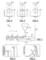
- FIGS. 4 and 5 illustrate the effect of such an additive schematically.
- FIG. 4 shows an illustrative polymer-based foam 50.
- a source of light energy 60 is shown directing an amount of energy E toward polymer-based foam 50.
- FIG. 5 shows an embodiment of a foam layer material 50' that includes the polymer-based foam 50 of FIG. 4 and an additive in an amount sufficient to decrease the amount of light transmission through the material 50' when compared to the polymer-based foam 50.
- the decrease in light transmission through material 50' when compared to polymer-based foam 50 is due to a corresponding increase in light absorption in foam layer material 50'.
- light transmission through the foam layer material may be affected by selecting an additive that increases the reflection of light by the foam layer material when compared to the polymer-based material.
- an additive that increases the reflection of light by the foam layer material when compared to the polymer-based material.
- a particular color of additive e.g., certain white titanium dioxide-based colorants
- any additive may be included in the foam layer material that increases the reflectivity of the material at the characteristic wavelength when compared to the polymer-based foam, whether or not the color of the material is changed due to the additive.
- certain particulate additives known to reflect the characteristic wavelength could be used in the foam layer material. This embodiment is shown schematically in FIG.
- both modes of reducing light transmission through the material may be employed by including an additive that increases light absorption and an additive that increases light reflectivity, or by including an additive that does both.
- Yet other embodiments may include one or more additives that result in an increase in light absorption without significantly affecting light reflection, or in an increase in light reflection without significantly affecting light absorption.
- the light transmission through the foam layer material is reduced by inclusion of the additive at least partially through an increase in either the amount of light absorbed or the amount of light reflected at the characteristic wavelength when compared to the polymer-based material.
- FIG. 7 a schematic of a laser scoring process for use in forming a tear seam 18 in one or more airbag panel components is shown, according to one embodiment.
- the illustrated process uses a laser scoring system 100 that includes a laser light source 102, a sensor 104, and a feedback loop 106, along with means for indexing light source 102 and sensor 104 from one cut location to another.
- Indexing can include moving light source 102 and sensor 104 together in a direction along a cutting path or from one location to another along a cutting pattern (e.g., in the left-to-right direction indicated by the arrow in FIG. 7 ). Indexing can also include moving the covering 16 (shown in cross-section) and/or other panel component in an opposite direction, or it can include moving both the covering and the light source/sensor.
- Light source 102 is positioned to direct a laser light beam 108 toward the desired panel component, in this case toward the inner surface of an embodiment of covering 16.
- the light source 102 is directed toward a substrate (such as substrate 14 of FIGS. 1-3 ), but the substrate has been omitted in FIG. 7 for clarity.
- the laser beam 108 could be used to form a tear seam in the substrate material as well as the covering, or the substrate could include an airbag door gap through which beam 108 passes to reach covering 16.
- the light source 102 may be any type of laser light source, one example of which is a CO 2 laser source that can produce a narrowly focused light beam comprising light energy at a characteristic wavelength.
- CO 2 lasers typically produce light in the mid-infrared range of the electromagnetic spectrum having a wavelength of about 10.6 ⁇ m, but may be constructed to produce light having other wavelengths.
- Other light sources capable of cutting the provided covering materials may be used and may have different characteristic wavelengths that can be used to help select the additive for the foam layer material.
- the characteristic wavelength refers to the nominal wavelength of a light beam but is not limited to a single wavelength.
- the characteristic wavelength may be a range of wavelengths or a wavelength band normally associated with the particular light source.
- Sensor 104 is arranged on an opposite side of the covering 16 from the light source 102, or on the same side as the skin layer 32 in this example. Sensor 104 is located within the projected path of beam 108 and is configured to receive and sense energy from the laser light source 102.
- This example of sensor 104 includes a light sensitive side 110 that faces toward the skin layer 32 to sense light at the characteristic wavelength (or range of wavelengths that includes the characteristic wavelength) emitted by light source 102.
- FIG. 7 is not necessarily to scale, and the physical size of sensor 104 is not limited, sensor 104 is shown in one possible relative size relationship with respect to the distance D between successive laser cuts 44. For example, as already noted, distance D may range from about 0.5 mm to about 5.0 mm.
- sensor 104 is about 25-35 mm in length (side-to-side as oriented in FIG. 7 ). Thus sensor 104, including its light sensitive side 110, may be physically large enough to span a plurality of tear seam cut locations. Sensor 104 in the illustrated embodiment also includes a center line 112 that generally remains in alignment with beam 108 during the scoring process, though it is not necessarily located in the center of the sensor 104.
- source 102 is energized and directs beam 108 toward the covering 16 as shown.
- the beam 108 extends into covering 16 to a distance sufficient to cause the transmission of light through the covering 16 to be greater than zero.
- Sensor 104 detects the intensity or amount of light transmitted through the remaining thickness of covering 16 while each cut 44 is being formed and communicates that information within system 100 via feedback loop 106, which may include one or more processors (not shown) that control system 100 operation.
- System 100 is automated and may be configured to stop cutting or de-energize the laser light source 102 at a particular cut location when sensor 104 detects a pre-determined amount of light being transmitted from source 102 and through the remaining thickness of the covering 16.
- the pre-determined amount of light that results in the desired RWT for a particular covering or panel assembly may be determined experimentally and represented in system 100 as a user-set cut-off voltage.
- the cut-off voltage is one type of setting that informs system 100 at what sensor output voltage (correlated to the amount of light sensed) it should stop cutting at one cut location and move to the next cut location along the cutting path.
- an energy leakage phenomenon can occur.
- a laser cut is being formed at a particular location, such as location B, in the covering 16
- some amount of laser light energy may be transmitted through the foam layer material in a direction having a horizontal component.
- Some of this light may reach a previously formed laser cut at a different nearby location, such as location A, and be transmitted through the RWT at the previously formed cut and toward the sensor 104.
- laser light beam 108 may generally have a very narrow and controlled size as directed at the panel components, as it passes through the covering materials, internal reflection of the light energy can contribute to this energy leakage phenomenon, particularly within the foam layer 34 where the material has a cellular structure that may promote light reflection in multiple random directions.
- This energy leakage and subsequent emission of light toward sensor 104 from locations along the covering that have already been cut can cause the sensor to prematurely reach the user-set cut-off voltage.
- the extraneous light detected by sensor 104 may lead system 100 to believe that the desired cut depth and RWT at the present cut location (location B in the example) has been reached, when in reality the present cut has not yet been fully formed.
- the method may include the step of providing an airbag covering 16 including a skin layer 32 and a foam layer 34, where the layers have surfaces in facial contact with each other, and directing a laser light beam 108 from a laser light source 102 and toward the covering 16 such that the foam layer 34 is located between the light source 102 and the skin layer 32.
- the method may further include successively forming a plurality of laser cuts 44 in the covering 16 at a plurality of spaced apart locations, such as locations A and B, along a pre-determined cutting pattern that corresponds to a desired tear seam location.
- the method includes limiting the amount of energy leakage from the location of each successive cut (e.g., location B) to the location of the previously formed cut (e.g., location A) while forming each successive cut by providing an additive in the foam layer 34 that affects the energy transmission characteristics of the foam layer 34.
- the energy transmission characteristics of the foam layer may be of particular interest at the characteristic wavelength of the laser light beam.
- Various embodiments of the method include steps of selecting the additive based on one or more of the criteria explained above.
- the additive may be included in the foam layer material by adding it to the polymer portion of the polymer-based foam material to arrive at the additive-containing foam layer material.
- the additive may be melt processed with the polymer portion of the material prior to foaming the material or, in cases where the foam material is a reaction product, the colorant or other additive may be dispersed within one component of a multi-component reaction system.
- the amount of additive included in the foam layer material is an amount sufficient to decrease the amount of light transmission through the material at the characteristic wavelength when compared to the polymer-based foam.
- the amount of additive is an amount that is sufficiently low so that it does not substantially alter at least one of the following properties of the polymer-based foam: the density, the stiffness (modulus of elasticity), the compressive stiffness, or the percentage of material elongation at break.
- the additive is present in an amount that increases the laser cutting rate of the material at a particular laser power and duty cycle when compared to the polymer-based foam.
- the additive is present in an amount that causes the depth or distance a laser cut extends into the foam layer material to be higher per unit of applied laser light energy than for the polymer-based foam without the same additive.
- FIG. 8 summarizes experimental data collected during laser scoring of one embodiment of an airbag covering in which the foam layer material includes a black colorant.
- the colorant was present in an amount that increased the cutting rate of the foam layer material 50' when compared to the polymer-based foam 50 in its natural color.
- the same amount of laser light energy was directed at the foam layer of the coverings in a statistically significant number of locations, and the depth of each laser cut was measured.
- the cut depths were averaged for each material 50 and 50' and normalized for purposes of FIG. 8 , where it is shown that laser cut depth was 55% greater per unit energy for the foam layer material 50' having the additive than for the natural color polymer-based foam 50. This is believed to be a manifestation of the increased energy absorption at the characteristic wavelength due to the additive. In other words, more of the applied laser light energy was used to cut the foam material rather than being otherwise directed away from the cut location, such as toward a previously formed cut.
- FIG. 9 shows one possible result of including a light transmission-affecting additive in the foam material layer.
- the horizontal axis generally represents the light sensitive side or surface 110 of the sensor 104 from FIG. 7 .
- the vertical axis generally represents the amount or intensity of light detected by the sensor.
- the vertical axis is positioned at the center line 112 of the sensor, described earlier in conjunction with FIG. 7 .
- the chart shows a theoretical and approximate distribution of light energy that may reach the sensor while laser scoring a covering with a natural color polymer-based foam 50 and a covering with a foam layer material 50', 50" having an additive that reduces light transmission at the characteristic wavelength.
- the area under each curve may generally represent the total amount of light energy received by the sensor at a particular depth of cut for each material. As shown, the total amount of light received by the sensor may be less for the foam layer material having the additive, and the distribution of light received by the sensor may be narrower. Thus, a larger portion of the light reaching the sensor is attributed to the laser cut actually being formed rather than being attributed to energy leakage within the foam layer, allowing for more accurate and repeatable monitoring of cut depth. Accordingly, one embodiment of the method of forming a tear seam includes limiting the energy leakage from one cut location to another cut location and narrowing the distribution of light that is received by the sensor and/or transmitted through the covering while a laser cut is being formed.
- certain vehicle interior applications may benefit from additives that result in a foam color that is darker than natural.
- covering materials may be sewn together or sewn to other components to provide a particular aesthetic.
- material from the foam layer of the covering may become visible through the formed holes, or that small pieces of the foam layer material may be pulled through the covering from the foam layer side to the visible skin layer side by the needle and thread.
- dark-colored skin layer materials are utilized in such applications, additives that result in a dark-colored foam layer can help make any stray foam layer material pieces less visible to vehicle occupants.
- the cutting rate of the material may be decreased when compared to the polymer-based material. While this could increase laser cutting cycle times, it could also increase the precision and repeatability of the cut depth because each applied amount of laser energy removes less material. Though it may seem somewhat counterintuitive to formulate the foam layer material to reflect light that is meant to form laser cuts in the material, such a formulation provides at least one of the same advantages as a foam layer material that is formulated to absorb more of the laser light. Each embodiment helps to confine the laser light to the particular cut location and limits the energy leakage through the material and to other locations along the covering.
- a white titanium dioxide-based colorant may be an effective additive to increase absorption of light at a characteristic wavelength in the ultraviolet portion of the spectrum or to increase reflection of light at a characteristic wavelength in the visible or infrared portion of the spectrum.
Landscapes
- Engineering & Computer Science (AREA)
- Mechanical Engineering (AREA)
- Physics & Mathematics (AREA)
- Optics & Photonics (AREA)
- Plasma & Fusion (AREA)
- Air Bags (AREA)
- Laser Beam Processing (AREA)
Applications Claiming Priority (1)
| Application Number | Priority Date | Filing Date | Title |
|---|---|---|---|
| US13/227,621 US8567815B2 (en) | 2011-09-08 | 2011-09-08 | Limiting energy leakage during laser scoring of vehicle airbag coverings |
Publications (3)
| Publication Number | Publication Date |
|---|---|
| EP2567803A2 true EP2567803A2 (fr) | 2013-03-13 |
| EP2567803A3 EP2567803A3 (fr) | 2013-10-23 |
| EP2567803B1 EP2567803B1 (fr) | 2015-03-18 |
Family
ID=46603763
Family Applications (1)
| Application Number | Title | Priority Date | Filing Date |
|---|---|---|---|
| EP20120179215 Not-in-force EP2567803B1 (fr) | 2011-09-08 | 2012-08-03 | Limitation des fuites d'énergie pendant le rainurage au laser de revêtements d'airbag de véhicule |
Country Status (3)
| Country | Link |
|---|---|
| US (1) | US8567815B2 (fr) |
| EP (1) | EP2567803B1 (fr) |
| CN (1) | CN102990226B (fr) |
Cited By (1)
| Publication number | Priority date | Publication date | Assignee | Title |
|---|---|---|---|---|
| EP3100932A1 (fr) * | 2015-06-03 | 2016-12-07 | Faurecia Interior Systems, Inc. | Appareils de recouvrement d'interstice de garniture intérieure pour véhicules automobiles et procédés de fabrication de ceux-ci |
Families Citing this family (7)
| Publication number | Priority date | Publication date | Assignee | Title |
|---|---|---|---|---|
| WO2013089994A1 (fr) * | 2011-12-15 | 2013-06-20 | Faurecia Interior Systems, Inc. | Lignes de rupture non visibles pour recouvrements de coussin de sécurité gonflable |
| US20150068042A1 (en) * | 2013-09-06 | 2015-03-12 | Faurecia Interior Systems, Inc. | Piercing tool and process for forming airbag tear seams |
| US10137616B2 (en) | 2013-09-30 | 2018-11-27 | Disney Enterprises, Inc. | Fabricating lightweight skin systems for large scale robotic characters |
| DE102014216703A1 (de) * | 2014-08-22 | 2016-02-25 | Magna Interiors (Europe) Gmbh | Vorrichtung zum Schneiden und Perforieren |
| DE102016105567B4 (de) * | 2016-03-24 | 2018-05-24 | Eissmann Automotive Deutschland Gmbh | Verfahren zum Einbringen einer definierten Schwächungslinie mit einem gepulsten Laserstrahl durch Materialabtrag an einem Überzugsmaterial |
| US9789838B1 (en) * | 2016-04-04 | 2017-10-17 | Autoliv Asp, Inc. | Airbag cover weakening patterns and related systems and methods |
| DE102016121644A1 (de) * | 2016-11-11 | 2018-06-14 | Jenoptik Automatisierungstechnik Gmbh | Verfahren und Vorrichtung zur Herstellung einer Schwächungslinie in ein flächenhaftes Werkstück entlang einer vorgegebenen Kontur durch Materialabtrag mittels Laser |
Citations (1)
| Publication number | Priority date | Publication date | Assignee | Title |
|---|---|---|---|---|
| GB1343974A (en) | 1970-02-02 | 1974-01-16 | Inmont Corp | Decorative laminates and their manufacture |
Family Cites Families (9)
| Publication number | Priority date | Publication date | Assignee | Title |
|---|---|---|---|---|
| US5961143A (en) * | 1998-05-11 | 1999-10-05 | Textron Automotive Company | Motor vehicle air bag cover having a skin with perforated score line and a method for manufacture thereof |
| KR20020084173A (ko) * | 2000-03-17 | 2002-11-04 | 팁 엔지니어링 그룹 인코포레이티드 | 에어백 전개 개구용으로 자동차 트림피스에 홈을 형성하는방법 및 장치 |
| DE10254377B3 (de) * | 2002-11-19 | 2004-03-18 | Jenoptik Automatisierungstechnik Gmbh | Verfahren zum Erzeugen einer integrierten Sollbruchlinie in ein flächenhaftes Gebilde |
| JP2004331046A (ja) * | 2003-04-15 | 2004-11-25 | Takata Corp | エアバッグ装置の蓋部材、エアバッグ装置及び車両用内装部材 |
| JP4227851B2 (ja) * | 2003-06-30 | 2009-02-18 | タカタ株式会社 | エアバッグカバーの製造方法 |
| JP4769010B2 (ja) * | 2005-04-06 | 2011-09-07 | 三光合成株式会社 | エアーバッグ装置を備えた自動車用内装カバー |
| DE102006032805A1 (de) * | 2006-07-14 | 2008-01-17 | Bst Safety Textiles Gmbh | Verfahren zum Herstellen einer Naht |
| JP2008110647A (ja) * | 2006-10-30 | 2008-05-15 | Okamoto Ind Inc | 車両用内装材 |
| WO2008104230A1 (fr) * | 2007-03-01 | 2008-09-04 | Thomas Wahl | Procédé de préparation de zone de rupture dans un composant, notamment une partie d'habillage |
-
2011
- 2011-09-08 US US13/227,621 patent/US8567815B2/en not_active Expired - Fee Related
-
2012
- 2012-08-03 EP EP20120179215 patent/EP2567803B1/fr not_active Not-in-force
- 2012-09-03 CN CN201210321977.4A patent/CN102990226B/zh not_active Expired - Fee Related
Patent Citations (1)
| Publication number | Priority date | Publication date | Assignee | Title |
|---|---|---|---|---|
| GB1343974A (en) | 1970-02-02 | 1974-01-16 | Inmont Corp | Decorative laminates and their manufacture |
Cited By (2)
| Publication number | Priority date | Publication date | Assignee | Title |
|---|---|---|---|---|
| EP3100932A1 (fr) * | 2015-06-03 | 2016-12-07 | Faurecia Interior Systems, Inc. | Appareils de recouvrement d'interstice de garniture intérieure pour véhicules automobiles et procédés de fabrication de ceux-ci |
| US9566928B2 (en) | 2015-06-03 | 2017-02-14 | Faurecia Interior Systems, Inc. | Interior trim gap covering apparatuses for motor vehicles and methods for making the same |
Also Published As
| Publication number | Publication date |
|---|---|
| US8567815B2 (en) | 2013-10-29 |
| CN102990226A (zh) | 2013-03-27 |
| EP2567803A3 (fr) | 2013-10-23 |
| EP2567803B1 (fr) | 2015-03-18 |
| CN102990226B (zh) | 2016-03-09 |
| US20130065041A1 (en) | 2013-03-14 |
Similar Documents
| Publication | Publication Date | Title |
|---|---|---|
| EP2567803B1 (fr) | Limitation des fuites d'énergie pendant le rainurage au laser de revêtements d'airbag de véhicule | |
| US9358767B2 (en) | Airbag cover materials for laser scoring | |
| US9457758B2 (en) | Pre-weakened cover for an airbag and method of making | |
| US7000942B2 (en) | Method for introducing a line of weakening with low tearing resistance into an airbag cover and airbag cover produced by this method | |
| US6337461B1 (en) | Airbag cover | |
| US20120223512A1 (en) | Angled tear seams for airbag covers | |
| CN102795190B (zh) | 特别是用于汽车安全气囊的安全气囊盖及其制造方法 | |
| US8807590B2 (en) | Multi-layer vehicle airbag coverings | |
| US20050134023A1 (en) | Trim panel having foam bridge supported hidden tear seam | |
| JP5674575B2 (ja) | エアバッグドアの製造方法 | |
| CN109552241B (zh) | 具有激光形成的撕裂缝的车辆内部面板 | |
| US20160361911A1 (en) | Instrument panel with integral hidden door cover and method of manufacture thereof | |
| US8567814B2 (en) | Patterned weakening of airbag coverings | |
| JP2004331046A (ja) | エアバッグ装置の蓋部材、エアバッグ装置及び車両用内装部材 | |
| US9358697B2 (en) | Non-visible tear seams for airbag coverings | |
| US9421937B2 (en) | Panel with integral hidden door cover and method of manufacture and materials thereof | |
| US7625004B2 (en) | Motor vehicle trim element having weakened areas and methods for the manufacture thereof | |
| US7029025B2 (en) | Tear seam for air bag module | |
| US7093850B2 (en) | Instrument panel with integral hidden door cover and method of manufacture thereof | |
| EP2460696A1 (fr) | Lignes de rupture amélioré pour couvercle de module de coussin gonflable | |
| US20090267329A1 (en) | Invisible Pre-Weakened Seam for an Air Bag Deployment Cover | |
| US8567816B1 (en) | Airbag tear seam shapes | |
| US6827799B2 (en) | Method of producing weakened zones in shaped plastic parts by means of ultra sound cutting |
Legal Events
| Date | Code | Title | Description |
|---|---|---|---|
| PUAI | Public reference made under article 153(3) epc to a published international application that has entered the european phase |
Free format text: ORIGINAL CODE: 0009012 |
|
| AK | Designated contracting states |
Kind code of ref document: A2 Designated state(s): AL AT BE BG CH CY CZ DE DK EE ES FI FR GB GR HR HU IE IS IT LI LT LU LV MC MK MT NL NO PL PT RO RS SE SI SK SM TR |
|
| AX | Request for extension of the european patent |
Extension state: BA ME |
|
| PUAL | Search report despatched |
Free format text: ORIGINAL CODE: 0009013 |
|
| AK | Designated contracting states |
Kind code of ref document: A3 Designated state(s): AL AT BE BG CH CY CZ DE DK EE ES FI FR GB GR HR HU IE IS IT LI LT LU LV MC MK MT NL NO PL PT RO RS SE SI SK SM TR |
|
| AX | Request for extension of the european patent |
Extension state: BA ME |
|
| RIC1 | Information provided on ipc code assigned before grant |
Ipc: B60R 21/2165 20110101ALI20130919BHEP Ipc: B23K 26/40 20060101ALN20130919BHEP Ipc: B29C 59/00 20060101AFI20130919BHEP |
|
| 17P | Request for examination filed |
Effective date: 20140331 |
|
| RBV | Designated contracting states (corrected) |
Designated state(s): AL AT BE BG CH CY CZ DE DK EE ES FI FR GB GR HR HU IE IS IT LI LT LU LV MC MK MT NL NO PL PT RO RS SE SI SK SM TR |
|
| GRAP | Despatch of communication of intention to grant a patent |
Free format text: ORIGINAL CODE: EPIDOSNIGR1 |
|
| RIC1 | Information provided on ipc code assigned before grant |
Ipc: B29C 59/00 20060101AFI20140903BHEP Ipc: B23K 26/40 20140101ALN20140903BHEP Ipc: B60R 21/2165 20110101ALI20140903BHEP |
|
| INTG | Intention to grant announced |
Effective date: 20140924 |
|
| RIC1 | Information provided on ipc code assigned before grant |
Ipc: B23K 26/40 20140101ALN20140916BHEP Ipc: B60R 21/2165 20110101ALI20140916BHEP Ipc: B29C 59/00 20060101AFI20140916BHEP |
|
| INTG | Intention to grant announced |
Effective date: 20140930 |
|
| GRAS | Grant fee paid |
Free format text: ORIGINAL CODE: EPIDOSNIGR3 |
|
| GRAA | (expected) grant |
Free format text: ORIGINAL CODE: 0009210 |
|
| AK | Designated contracting states |
Kind code of ref document: B1 Designated state(s): AL AT BE BG CH CY CZ DE DK EE ES FI FR GB GR HR HU IE IS IT LI LT LU LV MC MK MT NL NO PL PT RO RS SE SI SK SM TR |
|
| REG | Reference to a national code |
Ref country code: GB Ref legal event code: FG4D |
|
| REG | Reference to a national code |
Ref country code: CH Ref legal event code: EP |
|
| REG | Reference to a national code |
Ref country code: IE Ref legal event code: FG4D |
|
| REG | Reference to a national code |
Ref country code: AT Ref legal event code: REF Ref document number: 716265 Country of ref document: AT Kind code of ref document: T Effective date: 20150415 |
|
| REG | Reference to a national code |
Ref country code: DE Ref legal event code: R096 Ref document number: 602012005933 Country of ref document: DE Effective date: 20150430 |
|
| REG | Reference to a national code |
Ref country code: NL Ref legal event code: VDEP Effective date: 20150318 |
|
| REG | Reference to a national code |
Ref country code: NL Ref legal event code: VDEP Effective date: 20150318 |
|
| PG25 | Lapsed in a contracting state [announced via postgrant information from national office to epo] |
Ref country code: HR Free format text: LAPSE BECAUSE OF FAILURE TO SUBMIT A TRANSLATION OF THE DESCRIPTION OR TO PAY THE FEE WITHIN THE PRESCRIBED TIME-LIMIT Effective date: 20150318 Ref country code: NO Free format text: LAPSE BECAUSE OF FAILURE TO SUBMIT A TRANSLATION OF THE DESCRIPTION OR TO PAY THE FEE WITHIN THE PRESCRIBED TIME-LIMIT Effective date: 20150618 Ref country code: FI Free format text: LAPSE BECAUSE OF FAILURE TO SUBMIT A TRANSLATION OF THE DESCRIPTION OR TO PAY THE FEE WITHIN THE PRESCRIBED TIME-LIMIT Effective date: 20150318 Ref country code: LT Free format text: LAPSE BECAUSE OF FAILURE TO SUBMIT A TRANSLATION OF THE DESCRIPTION OR TO PAY THE FEE WITHIN THE PRESCRIBED TIME-LIMIT Effective date: 20150318 Ref country code: SE Free format text: LAPSE BECAUSE OF FAILURE TO SUBMIT A TRANSLATION OF THE DESCRIPTION OR TO PAY THE FEE WITHIN THE PRESCRIBED TIME-LIMIT Effective date: 20150318 |
|
| REG | Reference to a national code |
Ref country code: AT Ref legal event code: MK05 Ref document number: 716265 Country of ref document: AT Kind code of ref document: T Effective date: 20150318 |
|
| REG | Reference to a national code |
Ref country code: FR Ref legal event code: PLFP Year of fee payment: 4 |
|
| REG | Reference to a national code |
Ref country code: LT Ref legal event code: MG4D |
|
| PG25 | Lapsed in a contracting state [announced via postgrant information from national office to epo] |
Ref country code: LV Free format text: LAPSE BECAUSE OF FAILURE TO SUBMIT A TRANSLATION OF THE DESCRIPTION OR TO PAY THE FEE WITHIN THE PRESCRIBED TIME-LIMIT Effective date: 20150318 Ref country code: RS Free format text: LAPSE BECAUSE OF FAILURE TO SUBMIT A TRANSLATION OF THE DESCRIPTION OR TO PAY THE FEE WITHIN THE PRESCRIBED TIME-LIMIT Effective date: 20150318 Ref country code: GR Free format text: LAPSE BECAUSE OF FAILURE TO SUBMIT A TRANSLATION OF THE DESCRIPTION OR TO PAY THE FEE WITHIN THE PRESCRIBED TIME-LIMIT Effective date: 20150619 |
|
| PG25 | Lapsed in a contracting state [announced via postgrant information from national office to epo] |
Ref country code: NL Free format text: LAPSE BECAUSE OF FAILURE TO SUBMIT A TRANSLATION OF THE DESCRIPTION OR TO PAY THE FEE WITHIN THE PRESCRIBED TIME-LIMIT Effective date: 20150318 |
|
| PG25 | Lapsed in a contracting state [announced via postgrant information from national office to epo] |
Ref country code: SK Free format text: LAPSE BECAUSE OF FAILURE TO SUBMIT A TRANSLATION OF THE DESCRIPTION OR TO PAY THE FEE WITHIN THE PRESCRIBED TIME-LIMIT Effective date: 20150318 Ref country code: PT Free format text: LAPSE BECAUSE OF FAILURE TO SUBMIT A TRANSLATION OF THE DESCRIPTION OR TO PAY THE FEE WITHIN THE PRESCRIBED TIME-LIMIT Effective date: 20150720 Ref country code: ES Free format text: LAPSE BECAUSE OF FAILURE TO SUBMIT A TRANSLATION OF THE DESCRIPTION OR TO PAY THE FEE WITHIN THE PRESCRIBED TIME-LIMIT Effective date: 20150318 Ref country code: RO Free format text: LAPSE BECAUSE OF FAILURE TO SUBMIT A TRANSLATION OF THE DESCRIPTION OR TO PAY THE FEE WITHIN THE PRESCRIBED TIME-LIMIT Effective date: 20150318 Ref country code: EE Free format text: LAPSE BECAUSE OF FAILURE TO SUBMIT A TRANSLATION OF THE DESCRIPTION OR TO PAY THE FEE WITHIN THE PRESCRIBED TIME-LIMIT Effective date: 20150318 Ref country code: CZ Free format text: LAPSE BECAUSE OF FAILURE TO SUBMIT A TRANSLATION OF THE DESCRIPTION OR TO PAY THE FEE WITHIN THE PRESCRIBED TIME-LIMIT Effective date: 20150318 |
|
| PG25 | Lapsed in a contracting state [announced via postgrant information from national office to epo] |
Ref country code: PL Free format text: LAPSE BECAUSE OF FAILURE TO SUBMIT A TRANSLATION OF THE DESCRIPTION OR TO PAY THE FEE WITHIN THE PRESCRIBED TIME-LIMIT Effective date: 20150318 Ref country code: AT Free format text: LAPSE BECAUSE OF FAILURE TO SUBMIT A TRANSLATION OF THE DESCRIPTION OR TO PAY THE FEE WITHIN THE PRESCRIBED TIME-LIMIT Effective date: 20150318 Ref country code: IS Free format text: LAPSE BECAUSE OF FAILURE TO SUBMIT A TRANSLATION OF THE DESCRIPTION OR TO PAY THE FEE WITHIN THE PRESCRIBED TIME-LIMIT Effective date: 20150718 |
|
| REG | Reference to a national code |
Ref country code: DE Ref legal event code: R097 Ref document number: 602012005933 Country of ref document: DE |
|
| PG25 | Lapsed in a contracting state [announced via postgrant information from national office to epo] |
Ref country code: IT Free format text: LAPSE BECAUSE OF FAILURE TO SUBMIT A TRANSLATION OF THE DESCRIPTION OR TO PAY THE FEE WITHIN THE PRESCRIBED TIME-LIMIT Effective date: 20150318 |
|
| PLBE | No opposition filed within time limit |
Free format text: ORIGINAL CODE: 0009261 |
|
| STAA | Information on the status of an ep patent application or granted ep patent |
Free format text: STATUS: NO OPPOSITION FILED WITHIN TIME LIMIT |
|
| PG25 | Lapsed in a contracting state [announced via postgrant information from national office to epo] |
Ref country code: DK Free format text: LAPSE BECAUSE OF FAILURE TO SUBMIT A TRANSLATION OF THE DESCRIPTION OR TO PAY THE FEE WITHIN THE PRESCRIBED TIME-LIMIT Effective date: 20150318 |
|
| 26N | No opposition filed |
Effective date: 20151221 |
|
| PG25 | Lapsed in a contracting state [announced via postgrant information from national office to epo] |
Ref country code: SI Free format text: LAPSE BECAUSE OF FAILURE TO SUBMIT A TRANSLATION OF THE DESCRIPTION OR TO PAY THE FEE WITHIN THE PRESCRIBED TIME-LIMIT Effective date: 20150318 |
|
| PG25 | Lapsed in a contracting state [announced via postgrant information from national office to epo] |
Ref country code: MC Free format text: LAPSE BECAUSE OF FAILURE TO SUBMIT A TRANSLATION OF THE DESCRIPTION OR TO PAY THE FEE WITHIN THE PRESCRIBED TIME-LIMIT Effective date: 20150318 Ref country code: LU Free format text: LAPSE BECAUSE OF FAILURE TO SUBMIT A TRANSLATION OF THE DESCRIPTION OR TO PAY THE FEE WITHIN THE PRESCRIBED TIME-LIMIT Effective date: 20150803 |
|
| REG | Reference to a national code |
Ref country code: CH Ref legal event code: PL |
|
| PG25 | Lapsed in a contracting state [announced via postgrant information from national office to epo] |
Ref country code: CH Free format text: LAPSE BECAUSE OF NON-PAYMENT OF DUE FEES Effective date: 20150831 Ref country code: LI Free format text: LAPSE BECAUSE OF NON-PAYMENT OF DUE FEES Effective date: 20150831 |
|
| REG | Reference to a national code |
Ref country code: IE Ref legal event code: MM4A |
|
| PG25 | Lapsed in a contracting state [announced via postgrant information from national office to epo] |
Ref country code: IE Free format text: LAPSE BECAUSE OF NON-PAYMENT OF DUE FEES Effective date: 20150803 |
|
| REG | Reference to a national code |
Ref country code: FR Ref legal event code: PLFP Year of fee payment: 5 |
|
| PG25 | Lapsed in a contracting state [announced via postgrant information from national office to epo] |
Ref country code: BE Free format text: LAPSE BECAUSE OF FAILURE TO SUBMIT A TRANSLATION OF THE DESCRIPTION OR TO PAY THE FEE WITHIN THE PRESCRIBED TIME-LIMIT Effective date: 20150318 |
|
| PG25 | Lapsed in a contracting state [announced via postgrant information from national office to epo] |
Ref country code: MT Free format text: LAPSE BECAUSE OF FAILURE TO SUBMIT A TRANSLATION OF THE DESCRIPTION OR TO PAY THE FEE WITHIN THE PRESCRIBED TIME-LIMIT Effective date: 20150318 |
|
| GBPC | Gb: european patent ceased through non-payment of renewal fee |
Effective date: 20160803 |
|
| PG25 | Lapsed in a contracting state [announced via postgrant information from national office to epo] |
Ref country code: BG Free format text: LAPSE BECAUSE OF FAILURE TO SUBMIT A TRANSLATION OF THE DESCRIPTION OR TO PAY THE FEE WITHIN THE PRESCRIBED TIME-LIMIT Effective date: 20150318 Ref country code: HU Free format text: LAPSE BECAUSE OF FAILURE TO SUBMIT A TRANSLATION OF THE DESCRIPTION OR TO PAY THE FEE WITHIN THE PRESCRIBED TIME-LIMIT; INVALID AB INITIO Effective date: 20120803 Ref country code: SM Free format text: LAPSE BECAUSE OF FAILURE TO SUBMIT A TRANSLATION OF THE DESCRIPTION OR TO PAY THE FEE WITHIN THE PRESCRIBED TIME-LIMIT Effective date: 20150318 |
|
| PG25 | Lapsed in a contracting state [announced via postgrant information from national office to epo] |
Ref country code: CY Free format text: LAPSE BECAUSE OF FAILURE TO SUBMIT A TRANSLATION OF THE DESCRIPTION OR TO PAY THE FEE WITHIN THE PRESCRIBED TIME-LIMIT Effective date: 20150318 |
|
| PG25 | Lapsed in a contracting state [announced via postgrant information from national office to epo] |
Ref country code: GB Free format text: LAPSE BECAUSE OF NON-PAYMENT OF DUE FEES Effective date: 20160803 |
|
| REG | Reference to a national code |
Ref country code: FR Ref legal event code: PLFP Year of fee payment: 6 |
|
| PG25 | Lapsed in a contracting state [announced via postgrant information from national office to epo] |
Ref country code: TR Free format text: LAPSE BECAUSE OF FAILURE TO SUBMIT A TRANSLATION OF THE DESCRIPTION OR TO PAY THE FEE WITHIN THE PRESCRIBED TIME-LIMIT Effective date: 20150318 |
|
| PGFP | Annual fee paid to national office [announced via postgrant information from national office to epo] |
Ref country code: FR Payment date: 20170825 Year of fee payment: 6 |
|
| PG25 | Lapsed in a contracting state [announced via postgrant information from national office to epo] |
Ref country code: MK Free format text: LAPSE BECAUSE OF FAILURE TO SUBMIT A TRANSLATION OF THE DESCRIPTION OR TO PAY THE FEE WITHIN THE PRESCRIBED TIME-LIMIT Effective date: 20150318 |
|
| PG25 | Lapsed in a contracting state [announced via postgrant information from national office to epo] |
Ref country code: AL Free format text: LAPSE BECAUSE OF FAILURE TO SUBMIT A TRANSLATION OF THE DESCRIPTION OR TO PAY THE FEE WITHIN THE PRESCRIBED TIME-LIMIT Effective date: 20150318 |
|
| PG25 | Lapsed in a contracting state [announced via postgrant information from national office to epo] |
Ref country code: FR Free format text: LAPSE BECAUSE OF NON-PAYMENT OF DUE FEES Effective date: 20180831 |
|
| PGFP | Annual fee paid to national office [announced via postgrant information from national office to epo] |
Ref country code: DE Payment date: 20210720 Year of fee payment: 10 |
|
| REG | Reference to a national code |
Ref country code: DE Ref legal event code: R119 Ref document number: 602012005933 Country of ref document: DE |
|
| PG25 | Lapsed in a contracting state [announced via postgrant information from national office to epo] |
Ref country code: DE Free format text: LAPSE BECAUSE OF NON-PAYMENT OF DUE FEES Effective date: 20230301 |