EP2567836B2 - Attelage - Google Patents
Attelage Download PDFInfo
- Publication number
- EP2567836B2 EP2567836B2 EP12183766.0A EP12183766A EP2567836B2 EP 2567836 B2 EP2567836 B2 EP 2567836B2 EP 12183766 A EP12183766 A EP 12183766A EP 2567836 B2 EP2567836 B2 EP 2567836B2
- Authority
- EP
- European Patent Office
- Prior art keywords
- pivot
- locking
- carrier
- unit
- actuating
- Prior art date
- Legal status (The legal status is an assumption and is not a legal conclusion. Google has not performed a legal analysis and makes no representation as to the accuracy of the status listed.)
- Active
Links
Images







Classifications
-
- B—PERFORMING OPERATIONS; TRANSPORTING
- B60—VEHICLES IN GENERAL
- B60D—VEHICLE CONNECTIONS
- B60D1/00—Traction couplings; Hitches; Draw-gear; Towing devices
- B60D1/01—Traction couplings or hitches characterised by their type
- B60D1/06—Ball-and-socket hitches
-
- B—PERFORMING OPERATIONS; TRANSPORTING
- B60—VEHICLES IN GENERAL
- B60D—VEHICLE CONNECTIONS
- B60D1/00—Traction couplings; Hitches; Draw-gear; Towing devices
- B60D1/48—Traction couplings; Hitches; Draw-gear; Towing devices characterised by the mounting
- B60D1/54—Traction couplings; Hitches; Draw-gear; Towing devices characterised by the mounting collapsible or retractable when not in use, e.g. hide-away hitches
Definitions
- the invention relates to a trailer coupling comprising a holding unit that can be firmly connected to a vehicle body, a swivel bearing unit provided on the holding unit with a swivel bearing base firmly connected to the holding unit and with a swivel bearing base that can be swiveled relative to the swivel bearing base about a swivel axis between a working position and a rest position and be displaceable in the direction of the swivel axis Swivel element, a ball neck held at one end on the swivel element, which carries a coupling ball at the other end and which can be swiveled around the swivel axis between the working position and the rest position due to the swiveling ability of the swivel element.
- trailer hitches are from the prior art, for example from EP 1 902 870 A1 known.
- the locking receptacle is provided with a retraction surface on which the locking body can act before reaching the locking position to retract the receiving carrier and thus the pivoting element into the fixing position, and that the retraction surface extends so far that the locking element on this in can act in the release position, when in the release position it is acted upon in the direction of the locking position, so that the locking element can be used to pull the receiving carrier into the fixing position starting from the pivoted position and it is also possible in the Pivoting a pull-in force to act on the receiving support.
- the central receiving carrier has at least two locking receptacles, that at least two locking elements are arranged in the space around the central receiving carrier and that the guide carrier has at least two guides for the at least two locking elements.
- the actuating element for one or more locking elements so that it can be moved in the radial direction to the pivot axis or to arrange it so that it can be moved in the direction parallel to the pivot axis.
- the actuating element can be rotated about the pivot axis and has at least one actuation surface sequence which comprises a maximally radially outer and a maximally radially inner surface area and that the at least one locking element when in contact with the radially maximally outer surface area is in its release position and is in its locking position when it is in contact with the radially maximally inner surface area.
- the actuating element surrounds the receiving carrier and the at least two locking elements in a radially outer manner.
- an advantageous solution provides that the actuating element has an annular actuating surface carrier on which the at least one actuating surface sequence is arranged.
- the actuating element is constantly urged in the direction of its locking position by a spring force accumulator. This has the particular advantage that the locking unit in the event of non-actuation, it automatically changes from any position into the locking position, in particular a clamping position thereof.
- This solution has the advantage that a movement of the actuating element in the direction of the release position has to take place against the action of the spring force accumulator and thus, if the actuating element is not actuated, it always automatically moves into the locking position and thus moves the locking elements into the locking receptacles, so that the The system always automatically changes to a safe, namely locked state, provided that the swivel element reaches the fixing position.
- the actuating element can be fixed in its locking position against movement into its release position by a securing unit.
- the actuating element can be actuated via a rotary entrainment element that can be moved from an initial position into a driving position.
- Such a rotary driving element opens up the possibility of acting indirectly on the actuating element and thus ensuring, for example, that the actuating element has the possibility of always moving into its locking position.
- a rotary drive element allows the securing unit to be actuated.
- the securing unit can be moved from an unlocking position into a securing position by means of the rotary drive element.
- the rotary drive element allows the securing unit to transition into the unlocking position at the latest when the actuating element is actuated to move it from the locking position to the release position.
- the rotary drive element transfers the securing unit into the unlocked position before it acts on the actuating element, so that when the actuating element is acted on it can be moved without blocking by the securing unit.
- the securing unit is preferably designed in such a way that it comprises a securing element which is acted upon by a spring force accumulator in the direction of its unlocking position, so that the rotary driving element acts on the securing element in such a way that it passes into the securing position when it is acted upon by the rotary driving element and upon a corresponding movement of the rotary drive element has the opportunity to move into the unlocked position due to the spring force accumulator.
- a rotary driver element In order to ensure, when a rotary driver element is provided, that the rotary driver element always moves into its starting position, in which it holds the securing unit in particular, it is preferably provided that the rotary driver element is acted upon by a spring force storage device in the direction of a starting position.
- the rotary drive element allows a free rotary movement of the actuating element in the direction of its locking position, the permitted rotational movement of the actuating element according to the design of the actuation surface sequence including a free movement of the actuating element in the direction of a locking position and in particular in the locking position in the direction of a clamping position in which the actuating element acts on the locking element with the respective locking receptacle and the respective guide in a bracing manner.
- the axially acting locking unit has an axially in Has the direction of the pivot position acting pushing unit.
- Such a push-out unit can be designed in the most varied of ways.
- the pushing-out unit preferably comprises a pushing-out element which acts in the direction of the swivel axis and with which the swivel element can be displaced from the fixing position into the swiveling position.
- Such a push-out element is implemented, for example, in such a way that it acts on a pressure receiving element coupled to the pivoting element, for example by means of an inclined surface.
- the pushing-out element with the pressure-receiving element then moves the pivoting element from the fixing position into the pivoting position when the at least one locking element can reach its release position, which means that the actuating element in particular is then in its release position.
- one advantageous solution provides that the locking element is supported on the guide in the locking position and can thus be pressed into the locking receptacle with support on the guide in order to be able to brace the receiving carrier in the locking position relative to the guide carrier by means of the locking element, so that through the locking element acted upon in its locking position by the actuating element, the receiving carrier can be braced relative to the guide carrier.
- the guide in such a way that it is implemented by a bore or a closed channel in the guide support.
- a particularly advantageous solution which is simplified in particular with regard to production and assembly, provides that the at least one guide is formed by a recess in the guide support.
- Such a recess is, for example, designed like a groove and has mutually opposite side walls and a recess base, which preferably guide the locking element in the intended direction of movement.
- the recess is designed so that the locking element is supported in its locking position engaging the locking receptacle on a bottom of the recess and thus in the locking position on the one hand rests against the bottom of the recess, on the other hand rests in the locking receptacle and furthermore still by the actuating element in Direction of the locking position is applied.
- An advantageous solution provides that the guide carrier and a fixed form-fit element carrier of the fixing unit are connected to one another.
- One solution that is particularly expedient for production provides that the guide is arranged on a side opposite the form-fit elements of the fixed form-fit element carrier.
- the swivel element has a central swivel bearing body which can be swiveled around the swivel axis and in the direction of the swivel axis between the swivel position in a swivel bearing body receptacle of the swivel bearing base that surrounds it radially on the outside and the fixing position is slidably mounted.
- the swivel bearing body carries a central receiving carrier of the axially acting locking unit which has at least one locking receptacle and which is immovably connected to the swivel bearing body in the direction of the swivel axis.
- the locking unit can preferably be implemented in such a way that at least one locking element of the axially acting locking unit is arranged in a space around the receiving carrier, that a guide carrier supported on the swivel bearing base is guided in a guide and through one on a side facing away from the receiving carrier of the locking element arranged actuating element with the at least one locking receptacle in engagement or disengagement.
- Such a solution is particularly compact and allows the locking unit to be integrated into the pivot bearing unit in a simple manner.
- the pivot bearing body and the receiving carrier are preferably firmly connected to one another.
- pivot bearing body and the receiving carrier form an integral part.
- a stationary form-fit element carrier of the fixing unit is arranged radially on the outside in a region of the swivel bearing base that extends around the swivel bearing body.
- a form-fit element carrier pivoting with the pivot element is firmly connected to the pivot bearing body.
- the swiveling swivel element carrier is fixedly connected to a swivel bearing head.
- the interlocking element carrier pivoting with it is integrally formed on the pivot bearing head.
- Another advantageous solution provides that the locking unit can be actuated by an actuating motor.
- Such an actuation by an actuating motor only takes place in the sense that the locking unit is transferred into the release position and the actuation is then set again with the actuating motor, so that the locking unit automatically switches from the release position to the locking position, in particular to the clamping position transforms.
- the locking unit is provided with a separate energy storage device, in particular a spring force storage device, which generates the transition from the release position to the locking position and the actuating motor then also acts against this energy storage device during the transition from the locking position to the release position.
- a separate energy storage device in particular a spring force storage device, which generates the transition from the release position to the locking position and the actuating motor then also acts against this energy storage device during the transition from the locking position to the release position.
- the swivel element can be swiveled by a swivel motor between the drive position and the rest position, so that there is no longer any manual swiveling, but this swiveling is done by the swivel motor, which in turn is only for the pivoting movement is required.
- the fixing unit has a fixed first tooth segment firmly connected to the pivot bearing base, with which a first tooth segment connected to the pivot element in a rotationally fixed manner and pivoting with it in the working position can be brought into engagement by shifting the pivot element from the pivot position into the fixing position and can be brought out of engagement by shifting from the fixing position into the pivot position.
- a toothed segment is not to be understood as a toothed ring revolving around the pivot axis, but rather a segment of such a toothed ring.
- Such a tooth segment preferably extends over an arc segment of a maximum of 180 °, preferably a maximum of 120 °, around the pivot axis.
- the fixing unit has a further first toothed segment that is fixedly connected to the swivel bearing base or non-rotatably connected to the swivel element, with which the swiveling or swiveling element is connected to the swivel element.
- the first tooth segment fixedly connected to the pivot bearing base can be brought into engagement in the rest position by shifting the pivot element from the pivot position into the fixing position and can be brought out of engagement by shifting from the fixing position into the pivot position.
- the fixing unit has a stationary second tooth segment that is firmly connected to the pivot bearing base and with which a second tooth segment that is non-rotatably connected to the pivot element and pivots with the pivot element
- the working position can be brought into engagement by moving the pivoting element from the pivoting position into the fixing position and can be disengaged by moving the pivoting element from the fixing position into the pivoting position.
- the stability of the fixation by the first tooth segments and the second tooth segments can preferably be further improved if the first tooth segments and the second tooth segments are each arranged essentially opposite one another relative to the pivot axis, so that on both sides the pivot axis a rotationally fixed fixation of the pivot element relative to the pivot bearing base takes place.
- a center of the first tooth segment and the corresponding second tooth segment are rotated relative to one another by an angular distance of 150 ° to 210 °.
- the fixing unit has a further second tooth segment that is fixedly connected to the swivel bearing base or non-rotatably connected to the swivel element, with which the second tooth segment is non-rotatably connected to the swivel element and the second toothed segment which pivots with the pivot element or the second tooth segment firmly connected to the pivot bearing base can be brought into engagement in the rest position by moving the pivot element from the pivot position into the fixing position and disengaged by moving the pivot element from the fixing position into the pivot position.
- the further first and second tooth segments should be fixed first and second tooth segments or that instead of the further fixed first and second tooth segments, further pivotable first and second tooth segments can be provided in order to fix in the rest position to achieve the pivot element relative to the pivot bearing base.
- the further tooth segments are not firmly connected to the pivot bearing base, but are instead firmly connected to the pivot element.
- first tooth segments are arranged at a first radial distance from the pivot axis and the second tooth segments are arranged at a second radial distance from the pivot axis, which differs from the first radial distance, so that the first tooth segments and the second tooth segments when moving of the pivot element can be moved to one another without collision about the pivot axis and in the direction of the pivot axis.
- first and second tooth segments cannot be mutually brought into engagement with one another but only first tooth segments can be brought into engagement with first tooth segments and second tooth segments can be brought into engagement with second tooth segments.
- one advantageous solution provides that the first tooth segment, which can be swiveled with the swivel element, is held on a form-fit element carrier of the swivel element.
- a form-fit element carrier allows the toothed segments to be positioned in a simple manner, the form-fit element carrier then being connectable to the pivot element in a simple manner.
- first toothed segment that can be pivoted with it is formed in one piece on the form-fit element carrier of the pivot element.
- one advantageous solution provides that the fixed first toothed segment is fixedly arranged on a form-locking element carrier that is fixedly connected to the pivot bearing base.
- the stationary first tooth segment is integrally formed on the interlocking element carrier.
- first tooth segment it is also provided that it is fixedly arranged on the respective form-fit element carrier.
- the further first tooth segment is held in a form-fitting manner on the respective form-fitting element carrier and can thus be easily positioned in accordance with the intended rest position.
- the swiveling second tooth segment it is preferably provided that it is held on the form-fit element carrier of the swivel element in the same way as the swiveling first tooth segment.
- the second toothed segment which swivels with it is formed in one piece on the form-fit element carrier of the swivel element.
- the stationary tooth segment is arranged in a stationary manner on the form-fit element carrier that is firmly connected to the pivot bearing base.
- the stationary second tooth segment is integrally formed on the form-fit element carrier.
- the further second tooth segment is fixedly arranged on the respective form-fit element carrier, the further second tooth segment preferably being held in a form-fit manner on the respective form-fit element carrier and thus also easily positionable in accordance with the rest position.
- the illustrated motor vehicle designated as a whole by 10, comprises a vehicle body 12, on which a trailer coupling 20 according to the invention is mounted on a rear region 14, which is a cross member 22 which is covered by a bumper unit 16 and extends transversely to a longitudinal direction of the vehicle body 12 and transversely to the rear region 14 and side members 24 which extend in the longitudinal direction of the vehicle body 12 along body wall sections and are fixed to them, which together with the cross member 22 form a holding unit 26 which is partly covered by the vehicle body 12 and partly by the bumper unit 16.
- a holding plate 32 of a pivot bearing unit designated as a whole as 30 is provided, with which a ball neck designated as a whole as 40 is connected to a first end 42 which also carries a coupling ball designated as a whole as 46 at a second end 44, as in Fig. 1 and 2 shown.
- the pivot bearing unit 30 makes it possible to mount the ball neck 40 from an in Fig. 2 and 3 working position A shown, in which a ball center axis 48 of the coupling ball 46 is in a vehicle longitudinal center plane FL, about a pivot axis 50 running transversely, in particular obliquely, preferably at an acute angle to the vehicle longitudinal center plane FL into a pivot axis 50 in Fig. 4 shown rest position R closed pivot, in which a central section 52 of the ball neck extends transversely to the vehicle longitudinal center plane FL and the coupling ball 46 lies to the side of the vehicle longitudinal center plane FL ( Fig. 4 ).
- the ball neck 40 is preferably arranged in the rest position R in a position covered by the bumper unit 16 of the vehicle body 12 to the side of the vehicle longitudinal center plane FL and - depending on the orientation of the pivot axis 50 - the ball neck 40 lies on a side of the coupling ball 46 or the side facing away from a roadway 54 the ball neck 40 lies at least at such a distance from the roadway 54 that it lies higher than a lower edge 56 of the bumper unit 16 from the roadway 54.
- the swivel bearing unit designated as a whole by 30 is arranged, for example, on the holding plate 32 of the holding unit 26 such that the swivel axis 50 runs perpendicular to the holding plate 32, for example the swivel bearing unit 30 according to the invention extending on both sides of the holding plate 32.
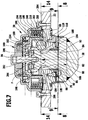
- the pivot bearing unit 30 comprises a pivot bearing base 60 which, for example, is inserted into an opening 62 of the retaining plate 32 and connected to the retaining plate 32 by joining and which forms a central passage 64 which is enclosed at least in part by a pivot bearing body receptacle 66 designed as a sleeve .
- the swivel bearing body receptacle 66 which is designed as a sleeve, is preferably located in a recess 68 which receives the swivel bearing body receptacle 66 and is formed in the swivel bearing base 60 and adjoins a front side 70 of the swivel bearing base 60.
- a swivel element 80 can be swiveled about the swivel axis 50 and has a swivel bearing body 82 which engages in the passage 64 and passes through the passage 64 of the swivel bearing base 60.
- the pivot bearing body 82 has in the area of an outer end 84 an outer bearing section 86 which carries cylindrical outer guide surfaces 88 which interact with cylindrical guide surfaces 92 of the pivot bearing body receptacle 66, so that the cylindrical guide surfaces 88 and 92 are arranged coaxially to the pivot axis 50 and an outer one Form pivot bearing for the pivot bearing body 82.
- the pivot bearing body 82 extends from the outer end 84 through the passage 64 and forms at an inner end 94 an inner bearing section 96 in the form of a pin, which carries cylindrical inner guide surfaces 98, which with cylindrical guide surfaces 102 also coaxially around the Pivot axis 50 form rotatable inner pivot bearing, the guide surfaces 102 being arranged on a housing body 100 which is firmly connected to the holding plate 30 and thus also firmly to the pivot bearing base 60.
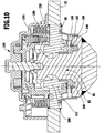
- the pivot member 80 is of a in Fig. 6 shown fixing position in the direction of the pivot axis in a in Fig. 7
- the illustrated release position is displaceable, wherein in the release position the pivot element 80 is shifted in the direction of the pivot axis 50 such that the outer end 84 of the pivot bearing body 82 at least partially protrudes beyond the front side 70 of the pivot bearing base 60, i.e. the pivot bearing body 82 as a whole in the direction of the front side 70 is shifted.
- the pivot bearing body 82 is, however, also in the pivot position both with the inner bearing section 96, comprising the inner guide surface 98, guided in the guide surface 102 coaxially to the pivot axis 50 and with the outer bearing section 86, comprising the outer guide surface 88, in the guide surface 92 of the Swivel bearing body receptacle 66, guided coaxially to the swivel axis 50.
- the pivot bearing unit 30 allows both a pivoting of the pivot element 80 and a displacement of the pivot element 80 in the direction of the pivot axis 50, with the pivot bearing body 82 being guided rotatably about the pivot axis 50 both in the fixing position and in the pivot position.
- the outer guide surface 88 preferably has a larger diameter than the inner guide surface 98 and is guided in the corresponding guide surface 92 with a larger diameter than the inner guide surface 98 in the guide surface 102, so that the outer guide surface formed by the outer guide surface 88 and the guide surface 92 Pivot bearing is able to absorb greater forces than the inner pivot bearing formed by the inner guide surface 98 and the guide surface 102, wherein in particular the inner pivot bearing primarily represents a guide against tilting of the outer guide surface 88 in the guide surface 92 of the outer pivot bearing.
- a fixing unit designated as a whole by 110 is provided.
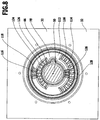
- This fixing unit 110 comprises, as in FIG Fig. 6 and 8th shown, a radially outside of the pivot bearing body receptacle 66 and the front side 70 of the pivot bearing base 60 forming form-fit element carrier 112, which as a form-fit element has a radially outer first tooth segment 114 with first teeth 116 that rise above the front side 70, the first tooth segment 114 with a A plurality of the first teeth 116 is provided, which extend, for example, over an arc segment of more than 90 °, for example an arc segment of up to 120 °, about the pivot axis 50.
- a further first toothed segment 118 is provided as a positive-locking element on the positive-locking element carrier 112, which also has first teeth 116, but only a few first teeth, for example three such first teeth 116, so that the further first toothed segment extends only over an arcuate section which is substantially is smaller than the arcuate portion of the first tooth segment.
- the two first tooth segments 114 and 118 run at the same radial distance around the pivot axis 50.
- a radially inner second tooth segment 124 is provided opposite the first tooth segment 114 on the form-fit element carrier, which is arranged, for example, between the radially outer further first tooth segment 118 and the pivot bearing body receptacle 66 on the front side 70.
- This second tooth segment 124 also has a multiplicity of second teeth 126 and extends over an arcuate section of more than 90 °, preferably over an arcuate section which in its extension roughly corresponds to that of the first tooth segment 114.
- a further second tooth segment 128 is preferably provided between the first tooth segment 114 and the pivot bearing body receptacle 66 on the form-fit element carrier 112, which also has second teeth 126, but extends over a significantly smaller arcuate section than the second tooth segment 126, for example three second teeth 126 includes.
- the two second tooth segments 114, 118 run at the same radial distance around the pivot axis 50, which, however, is smaller than the radial distance between the first tooth segments 114, 118 from the pivot axis 50.
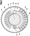
- the fixing unit 110 comprises an in Fig. 9 shown with the swivel element 80 moveable form-fit element carrier 132, which is arranged on a swivel bearing body head 130 protruding radially over the swivel bearing body 82 and the front side 70 of the swivel bearing base 60 overlapping.
- the form-fit element carrier 132 in turn has a radially outer first tooth segment 134 with first teeth 136, as well as a radially inner second tooth segment 144 with second teeth 146, the first tooth segment 134 and the second tooth segment 144 being arranged opposite one another in relation to the pivot axis 50 and wherein the radial distance between the first tooth segment 134 and the radial distance between the second tooth segment 144 and the pivot axis 50 correspond to the radial distances between the corresponding tooth segments 114, 118 and 124, 128 of the interlocking element carrier 112.
- the first tooth segment 134 and the second tooth segment 144 are preferably formed in one piece on the movable form-fit element carrier 132 and the movable form-fit element carrier 132 is formed in one piece on the pivot bearing body head 130, so that ultimately the tooth segments 134 and 144 are integrally connected to the pivot bearing body 82 are.
- the first tooth segment 114 and the second tooth segment 124 on the stationary form-fit element carrier 112 and the tooth segments 134 and 144 on the movable form-fit element carrier 132 are now arranged relative to one another and relative to the pivoting positions of the pivoting element 80 so that they are in the working position A of the ball neck 40 when moving the pivot element 80 from the pivot position, shown in FIG Fig. 7 , in the locking position, shown in Fig. 6 , are essentially completely engageable with one another, that is to say that the first tooth segments 114 and 134 and the second tooth segments 124 and 144 are essentially completely in engagement with one another, that is to say essentially with all of the teeth.
- the pivoting element 80 is moved in the working position A from the fixing position to the pivoting position, the first toothed segments 114 and 134 and the second toothed segments 124 and 144 disengage and the pivoting element 80 with the form-fit element carrier 132 is relative to the stationary form-fit element carrier 112 and thus also freely rotatable about the pivot axis 50 relative to the pivot bearing base 60, namely until the rest position R is reached, in which a movement of the pivot element 80 with the movable interlocking element carrier 132 from the pivot position into the fixing position leads to the first toothed segment 134 of the movable interlocking element carrier 132 comes into engagement with the further first tooth segment 118 of the form-fit element carrier 112 and the second tooth segment 144 of the movable form-fit element carrier 132 engages with the further second tooth segment 128 of the form-fit element carrier 112 without collisions mi
- the first tooth segment 114 and the second tooth segment 124 occur in order to also fix the ball neck 40 in the rest position
- the pivot angle between the working position A and the rest position R can vary and thus the angular distance between the working position A and the rest position R can vary
- the further first tooth segment 128 and the further second tooth segment 118 flexibly with the stationary form-fit element carrier 112 can be connected.
- the further first toothed segment 118 and the further second toothed segment 128 are provided with retaining pins 152 and 154, which engage in receiving bores 156 and 158 in the stationary form-fitting element carrier 112 and can thereby be fixed to the latter in a form-fitting manner.
- the holding pegs 152 and 154 are still firmly fixed in the receiving bores 156 and 158.
- the position of the further first tooth segment 118 and the further second tooth segment 128 can be set in a variable manner according to the angular distance between the working position A and the rest position R. .
- the pivot bearing base 60 with the stationary form-fit element carrier 112 and the first tooth segment 114 and the second tooth segment 124 represent a one-piece part, which is made, for example, as a cast part for reasons of cost.
- the illustrated embodiment of the swivel bearing body 82 with the swivel bearing body head 130 and the movable form-fit element carrier 132 with the first tooth segment 134 and the second tooth segment 144 also represent a one-piece part, preferably made of cast.
- a fixing blocking unit 160 is provided which, as in FIG Fig.
- 9 and 10 shown comprises a track follower 162 arranged on the stationary form-fit element carrier 112 and protruding beyond the front side 70 and the toothed segments 114, 118 as well as 124 and 128, which cooperates with a guide track 164 in the movable form-fit element carrier 132, which is in the working position A and the rest position R in a recess 166 and 168 merges into which the track follower 162 can dip when the working position A and rest position R are reached, while the track follower 162 then engages when it slides along the guide track 164 between the recesses 166 and 168 Tooth segments 114 and 118 as well as 124 and 128 with the tooth segments 134 and 144 prevented, as in Fig. 11 shown.
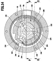
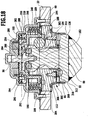
- an axially acting locking unit 180 designated as a whole as 180, is provided, which is in the Fig. 6 and 7th as well as 13 and 14 is shown.
- the axially acting locking unit 180 comprises a central receiving carrier 182 which can be moved along with the swivel element 80, preferably the swivel bearing body 82 in the axial direction to the swivel axis 50, which is preferably formed in one piece on the swivel bearing body 82 in the illustrated embodiment and preferably has a plurality of locking receptacles 184, which at This exemplary embodiment is formed, for example, by a circumferential recess 186 in the pivot bearing body 82, which lies between the outer bearing section 86 and the inner bearing section 96, but individual locking receptacles 184 can also be provided in the central receiving carrier.
- Each locking receptacle 184 has, for its part, a locking surface 188 which extends obliquely, preferably conically, to the pivot axis 50 and with increasing radial extent away from the pivot axis 50, to which a draw-in surface 189, which extends with the same or a varying inclination to the pivot axis 50, adjoins which is radially extends beyond the bearing section 86.
- the draw-in surface 189 is arranged at least partially or entirely, for example, on an annular body 190 placed on the pivot bearing body 82 and protruding radially beyond the pivot bearing body.
- the receiving carrier 182 in such a way that it has the draw-in surface 189 over its entire radial extent.
- locking elements 194 together, which are movable in a radial direction RA to the pivot axis 50 in a guide carrier 200 connected to the pivot bearing base 60, namely in guides 202 of the same, so that they move with at least one component in the radial direction RA can, and are also movable in a surface 204 which runs transversely to the pivot axis 50 and preferably represents a plane perpendicular to the pivot axis 50.
- the surface 204 could, however, theoretically also be designed as a surface which runs at least slightly conical to the pivot axis 50.
- the guides 202 are preferably designed as groove-like depressions, which lie between ribs 206 extending from the guide carrier 200 in the direction of the housing body 100, the ribs 206 forming the respective side surfaces 208 of the guides 202, between which the locking elements 194 in the radial direction RA are guided, and the guide support 200 also forms a guide base 210 on which the locking elements 194 are supported and against a movement in the direction of the pivot axis 50 on the guide support 200, which defines the shape of the surface 204 along which the locking elements 194 can be moved their locking receptacles 184 to engage or disengage.
- an actuating element designated as a whole with 220 which has an actuating surface carrier 222 which encloses all of the locking elements 194 on their radially outer side opposite the locking receptacles 184 and for each of the locking elements 194 has an actuating surface sequence 224 extending in a direction of rotation 226, which is defined by a radially outer release surface area 232 which, as in FIG Fig.
- a clamping surface area 236, which also has a radial distance from the pivot axis 50 that decreases with increasing extension in the direction of rotation 226 and serves to keep the locking elements 194 in the locking position constant or varying , for example increasing force to move in the direction of the locking receptacle 184 provided for this until an end surface area 238 of the actuating surface sequence 224 is reached, in which the respective locking element 194 acts on the locking receptacles 184 that in the locking position a bracing of the receptacle carrier 182 relative to the Guide carrier 200 and due to the form-fit element carrier 112 formed in one piece with the guide carrier 200, the toothed segments 114, 118, 124, 128, 134, 144 of the form-fit element carriers 112 and 132 are braced.
- the actuating element 220 is annular in the area of the actuating surface carrier 222 and is rotatably mounted in the housing body 100 about the pivot axis 50, so that the surface areas 232, 234, 236 and 238 also extend around the pivot axis 50 via arc segments that follow one another in the direction of rotation 226 and by rotating the actuating element 220 about the pivot axis 50, different different surface areas 232 to 238 act on the locking elements 194 in order to move them in the radial direction RA to the pivot axis 50 in the guides 202.
- the actuating element 220 In order to ensure that in the manually non-actuated state of the trailer coupling according to the invention, for example, the actuating element 220 always acts on the locking elements 194 in such a way that they have the tendency to move in the direction of the locking receptacles 184 and to generate the force F acting on the pivot element 80 Actuating element 220 acted upon by a torsion spring 240 in the direction of a direction of rotation 242 in the sense of a movement from the release position into the locking position or clamping position, so that the actuating element 220 always endeavors to act upon the locking elements 194 in the direction of the locking position or the clamping position, so that the locking elements 194 thereby act due to the action of the torsion spring 240 in the unactuated position of the actuating element 220 in the pivoting position on the retraction surfaces 189 and / or in the fixing position on the locking surfaces 188 and thereby the receiving carrier he 182 with the force F, so that this consequently has the tendency
- the torsion spring 240 is preferably designed so that it wraps around the actuating surface support 222 of the actuating element 220 and engages with one end 244 on the actuation surface support 222 of the actuation element 220, while it engages with the other end 246 on the pivot bearing base 60 and thus with this end 246 relatively is fixed to the pivot bearing base 40.
- a rotary drive element designated as a whole by 250 is provided which, as in FIG Fig. 15 and 16 shown, also extends annularly around the pivot axis 50 and can be coupled to the actuating element 220 via a free-motion coupling 252.
- the actuating element 220 as in Fig. 6 and 7th shown, provided with a cam 256 on an inner part 254 connected to the actuating surface carrier 222 and arranged on the side of the actuating surface carrier 222 facing away from the pivot bearing base, which can be acted upon by a driver 258 of the rotary drive element 250 projecting in the direction of the cam 256, in order to move the cam 256 and thus also being able to rotate the actuating element 220 with the rotary driving element 250.
- the rotary movement of the rotary driving element 250 can be, for example, as shown in Fig. 15 and 16 shown, triggered by a pull rope 262 acting on the rotary driver element 250.
- the rotary driving element 250 is in its in.
- a torsion spring 264 Fig. 15 The starting position shown can be brought, while pulling on the pull rope 262 causes the rotary driver element 250 to rotate counter to the force of the torsion spring 264 in the direction of rotation 260 in order to then take the cam 256 with it from a driver position with the driver 258 and thus to rotate the actuating element 220.
- the free-range clutch 252 serves to unlock a securing unit 270, the securing unit 270 serving to prevent the actuating element 220 from rotating out of the locked position.
- the securing unit 270 comprises a securing element 272, which is mounted displaceably parallel to the pivot axis 50 in the actuating element 220, preferably the actuating surface carrier 222, and can be brought into engagement with a securing receptacle 274 in the swivel bearing base 60 and then engages when the actuating element 220 is rotated from one of the possible locking positions, including the clamping positions, in which the release position is to be prevented.
- the securing element 272 is preferably acted upon in one direction by a spring 276 such that it is automatically released from the securing receptacle when the movement of the securing element 272 is released.
- the action of the securing element 272 in the direction of the securing receptacle 274 and the immersion in the securing receptacle 274 is brought about by a slide track 278 on the rotary drive element 250, the slide track 278 connecting the securing element 272 with the securing receptacle 274 preferably shortly before the actuating element is taken along by the Can cam 256 acting driver 258 come out of engagement to allow rotation of the actuating element 220.
- the actuating element 220 has also reached its locking position or tensioning position due to the action of the torsion spring 240, so that the securing element 272 through the slide track 278 with the securing receptacle 274 in Has been brought into engagement and is held in engagement by the slide track 278.
- the securing unit 270 thus additionally secures the actuating element against automatic loosening.
- the pivot element 80 in particular the pivot bearing body 82, also moves against the direction of the force F in the direction of the pivot axis 50, as in FIG Fig.
- a push-out unit 280 which has a push-out element 282, which is provided on the inner part 254 of the actuating element 220 and has an inclined surface 284, which has a region 286 at a maximum distance from the pivot bearing base 60 and rises up to a region 288 with minimal distance from the pivot bearing base 60, so that when the actuating element 220 is rotated, the inclined surface 284 of the push-out element 282 acts on a pressure receiving element 290, which is designed, for example, as a ball and, for example, in a stepped transition area 292 of the pivot bearing body 82 from the area forming the receiving carrier 182 the inner bearing section 96 is arranged and guided into a cage body 294 connected to the ring body 190 and held by this on the pivot bearing body 82
- the push-out element 282 with the inclined surface 284 is arranged in such a way that it acts on the pressure-receiving element 290, which is arranged on the pivot element 80, when the actuating element 220 has already been rotated in the direction of rotation 260 to such an extent that it releases the locking elements 194 and in lets pass the release position.
- the push-out element 282 then becomes effective with the inclined surface 284 and acts on the pressure-receiving element 290 in such a way that when the actuating element 220 is rotated further, the swivel element 80 and also the swivel bearing body 82 move from the fixing position into the swivel position by moving in the direction of the swivel axis 50.
- a sealing unit 300 is provided on the pivot bearing body 60, for example radially outside the form-fit element carrier 112, which is arranged circumferentially around it and which is fixed with a fastening segment 302 in a groove 304 in the pivot bearing base 60 and with a cylindrical Shielding segment 306 extending from the fastening segment 302 in the direction of the swivel bearing body head 130 and with an end segment 308, which bears ribs 310 protruding radially inward and circumferentially around the swivel axis 50, and with this on a cylindrical circumferential surface 312 of the swivel bearing body head 130 that runs towards the swivel axis 50 when the pivot element 80 is moved between the fixing position and the pivot position, the cylindrical circumferential surface 312 is movable relative to the end segment 308 and the ribs 310, the end segment 308 with de
- n ribs 310 are arranged
- end segment 308 with the ribs 310 is undersized with respect to the cylindrical circumferential surface 312 so that the end segment with the ribs 310 rests against the cylindrical circumferential surface 312 with force in the radial direction and provides the required sealing effect.
- the driver 258 After passing through the angular distance W, the driver 258 reaches the cam 256 and acts on the actuating element 220 in such a way that it is rotated in the direction of rotation 260 against the action of the torsion spring 240 from the locking position, in particular the clamping position in the locking position, in the direction of its release position .
- the locking elements 194 are given the opportunity to move from the locking position, in particular the clamping position in the locking position, in the direction of their release position, as has already been described.
- the push-out unit 280 becomes effective in the manner described and moves the pivot element 80 from the fixing position into the pivot position in the described way.
- the track follower 162 disengages from the recess 166, 168 of the fixing blocking unit 160 assigned to the initial position.
- the form-fit elements 114, 118, 124, 128, 134, 144 no longer engage with one another, but allow free rotation about the pivot axis, so that after the pivoted position has been reached, the pivot element 80 with the ball neck 40 moves from the starting position, for example the Working position or the rest position, into the respective end position, for example the rest position or the working position, can pivot about the pivot axis 50, immediately after the pivoting element 80 begins to pivot about the pivot axis 50, the path follower 162 no longer faces one of the depressions 166 and 168 , but the guide track 164 faces.
- the rotary drive element 250 moves opposite to the direction of rotation 260 in the direction of its starting position and consequently the actuation element 220 is subjected to the force of the torsion spring 240, which is the aim to move the actuating element 220 from the release position into the locking position and in particular into the clamping position of the same.
- the guide track 164 acts with the force F against the track follower 162, but the track follower 162 prevents the pivot element 80 from moving from the pivot position into the fixing position.
- Rotation of the pivot element 80 and thus also of the ball neck 40 is thus possible until it has reached the respective end position in which the track follower 162 again faces one of the depressions 168 or 166.
- the pivoting element 80 can move from the pivoting position into the fixing position, this taking place under the action of the force F generated by the locking elements 194 in cooperation with the draw-in surface 189, which is still present when the locking elements reach the locking surfaces 188 of the receiving carrier 182 act.
- the locking elements 194 When the receiving carrier 182 is moved from the pivoting position to the fixing position, the locking elements 194 also move from their release position into the locking position, in particular even the clamping position, under the action of the actuation surface sequence 224 in the manner described, so that the actuation element 220 is also able to do so to move into the locking position, in particular into the clamping position of the locking position, so that again the cam 256 is at an angular distance W from the driver 258 of the rotary driver element 250, so that again the initial state is present from which the function of the trailer coupling according to the invention is described has been.
- the securing unit 270 becomes effective again through the engagement of the securing element 272 with the securing receptacle 274, the securing element 272 being acted upon by the torsion spring 264 against the force of the spring 276 in FIG the fuse holder 274 is moved in.
- FIG Figures 19 and 20 In a second embodiment of the trailer coupling according to the invention, shown in FIG Figures 19 and 20 , all those elements which are identical to those of the exemplary embodiment described above are provided with the same reference numerals, so that reference can be made to the full content of the explanations relating to this.
- the rotary driving element 250 cannot be driven by a cable, but is provided with external toothing 320 which, for example, runs conically to the pivot axis 50.
- a drive pinion 322 which can be driven by an actuating motor 324, which preferably also has an integrated reduction gear, is in engagement with this external toothing 320.
- a drive wheel 330 is provided between the inner bearing section 96, which carries the inner guide surface 98, and the receiving carrier 182 of the locking unit 180, which is connected non-rotatably to the pivot bearing body 82, the drive wheel 330 being designed as a bevel gear, for example.
- Both the swivel motor 334 and the actuating motor 324 can be controlled by a controller designated as a whole by 340, which controls the actuating motor 324 and the swivel motor 334 as follows.
- the control 340 first actuates the actuating motor 324 so that it moves the rotary driver element 250 from the starting position into the driving position moved and then rotated the actuating element 220 in the driving position so that it passes from its clamping position or locking position into the release position and thus releases the locking of the receiving carrier 182 on the part of the locking unit 180.
- the actuation element 220 is rotated further by the actuation motor 324 until the pushing-out unit 280 moves the swivel element 80 from the fixing position into the swivel position, for example shown in FIG Fig. 7 , has moved.
- the pivoting motor 334 is activated, which causes pivoting from the working position into the rest position or from the rest position into the working position.
- the actuating motor 324 can be operated in the opposite direction, so that the rotary drive element 250 is again driven into the starting position by the actuating motor 324.
- the torsion spring 240 acts on it and consequently the actuation element 220 acts on the locking elements 194 in FIG Direction of the locking position, so that they generate the force F on the pivot element 80 by acting on the draw-in surface 189.
- the force F does not lead to a movement in the direction of the fixing position until the respective end position is reached, that is to say the working position or the rest position, since this is prevented by the interaction of the track follower 162 with the guide track 184.
- the receiving carrier 182 and thus the pivoting element 80 are moved in the direction of the fixing position, since the locking elements 194 are acted upon by the actuation element 220, in particular the actuation surface sequence 224, and triggered by the torsion spring 240 generate the force F and the transition to the fixing position is possible in that the track follower 162 can enter the recesses 166 and 168 in the respective end position and thus allows the pivoting element 80 to be moved from the pivoting position into the fixing position.
- control 340 switches off the swivel motor 334 each time the end position is reached.
Landscapes
- Engineering & Computer Science (AREA)
- Transportation (AREA)
- Mechanical Engineering (AREA)
- Pivots And Pivotal Connections (AREA)
- Mechanical Operated Clutches (AREA)
- Vehicle Cleaning, Maintenance, Repair, Refitting, And Outriggers (AREA)
- Mutual Connection Of Rods And Tubes (AREA)
Claims (16)
- Attelage de remorque comprenant une unité de maintien (26) pouvant être fixement raccordée à une carrosserie de véhicule (12),
une unité de palier pivotant (30) prévue contre l'unité de maintien (26), avec une base (60) de palier pivotant fixement raccordée à l'unité de maintien (26) et avec un élément pivotant (80) pouvant pivoter par rapport à la base (60) de palier pivotant autour d'un axe de pivotement (50) entre une position de travail (A) et une position de repos (R) et pouvant coulisser dans la direction de l'axe de pivotement (50),
un col (40) de boule d'attelage, qui est maintenu par une extrémité (42) contre l'élément pivotant (80), qui porte une boule d'attelage (46) à une autre extrémité (44) et qui peut pivoter, du fait de l'aptitude au pivotement de l'élément pivotant (80) autour de l'axe de pivotement (50), entre la position de travail (A) et la position de repos (R), dans lequel le col (40) de boule d'attelage peut coulisser, du fait de l'aptitude au coulissement de l'élément pivotant (80), entre une position de fixation et la position de pivotement, dans lequel une unité de fixation (110) est prévue, laquelle fixe, en position de fixation de l'élément pivotant (80), l'élément pivotant (80) et par conséquent également le col (40) de boule d'attelage avec des éléments à engagement par complémentarité de forme (114, 118, 124, 128, 134, 144) enclenchables par le coulissement dans la direction de l'axe de pivotement (50), solidairement en rotation par rapport à la base (60) de palier pivotant, et permet un pivotement en position de pivotement, dans lequel une unité de verrouillage (180) est prévue, agissant axialement contre un déplacement dans la direction de l'axe de pivotement (50), et au moyen de laquelle l'unité de fixation (110) peut être fixée en position de fixation contre un déplacement vers la position de pivotement, dans lequel l'unité de verrouillage (180) agissant axialement comporte un corps de logement central (182) raccordé à l'élément pivotant (80) de manière non déplaçable dans la direction de l'axe de pivotement (50) et mobile avec l'élément pivotant (80) dans la direction de l'axe de pivotement (50), avec au moins un logement de verrouillage (184) radialement extérieur par rapport à l'axe de pivotement (50), dans lequel l'unité de verrouillage (180) comporte au moins un élément de verrouillage (194), qui est disposé dans un espace (192) autour du corps de logement (182) et qui peut être mis dans une position de verrouillage agissant sur le logement de verrouillage (184) pour le maintien de celui-ci en position de fixation, dans lequel l'unité de verrouillage (180) comporte un support de guidage (200) raccordé à la base (60) de palier pivotant avec au moins un guidage (202) pour ledit au moins un élément de verrouillage (194), le guidage (202) prescrivant audit au moins un élément de verrouillage (194) une direction de déplacement (RA) pour un déplacement entre la position de verrouillage et une position de desserrage par celui-ci, dans lequel l'unité de verrouillage (180) comporte un élément d'actionnement (220) agissant sur ledit au moins un élément de verrouillage (194) depuis un côté en face du corps de logement (182), dans lequel l'élément d'actionnement (220) permet de générer un déplacement de l'élément de verrouillage (194) de la position de desserrage vers la position de verrouillage ou de débloquer un déplacement de l'élément de verrouillage (194) de la position de verrouillage vers la position de desserrage,
caractérisé en ce que le logement de verrouillage (184) est doté d'une surface de rentrage (189) sur laquelle l'élément de verrouillage (194) peut agir avant d'atteindre la position de verrouillage pour rentrer le corps de logement (182) et ce faisant l'élément pivotant (80) dans la position de fixation, et en ce que la surface de rentrage (189) s'étend suffisamment loin pour que l'élément de verrouillage (194) puisse agir sur celle-ci dans la position de desserrage quand dans la position de desserrage se produit une sollicitation de l'élément de verrouillage (194) dans la direction de la position de verrouillage, de sorte qu'avec l'élément de verrouillage (194) un rentrage du corps de logement (182) soit déjà possible depuis la position de pivotement et qu'il soit également possible déjà dans la position de pivotement de laisser agir une force de rentrage sur le corps de logement (182). - Attelage de remorque selon la revendication 1, caractérisé en ce que le corps de logement central (182) comporte au moins deux logements de verrouillage (184), en ce qu'au moins deux éléments de verrouillage (194) sont disposés dans l'espace (192) autour du corps de logement central (182) et en ce que le support de guidage (200) comporte au moins deux guidages (202) pour lesdits au moins deux éléments de verrouillage (194).
- Attelage de remorque selon la revendication 1 ou 2, caractérisé en ce que l'élément d'actionnement (220) est rotatif autour de l'axe de pivotement (50) et comporte au moins une suite de surfaces d'actionnement (224) qui comprend une zone de surface la plus radialement extérieure et une zone de surface la plus radialement intérieure (232, 238), et en ce que ledit au moins un élément de verrouillage (194) est dans sa position de desserrage quand il est appliqué contre la zone de surface la plus radialement extérieure (232) et est dans sa position de verrouillage quand il est appliqué contre la zone de surface la plus radialement intérieure (238).
- Attelage de remorque selon l'une des revendications 1 à 3, caractérisé en ce que l'élément d'actionnement (220) entoure de manière radialement extérieure le corps de logement (182) et lesdits au moins deux éléments de verrouillage (194), et en ce que l'élément d'actionnement (220) comporte notamment un support de surface d'actionnement (222) de forme annulaire, sur lequel ladite au moins une suite de surfaces d'actionnement (224) est disposée.
- Attelage de remorque selon l'une des revendications précédentes, caractérisé en ce que l'élément d'actionnement (220) est constamment sollicité par un accumulateur d'énergie à ressort (240) dans la direction de sa position de verrouillage.
- Attelage de remorque selon l'une des revendications précédentes, caractérisé en ce qu'un déplacement de l'élément d'actionnement (220) de sa position de verrouillage vers sa position de desserrage peut être empêché par une unité de blocage (270).
- Attelage de remorque selon l'une des revendications précédentes, caractérisé en ce que l'élément d'actionnement (220) est actionnable par l'intermédiaire d'un élément d'entraînement rotatif (250) mobile depuis une position initiale vers une position d'entraînement.
- Attelage de remorque selon l'une des revendications précédentes, caractérisé en ce que l'unité de verrouillage (180) agissant axialement comporte une unité de poussée (280) agissant axialement.
- Attelage de remorque selon la revendication 8, caractérisé en ce que l'unité de poussée (280) comporte un élément de poussée (282) agissant dans la direction de l'axe de pivotement (50), au moyen duquel l'élément pivotant (80) est déplaçable de la position de fixation vers la position de pivotement.
- Attelage de remorque selon la revendication 9, caractérisé en ce que l'élément de poussée (282) agit sur un élément d'absorption de pression (290) accouplé à l'élément pivotant (80) et en ce que notamment l'élément de poussée (282) avec l'élément d'absorption de pression (290) déplace ensuite l'élément pivotant (80) de la position de fixation vers la position de pivotement quand ledit au moins un élément de verrouillage (194) peut atteindre sa position de desserrage.
- Attelage de remorque selon l'une des revendications précédentes, caractérisé en ce que ledit au moins un élément de verrouillage (194) s'appuie contre le guidage (202) en position de verrouillage.
- Attelage de remorque selon l'une des revendications précédentes, caractérisé en ce que le support de guidage (200) et un support fixe (112) d'élément à engagement par complémentarité de forme de l'unité de fixation (110) sont raccordés l'un à l'autre et en ce que notamment le support de guidage (200) et le support (112) d'élément à engagement par complémentarité de forme forment une pièce d'un seul tenant.
- Attelage de remorque selon la revendication 12, caractérisé en ce que le guidage (202) est disposé sur un côté en face des éléments à engagement par complémentarité de forme (114, 118, 124, 128) du support fixe (112) d'élément à engagement par complémentarité de forme.
- Attelage de remorque selon l'une des revendications précédentes, caractérisé en ce que l'élément pivotant (80) comporte un corps (82) de palier pivotant central, lequel est monté de manière pivotante autour de l'axe de pivotement (50) dans un logement (66) de corps de palier pivotant, entourant de manière radialement extérieure celui-ci, de la base (60) de palier pivotant, et de manière coulissante dans la direction de l'axe de pivotement (50) entre la position de pivotement et la position de fixation, et en ce que notamment le corps (82) de palier pivotant supporte un corps de logement central (182) de l'unité de verrouillage (180) agissant axialement, lequel présente au moins un logement de verrouillage (184) et est raccordé au corps (82) de palier pivotant de manière non déplaçable dans la direction de l'axe de pivotement (50).
- Attelage de remorque selon la revendication 14, caractérisé en ce que dans un espace (192) tout autour du corps de logement (182) est disposé au moins un élément de verrouillage (194) de l'unité de verrouillage (180) agissant axialement, lequel est guidé dans un guidage (202) d'un support de guidage (200) s'appuyant contre la base (60) de palier pivotant et peut être enclenché avec ledit au moins un logement de verrouillage (184) ou désenclenché de celui-ci par un élément d'actionnement (220) disposé sur un côté de l'élément de verrouillage (194) éloigné du corps de logement central (182).
- Attelage de remorque selon la revendication 14 ou la revendication 15, caractérisé en ce qu'un support fixe (112) d'élément à engagement par complémentarité de forme de l'unité de fixation (110) est disposé de manière radialement extérieure dans une zone de la base (60) de palier pivotant qui s'étend tout autour du corps (82) de palier pivotant.
Applications Claiming Priority (1)
| Application Number | Priority Date | Filing Date | Title |
|---|---|---|---|
| DE102011053506A DE102011053506A1 (de) | 2011-09-12 | 2011-09-12 | Anhängekupplung |
Publications (3)
| Publication Number | Publication Date |
|---|---|
| EP2567836A1 EP2567836A1 (fr) | 2013-03-13 |
| EP2567836B1 EP2567836B1 (fr) | 2016-04-06 |
| EP2567836B2 true EP2567836B2 (fr) | 2021-04-21 |
Family
ID=46826330
Family Applications (2)
| Application Number | Title | Priority Date | Filing Date |
|---|---|---|---|
| EP12183766.0A Active EP2567836B2 (fr) | 2011-09-12 | 2012-09-10 | Attelage |
| EP12183764.5A Active EP2567835B2 (fr) | 2011-09-12 | 2012-09-10 | Attelage |
Family Applications After (1)
| Application Number | Title | Priority Date | Filing Date |
|---|---|---|---|
| EP12183764.5A Active EP2567835B2 (fr) | 2011-09-12 | 2012-09-10 | Attelage |
Country Status (4)
| Country | Link |
|---|---|
| US (1) | US8967653B2 (fr) |
| EP (2) | EP2567836B2 (fr) |
| CN (1) | CN102991290B (fr) |
| DE (1) | DE102011053506A1 (fr) |
Families Citing this family (16)
| Publication number | Priority date | Publication date | Assignee | Title |
|---|---|---|---|---|
| DE102014109134A1 (de) * | 2014-06-30 | 2015-12-31 | Scambia Holdings Cyprus Limited | Anhängekupplung und Lastenträgereinrichtung für eine Anhängekupplung |
| DE102013007111A1 (de) * | 2013-04-21 | 2014-10-23 | Westfalia-Automotive Gmbh | Anhängekupplung |
| DE102014108071A1 (de) * | 2014-06-06 | 2015-12-17 | Scambia Holdings Cyprus Limited | Anhängekupplung |
| DE102014111426A1 (de) * | 2014-08-11 | 2016-02-11 | Scambia Holdings Cyprus Limited | Anhängekupplung |
| DE102015100490A1 (de) * | 2015-01-14 | 2016-07-14 | Scambia Holdings Cyprus Limited | Anhängekupplung |
| DE102015109411B4 (de) * | 2015-06-12 | 2017-02-16 | Ercan Mutlu | Anhängerkupplung für ein Kraftfahrzeug |
| DE102016117017A1 (de) * | 2016-09-09 | 2018-03-15 | Westfalia-Automotive Gmbh | Anhängekupplung mit einem Kupplungsarm |
| CZ308583B6 (cs) | 2017-01-20 | 2020-12-16 | Vapos, Spol. S R.O. | Automatické výklopné tažné zařízení především pro osobní automobil |
| DE102017102505A1 (de) | 2017-02-08 | 2018-08-09 | Bosal Acps Holding 2 B.V. | Anhängekupplung |
| DE102017102504A1 (de) | 2017-02-08 | 2018-08-09 | Bosal Acps Holding 2 B.V. | Anhängekupplung |
| DE112020004480A5 (de) * | 2019-11-29 | 2022-06-15 | Westfalia-Automotive Gmbh | Anhängekupplung mit einem schwenkbaren Kupplungsarm |
| DE102020134914A1 (de) * | 2020-11-03 | 2022-05-05 | Westfalia-Automotive Gmbh | Anhängekupplung mit einer Bremseinrichtung |
| CN116872656B (zh) * | 2023-07-14 | 2025-08-26 | 浙江致优汽车科技有限公司 | 拖车联接器 |
| DE202024002589U1 (de) | 2024-12-03 | 2026-04-09 | Brose Fahrzeugteile SE & Co. Kommanditgesellschaft, Coburg | Anhängerkupplung für ein Fahrzeug mit ein schwenkbares Verriegelungselement aufweisender Verriegelungseinrichtung |
| DE202024107509U1 (de) | 2024-12-03 | 2026-04-09 | Brose Fahrzeugteile SE & Co. Kommanditgesellschaft, Coburg | Anhängerkupplung für ein Fahrzeug mit axial verstellbarer Sperrkomponente einer Verriegelungseinrichtung |
| DE202024107508U1 (de) | 2024-12-03 | 2026-04-09 | Brose Fahrzeugteile SE & Co. Kommanditgesellschaft, Coburg | Anhängerkupplung für ein Fahrzeug mit zweistufiger Verriegelungseinrichtung |
Citations (8)
| Publication number | Priority date | Publication date | Assignee | Title |
|---|---|---|---|---|
| DE6936956U (de) † | 1969-09-19 | 1970-01-15 | Westfalia Werke Knoebel | Kugelstange fuer kupplungskugel mit halterung |
| US5277448A (en) † | 1993-05-10 | 1994-01-11 | Colibert Floyd A | Concealed vertical hitch receiver |
| DE19902355A1 (de) † | 1999-01-21 | 2000-08-03 | Oris Fahrzeugteile Riehle H | Anhängekupplung |
| EP1288026B1 (fr) † | 2001-09-03 | 2005-04-27 | ORIS FAHRZEUGTEILE HANS RIEHLE GmbH | Attelage de remorque |
| DE102004004503A1 (de) † | 2004-01-22 | 2005-08-18 | Oris Fahrzeugteile Hans Riehle Gmbh | Anhängekupplung |
| EP1504928B1 (fr) † | 2003-08-08 | 2006-02-22 | Westfalia Automotive GmbH & Co. KG | Attache remorque |
| US20100270774A1 (en) † | 2009-04-28 | 2010-10-28 | Midway Products Group, Inc. | Rotatable Trailer Hitch |
| DE102009033911A1 (de) † | 2009-07-20 | 2011-01-27 | Westfalia-Automotive Gmbh | Anhängekupplung |
Family Cites Families (16)
| Publication number | Priority date | Publication date | Assignee | Title |
|---|---|---|---|---|
| DE19612961A1 (de) * | 1996-04-01 | 1997-10-02 | Oris Fahrzeugteile Riehle H | Anhängekupplung |
| DE19859961C2 (de) * | 1998-12-29 | 2003-07-03 | Westfalia Automotive Gmbh & Co | Anhängerkupplung mit einem schwenkbaren Kugelhals |
| DE10017013A1 (de) * | 2000-04-05 | 2001-10-18 | Oris Fahrzeugteile Riehle H | Anhängekupplung |
| DE50302195D1 (de) | 2002-02-28 | 2006-04-06 | Kober Ag | Schwenkbare anhängevorrichtung für zugfahrzeuge |
| DE10231221A1 (de) * | 2002-07-11 | 2004-01-29 | Dr.Ing.H.C. F. Porsche Ag | Anhängezugvorrichtung |
| DE10252722B3 (de) * | 2002-11-13 | 2004-02-19 | Westfalia-Automotive Gmbh & Co. Kg | Anhängekupplung für Kraftfahrzeuge |
| DE10320302A1 (de) | 2003-05-07 | 2004-12-09 | Westfalia-Automotive Gmbh & Co. Kg | Anhängekupplung für Kraftfahrzeuge |
| DE10329622A1 (de) * | 2003-06-26 | 2005-01-20 | Oris Fahrzeugteile Hans Riehle Gmbh | Anhängekupplung |
| DE10347817B4 (de) * | 2003-10-10 | 2014-07-10 | Westfalia-Automotive Gmbh | Anhängekupplung |
| DE102006008837A1 (de) | 2006-02-27 | 2007-09-06 | Westfalia-Automotive Gmbh | Anhängerkupplung für Kraftfahrzeuge |
| DE202006008463U1 (de) | 2006-05-24 | 2006-07-27 | Fac Gmbh | Anhängerkupplung |
| DE102006035261A1 (de) * | 2006-07-29 | 2008-01-31 | Scambia Industrial Developments Aktiengesellschaft | Anhängekupplung |
| EP1902871B2 (fr) * | 2006-09-18 | 2012-11-28 | WESTFALIA - Automotive GmbH | Attelage |
| DE102006044401A1 (de) | 2006-09-18 | 2008-03-27 | Bpw Fahrzeugtechnik Gmbh & Co. Kg | Zugdeichsel für Fahrzeuganhänger |
| DE102008035987A1 (de) * | 2008-08-01 | 2010-02-04 | Westfalia-Automotive Gmbh | Anhängekupplung |
| DE102008047547B4 (de) * | 2008-09-16 | 2014-04-03 | Westfalia-Automotive Gmbh | Anhängekupplung für Kraftfahrzeuge |
-
2011
- 2011-09-12 DE DE102011053506A patent/DE102011053506A1/de not_active Ceased
-
2012
- 2012-09-10 EP EP12183766.0A patent/EP2567836B2/fr active Active
- 2012-09-10 EP EP12183764.5A patent/EP2567835B2/fr active Active
- 2012-09-12 US US13/612,174 patent/US8967653B2/en active Active
- 2012-09-12 CN CN201210337149.XA patent/CN102991290B/zh active Active
Patent Citations (8)
| Publication number | Priority date | Publication date | Assignee | Title |
|---|---|---|---|---|
| DE6936956U (de) † | 1969-09-19 | 1970-01-15 | Westfalia Werke Knoebel | Kugelstange fuer kupplungskugel mit halterung |
| US5277448A (en) † | 1993-05-10 | 1994-01-11 | Colibert Floyd A | Concealed vertical hitch receiver |
| DE19902355A1 (de) † | 1999-01-21 | 2000-08-03 | Oris Fahrzeugteile Riehle H | Anhängekupplung |
| EP1288026B1 (fr) † | 2001-09-03 | 2005-04-27 | ORIS FAHRZEUGTEILE HANS RIEHLE GmbH | Attelage de remorque |
| EP1504928B1 (fr) † | 2003-08-08 | 2006-02-22 | Westfalia Automotive GmbH & Co. KG | Attache remorque |
| DE102004004503A1 (de) † | 2004-01-22 | 2005-08-18 | Oris Fahrzeugteile Hans Riehle Gmbh | Anhängekupplung |
| US20100270774A1 (en) † | 2009-04-28 | 2010-10-28 | Midway Products Group, Inc. | Rotatable Trailer Hitch |
| DE102009033911A1 (de) † | 2009-07-20 | 2011-01-27 | Westfalia-Automotive Gmbh | Anhängekupplung |
Also Published As
| Publication number | Publication date |
|---|---|
| DE102011053506A1 (de) | 2013-03-14 |
| US20130093162A1 (en) | 2013-04-18 |
| CN102991290B (zh) | 2016-12-21 |
| EP2567835B1 (fr) | 2016-08-10 |
| EP2567835A1 (fr) | 2013-03-13 |
| EP2567836B1 (fr) | 2016-04-06 |
| CN102991290A (zh) | 2013-03-27 |
| US8967653B2 (en) | 2015-03-03 |
| EP2567835B2 (fr) | 2021-03-17 |
| EP2567836A1 (fr) | 2013-03-13 |
Similar Documents
| Publication | Publication Date | Title |
|---|---|---|
| EP2567836B2 (fr) | Attelage | |
| EP1557298B1 (fr) | Attelage de remorque | |
| EP2141034B2 (fr) | Attelage | |
| EP1741572B2 (fr) | Attelage de remorque | |
| EP3774496B1 (fr) | Colonne de direction pour un véhicule automobile | |
| DE102014111426A1 (de) | Anhängekupplung | |
| EP2792514B1 (fr) | Attelage | |
| EP3577010B1 (fr) | Colonne de direction à positionnement motorisé pour véhicule automobile | |
| EP1475253A1 (fr) | Attelage de remorque pour véhicules automobiles | |
| EP4021739B1 (fr) | Attelage de remorque doté d'un dispositif de réglage | |
| EP3860868A2 (fr) | Attelage de remorque | |
| EP2792513B1 (fr) | Attelage | |
| EP1057696B1 (fr) | Dispositif à arceau de sécurité pour véhicules | |
| EP1197357A1 (fr) | Attelage de remorque | |
| EP2799261B1 (fr) | Attelage | |
| EP2796304B1 (fr) | Attelage | |
| EP2796303B1 (fr) | Attelage | |
| EP2796305B1 (fr) | Attelage | |
| DE10125781A1 (de) | Anhängevorrichtung |
Legal Events
| Date | Code | Title | Description |
|---|---|---|---|
| PUAI | Public reference made under article 153(3) epc to a published international application that has entered the european phase |
Free format text: ORIGINAL CODE: 0009012 |
|
| AK | Designated contracting states |
Kind code of ref document: A1 Designated state(s): AL AT BE BG CH CY CZ DE DK EE ES FI FR GB GR HR HU IE IS IT LI LT LU LV MC MK MT NL NO PL PT RO RS SE SI SK SM TR |
|
| AX | Request for extension of the european patent |
Extension state: BA ME |
|
| 17P | Request for examination filed |
Effective date: 20130911 |
|
| RBV | Designated contracting states (corrected) |
Designated state(s): AL AT BE BG CH CY CZ DE DK EE ES FI FR GB GR HR HU IE IS IT LI LT LU LV MC MK MT NL NO PL PT RO RS SE SI SK SM TR |
|
| GRAP | Despatch of communication of intention to grant a patent |
Free format text: ORIGINAL CODE: EPIDOSNIGR1 |
|
| INTG | Intention to grant announced |
Effective date: 20151002 |
|
| GRAS | Grant fee paid |
Free format text: ORIGINAL CODE: EPIDOSNIGR3 |
|
| GRAA | (expected) grant |
Free format text: ORIGINAL CODE: 0009210 |
|
| AK | Designated contracting states |
Kind code of ref document: B1 Designated state(s): AL AT BE BG CH CY CZ DE DK EE ES FI FR GB GR HR HU IE IS IT LI LT LU LV MC MK MT NL NO PL PT RO RS SE SI SK SM TR |
|
| REG | Reference to a national code |
Ref country code: GB Ref legal event code: FG4D Free format text: NOT ENGLISH |
|
| REG | Reference to a national code |
Ref country code: AT Ref legal event code: REF Ref document number: 787333 Country of ref document: AT Kind code of ref document: T Effective date: 20160415 Ref country code: CH Ref legal event code: EP |
|
| REG | Reference to a national code |
Ref country code: IE Ref legal event code: FG4D Free format text: LANGUAGE OF EP DOCUMENT: GERMAN |
|
| REG | Reference to a national code |
Ref country code: DE Ref legal event code: R096 Ref document number: 502012006568 Country of ref document: DE |
|
| REG | Reference to a national code |
Ref country code: NL Ref legal event code: FP |
|
| REG | Reference to a national code |
Ref country code: LT Ref legal event code: MG4D |
|
| REG | Reference to a national code |
Ref country code: FR Ref legal event code: PLFP Year of fee payment: 5 |
|
| PG25 | Lapsed in a contracting state [announced via postgrant information from national office to epo] |
Ref country code: FI Free format text: LAPSE BECAUSE OF FAILURE TO SUBMIT A TRANSLATION OF THE DESCRIPTION OR TO PAY THE FEE WITHIN THE PRESCRIBED TIME-LIMIT Effective date: 20160406 Ref country code: NO Free format text: LAPSE BECAUSE OF FAILURE TO SUBMIT A TRANSLATION OF THE DESCRIPTION OR TO PAY THE FEE WITHIN THE PRESCRIBED TIME-LIMIT Effective date: 20160706 Ref country code: IS Free format text: LAPSE BECAUSE OF FAILURE TO SUBMIT A TRANSLATION OF THE DESCRIPTION OR TO PAY THE FEE WITHIN THE PRESCRIBED TIME-LIMIT Effective date: 20160806 Ref country code: PL Free format text: LAPSE BECAUSE OF FAILURE TO SUBMIT A TRANSLATION OF THE DESCRIPTION OR TO PAY THE FEE WITHIN THE PRESCRIBED TIME-LIMIT Effective date: 20160406 Ref country code: LT Free format text: LAPSE BECAUSE OF FAILURE TO SUBMIT A TRANSLATION OF THE DESCRIPTION OR TO PAY THE FEE WITHIN THE PRESCRIBED TIME-LIMIT Effective date: 20160406 |
|
| PG25 | Lapsed in a contracting state [announced via postgrant information from national office to epo] |
Ref country code: HR Free format text: LAPSE BECAUSE OF FAILURE TO SUBMIT A TRANSLATION OF THE DESCRIPTION OR TO PAY THE FEE WITHIN THE PRESCRIBED TIME-LIMIT Effective date: 20160406 Ref country code: PT Free format text: LAPSE BECAUSE OF FAILURE TO SUBMIT A TRANSLATION OF THE DESCRIPTION OR TO PAY THE FEE WITHIN THE PRESCRIBED TIME-LIMIT Effective date: 20160808 Ref country code: LV Free format text: LAPSE BECAUSE OF FAILURE TO SUBMIT A TRANSLATION OF THE DESCRIPTION OR TO PAY THE FEE WITHIN THE PRESCRIBED TIME-LIMIT Effective date: 20160406 Ref country code: ES Free format text: LAPSE BECAUSE OF FAILURE TO SUBMIT A TRANSLATION OF THE DESCRIPTION OR TO PAY THE FEE WITHIN THE PRESCRIBED TIME-LIMIT Effective date: 20160406 Ref country code: GR Free format text: LAPSE BECAUSE OF FAILURE TO SUBMIT A TRANSLATION OF THE DESCRIPTION OR TO PAY THE FEE WITHIN THE PRESCRIBED TIME-LIMIT Effective date: 20160707 Ref country code: SE Free format text: LAPSE BECAUSE OF FAILURE TO SUBMIT A TRANSLATION OF THE DESCRIPTION OR TO PAY THE FEE WITHIN THE PRESCRIBED TIME-LIMIT Effective date: 20160406 Ref country code: RS Free format text: LAPSE BECAUSE OF FAILURE TO SUBMIT A TRANSLATION OF THE DESCRIPTION OR TO PAY THE FEE WITHIN THE PRESCRIBED TIME-LIMIT Effective date: 20160406 |
|
| PG25 | Lapsed in a contracting state [announced via postgrant information from national office to epo] |
Ref country code: IT Free format text: LAPSE BECAUSE OF FAILURE TO SUBMIT A TRANSLATION OF THE DESCRIPTION OR TO PAY THE FEE WITHIN THE PRESCRIBED TIME-LIMIT Effective date: 20160406 |
|
| REG | Reference to a national code |
Ref country code: DE Ref legal event code: R026 Ref document number: 502012006568 Country of ref document: DE |
|
| PLBI | Opposition filed |
Free format text: ORIGINAL CODE: 0009260 |
|
| PG25 | Lapsed in a contracting state [announced via postgrant information from national office to epo] |
Ref country code: SK Free format text: LAPSE BECAUSE OF FAILURE TO SUBMIT A TRANSLATION OF THE DESCRIPTION OR TO PAY THE FEE WITHIN THE PRESCRIBED TIME-LIMIT Effective date: 20160406 Ref country code: RO Free format text: LAPSE BECAUSE OF FAILURE TO SUBMIT A TRANSLATION OF THE DESCRIPTION OR TO PAY THE FEE WITHIN THE PRESCRIBED TIME-LIMIT Effective date: 20160406 Ref country code: CZ Free format text: LAPSE BECAUSE OF FAILURE TO SUBMIT A TRANSLATION OF THE DESCRIPTION OR TO PAY THE FEE WITHIN THE PRESCRIBED TIME-LIMIT Effective date: 20160406 Ref country code: DK Free format text: LAPSE BECAUSE OF FAILURE TO SUBMIT A TRANSLATION OF THE DESCRIPTION OR TO PAY THE FEE WITHIN THE PRESCRIBED TIME-LIMIT Effective date: 20160406 Ref country code: EE Free format text: LAPSE BECAUSE OF FAILURE TO SUBMIT A TRANSLATION OF THE DESCRIPTION OR TO PAY THE FEE WITHIN THE PRESCRIBED TIME-LIMIT Effective date: 20160406 |
|
| 26 | Opposition filed |
Opponent name: WESTFALIA - AUTOMOTIVE GMBH Effective date: 20170104 |
|
| PLAX | Notice of opposition and request to file observation + time limit sent |
Free format text: ORIGINAL CODE: EPIDOSNOBS2 |
|
| PG25 | Lapsed in a contracting state [announced via postgrant information from national office to epo] |
Ref country code: SM Free format text: LAPSE BECAUSE OF FAILURE TO SUBMIT A TRANSLATION OF THE DESCRIPTION OR TO PAY THE FEE WITHIN THE PRESCRIBED TIME-LIMIT Effective date: 20160406 Ref country code: BE Free format text: LAPSE BECAUSE OF NON-PAYMENT OF DUE FEES Effective date: 20160930 |
|
| PG25 | Lapsed in a contracting state [announced via postgrant information from national office to epo] |
Ref country code: MC Free format text: LAPSE BECAUSE OF FAILURE TO SUBMIT A TRANSLATION OF THE DESCRIPTION OR TO PAY THE FEE WITHIN THE PRESCRIBED TIME-LIMIT Effective date: 20160406 |
|
| REG | Reference to a national code |
Ref country code: CH Ref legal event code: PL |
|
| PLAF | Information modified related to communication of a notice of opposition and request to file observations + time limit |
Free format text: ORIGINAL CODE: EPIDOSCOBS2 |
|
| PG25 | Lapsed in a contracting state [announced via postgrant information from national office to epo] |
Ref country code: SI Free format text: LAPSE BECAUSE OF FAILURE TO SUBMIT A TRANSLATION OF THE DESCRIPTION OR TO PAY THE FEE WITHIN THE PRESCRIBED TIME-LIMIT Effective date: 20160406 |
|
| PLBB | Reply of patent proprietor to notice(s) of opposition received |
Free format text: ORIGINAL CODE: EPIDOSNOBS3 |
|
| REG | Reference to a national code |
Ref country code: IE Ref legal event code: MM4A |
|
| PG25 | Lapsed in a contracting state [announced via postgrant information from national office to epo] |
Ref country code: IE Free format text: LAPSE BECAUSE OF NON-PAYMENT OF DUE FEES Effective date: 20160910 Ref country code: LI Free format text: LAPSE BECAUSE OF NON-PAYMENT OF DUE FEES Effective date: 20160930 Ref country code: CH Free format text: LAPSE BECAUSE OF NON-PAYMENT OF DUE FEES Effective date: 20160930 |
|
| PG25 | Lapsed in a contracting state [announced via postgrant information from national office to epo] |
Ref country code: LU Free format text: LAPSE BECAUSE OF NON-PAYMENT OF DUE FEES Effective date: 20160910 |
|
| REG | Reference to a national code |
Ref country code: FR Ref legal event code: PLFP Year of fee payment: 6 |
|
| REG | Reference to a national code |
Ref country code: BE Ref legal event code: MM Effective date: 20160930 |
|
| REG | Reference to a national code |
Ref country code: DE Ref legal event code: R081 Ref document number: 502012006568 Country of ref document: DE Owner name: ACPS AUTOMOTIVE GMBH, DE Free format text: FORMER OWNER: SCAMBIA HOLDINGS CYPRUS LIMITED, LIMASSOL, CY Ref country code: DE Ref legal event code: R082 Ref document number: 502012006568 Country of ref document: DE Representative=s name: HOEGER, STELLRECHT & PARTNER PATENTANWAELTE MB, DE Ref country code: DE Ref legal event code: R081 Ref document number: 502012006568 Country of ref document: DE Owner name: BOSAL ACPS HOLDING 2 B.V., NL Free format text: FORMER OWNER: SCAMBIA HOLDINGS CYPRUS LIMITED, LIMASSOL, CY |
|
| RAP2 | Party data changed (patent owner data changed or rights of a patent transferred) |
Owner name: BOSAL ACPS HOLDING 2 B.V. |
|
| PG25 | Lapsed in a contracting state [announced via postgrant information from national office to epo] |
Ref country code: HU Free format text: LAPSE BECAUSE OF FAILURE TO SUBMIT A TRANSLATION OF THE DESCRIPTION OR TO PAY THE FEE WITHIN THE PRESCRIBED TIME-LIMIT; INVALID AB INITIO Effective date: 20120910 Ref country code: CY Free format text: LAPSE BECAUSE OF FAILURE TO SUBMIT A TRANSLATION OF THE DESCRIPTION OR TO PAY THE FEE WITHIN THE PRESCRIBED TIME-LIMIT Effective date: 20160406 |
|
| APBM | Appeal reference recorded |
Free format text: ORIGINAL CODE: EPIDOSNREFNO |
|
| APBP | Date of receipt of notice of appeal recorded |
Free format text: ORIGINAL CODE: EPIDOSNNOA2O |
|
| APAH | Appeal reference modified |
Free format text: ORIGINAL CODE: EPIDOSCREFNO |
|
| APAW | Appeal reference deleted |
Free format text: ORIGINAL CODE: EPIDOSDREFNO |
|
| PG25 | Lapsed in a contracting state [announced via postgrant information from national office to epo] |
Ref country code: MK Free format text: LAPSE BECAUSE OF FAILURE TO SUBMIT A TRANSLATION OF THE DESCRIPTION OR TO PAY THE FEE WITHIN THE PRESCRIBED TIME-LIMIT Effective date: 20160406 Ref country code: TR Free format text: LAPSE BECAUSE OF FAILURE TO SUBMIT A TRANSLATION OF THE DESCRIPTION OR TO PAY THE FEE WITHIN THE PRESCRIBED TIME-LIMIT Effective date: 20160406 Ref country code: MT Free format text: LAPSE BECAUSE OF FAILURE TO SUBMIT A TRANSLATION OF THE DESCRIPTION OR TO PAY THE FEE WITHIN THE PRESCRIBED TIME-LIMIT Effective date: 20160406 |
|
| PG25 | Lapsed in a contracting state [announced via postgrant information from national office to epo] |
Ref country code: BG Free format text: LAPSE BECAUSE OF FAILURE TO SUBMIT A TRANSLATION OF THE DESCRIPTION OR TO PAY THE FEE WITHIN THE PRESCRIBED TIME-LIMIT Effective date: 20160406 |
|
| APBQ | Date of receipt of statement of grounds of appeal recorded |
Free format text: ORIGINAL CODE: EPIDOSNNOA3O |
|
| REG | Reference to a national code |
Ref country code: GB Ref legal event code: 732E Free format text: REGISTERED BETWEEN 20180719 AND 20180725 |
|
| APBQ | Date of receipt of statement of grounds of appeal recorded |
Free format text: ORIGINAL CODE: EPIDOSNNOA3O |
|
| REG | Reference to a national code |
Ref country code: NL Ref legal event code: PD Owner name: BOSAL ACPS HOLDING 2 B.V.; NL Free format text: DETAILS ASSIGNMENT: CHANGE OF OWNER(S), ASSIGNMENT; FORMER OWNER NAME: SCAMBIA HOLDINGS CYPRUS LIMITED Effective date: 20180710 |
|
| REG | Reference to a national code |
Ref country code: FR Ref legal event code: PLFP Year of fee payment: 7 |
|
| PG25 | Lapsed in a contracting state [announced via postgrant information from national office to epo] |
Ref country code: AL Free format text: LAPSE BECAUSE OF FAILURE TO SUBMIT A TRANSLATION OF THE DESCRIPTION OR TO PAY THE FEE WITHIN THE PRESCRIBED TIME-LIMIT Effective date: 20160406 |
|
| REG | Reference to a national code |
Ref country code: AT Ref legal event code: MM01 Ref document number: 787333 Country of ref document: AT Kind code of ref document: T Effective date: 20170910 |
|
| PG25 | Lapsed in a contracting state [announced via postgrant information from national office to epo] |
Ref country code: AT Free format text: LAPSE BECAUSE OF NON-PAYMENT OF DUE FEES Effective date: 20170910 |
|
| REG | Reference to a national code |
Ref country code: DE Ref legal event code: R082 Ref document number: 502012006568 Country of ref document: DE Representative=s name: HOEGER, STELLRECHT & PARTNER PATENTANWAELTE MB, DE Ref country code: DE Ref legal event code: R081 Ref document number: 502012006568 Country of ref document: DE Owner name: ACPS AUTOMOTIVE GMBH, DE Free format text: FORMER OWNER: BOSAL ACPS HOLDING 2 B.V., VIANEN, NL |
|
| RAP2 | Party data changed (patent owner data changed or rights of a patent transferred) |
Owner name: ACPS AUTOMOTIVE GMBH |
|
| APBU | Appeal procedure closed |
Free format text: ORIGINAL CODE: EPIDOSNNOA9O |
|
| PUAH | Patent maintained in amended form |
Free format text: ORIGINAL CODE: 0009272 |
|
| STAA | Information on the status of an ep patent application or granted ep patent |
Free format text: STATUS: PATENT MAINTAINED AS AMENDED |
|
| 27A | Patent maintained in amended form |
Effective date: 20210421 |
|
| AK | Designated contracting states |
Kind code of ref document: B2 Designated state(s): AL AT BE BG CH CY CZ DE DK EE ES FI FR GB GR HR HU IE IS IT LI LT LU LV MC MK MT NL NO PL PT RO RS SE SI SK SM TR |
|
| REG | Reference to a national code |
Ref country code: DE Ref legal event code: R102 Ref document number: 502012006568 Country of ref document: DE |
|
| REG | Reference to a national code |
Ref country code: NL Ref legal event code: FP |
|
| REG | Reference to a national code |
Ref country code: NL Ref legal event code: PD Owner name: ACPS AUTOMOTIVE GMBH; DE Free format text: DETAILS ASSIGNMENT: CHANGE OF OWNER(S), ASSIGNMENT; FORMER OWNER NAME: SCAMBIA HOLDINGS CYPRUS LIMITED Effective date: 20210907 Ref country code: NL Ref legal event code: HC Owner name: ACPS AUTOMOTIVE HOLDING 2 B.V.; NL Free format text: DETAILS ASSIGNMENT: CHANGE OF OWNER(S), CHANGE OF OWNER(S) NAME; FORMER OWNER NAME: BOSAL ACPS HOLDING 2 B.V. Effective date: 20210907 |
|
| REG | Reference to a national code |
Ref country code: GB Ref legal event code: 732E Free format text: REGISTERED BETWEEN 20220224 AND 20220302 |
|
| REG | Reference to a national code |
Ref country code: DE Ref legal event code: R081 Ref document number: 502012006568 Country of ref document: DE Owner name: ACPS AUTOMOTIVE GMBH, DE Free format text: FORMER OWNER: ACPS AUTOMOTIVE GMBH, 71706 MARKGROENINGEN, DE |
|
| P01 | Opt-out of the competence of the unified patent court (upc) registered |
Effective date: 20230517 |
|
| PGFP | Annual fee paid to national office [announced via postgrant information from national office to epo] |
Ref country code: DE Payment date: 20250919 Year of fee payment: 14 |
|
| PGFP | Annual fee paid to national office [announced via postgrant information from national office to epo] |
Ref country code: NL Payment date: 20250918 Year of fee payment: 14 |
|
| PGFP | Annual fee paid to national office [announced via postgrant information from national office to epo] |
Ref country code: GB Payment date: 20250918 Year of fee payment: 14 |
|
| PGFP | Annual fee paid to national office [announced via postgrant information from national office to epo] |
Ref country code: FR Payment date: 20250922 Year of fee payment: 14 |