EP2567855A2 - Dispositif de sélection d'une prise de courant d'un véhicule sur rail ainsi que procédé de détection sans contact d'un système de tension - Google Patents
Dispositif de sélection d'une prise de courant d'un véhicule sur rail ainsi que procédé de détection sans contact d'un système de tension Download PDFInfo
- Publication number
- EP2567855A2 EP2567855A2 EP20120183321 EP12183321A EP2567855A2 EP 2567855 A2 EP2567855 A2 EP 2567855A2 EP 20120183321 EP20120183321 EP 20120183321 EP 12183321 A EP12183321 A EP 12183321A EP 2567855 A2 EP2567855 A2 EP 2567855A2
- Authority
- EP
- European Patent Office
- Prior art keywords
- voltage
- pantograph
- current collector
- detected
- capacitive
- Prior art date
- Legal status (The legal status is an assumption and is not a legal conclusion. Google has not performed a legal analysis and makes no representation as to the accuracy of the status listed.)
- Granted
Links
Images

Classifications
-
- B—PERFORMING OPERATIONS; TRANSPORTING
- B60—VEHICLES IN GENERAL
- B60L—PROPULSION OF ELECTRICALLY-PROPELLED VEHICLES; SUPPLYING ELECTRIC POWER FOR AUXILIARY EQUIPMENT OF ELECTRICALLY-PROPELLED VEHICLES; ELECTRODYNAMIC BRAKE SYSTEMS FOR VEHICLES IN GENERAL; MAGNETIC SUSPENSION OR LEVITATION FOR VEHICLES; MONITORING OPERATING VARIABLES OF ELECTRICALLY-PROPELLED VEHICLES; ELECTRIC SAFETY DEVICES FOR ELECTRICALLY-PROPELLED VEHICLES
- B60L5/00—Current collectors for power supply lines of electrically-propelled vehicles
- B60L5/18—Current collectors for power supply lines of electrically-propelled vehicles using bow-type collectors in contact with trolley wire
-
- B—PERFORMING OPERATIONS; TRANSPORTING
- B60—VEHICLES IN GENERAL
- B60L—PROPULSION OF ELECTRICALLY-PROPELLED VEHICLES; SUPPLYING ELECTRIC POWER FOR AUXILIARY EQUIPMENT OF ELECTRICALLY-PROPELLED VEHICLES; ELECTRODYNAMIC BRAKE SYSTEMS FOR VEHICLES IN GENERAL; MAGNETIC SUSPENSION OR LEVITATION FOR VEHICLES; MONITORING OPERATING VARIABLES OF ELECTRICALLY-PROPELLED VEHICLES; ELECTRIC SAFETY DEVICES FOR ELECTRICALLY-PROPELLED VEHICLES
- B60L2200/00—Type of vehicles
- B60L2200/26—Rail vehicles
Definitions
- a multi-system capable locomotive is upgraded, as well as when switching between different traction current systems (system change, for example in cross-border traffic)
- the driver selects the pantograph associated with the traction current system and raises it by the vehicle control.
- the voltage applied to the contact wire is then detected by a multi-system capable voltage detection. If the actually applied voltage system matches the one selected and the voltage levels are within the permissible limits, the further connection of components (system selector switch, vehicle main switch) is released. Since at the moment of lifting the pantograph the voltage applied to the contact wire is not known with certainty, the Technical Specification calls for interoperability (TSI) for multi-system locomotives in Europe, to isolate all pantographs of the traction unit for the highest possible voltage of 25 kV.
- TSI interoperability
- JP-09-261803 A a method for switching between pantographs is described. If a rail vehicle is traveling, for example, into an area in which the changeover from AC voltage to DC voltage takes place, the current collector for the DC voltage is raised in addition to the already raised current collector for the AC voltage, whereby the current collector for the DC voltage is still electrically isolated from the rail vehicle by a circuit breaker , Thus, both current collectors are in contact with the contact wire subjected to alternating voltage.
- the pantograph for the AC voltage is then separated from the rail vehicle by a circuit breaker when it has been determined by a measuring device that no AC voltage is applied, for example, when the rail vehicle is retracted into the currentless portion of the switching range.
- the applied voltage system can be detected on one or each pantograph preselected for upgrading.
- the current collector can be integrated into an example, capacitive voltage divider.
- a capacitance of the capacitive voltage divider is formed between the unstressed pantograph and the contact wire. This capacitance is connected to a reference potential via a predefined capacitance, also referred to as a measuring capacitance.
- the node between the two capacitors can be connected to the reference potential via a voltage converter, for example an inductive voltage converter.
- the current collector used to detect the applied voltage system may be any one of the multiple pantographs available in a multi-system rail vehicle or multi-system traction vehicle.
- the sensor system has a capacitive voltage divider for detecting the voltage system with a measuring capacity.
- the sensor system may further comprise an inductive voltage converter which detects the voltage drop across the measuring capacitance of the capacitive voltage divider.
- At least one of the current collector when it has no contact with the contact wire, part of the capacitive voltage divider, wherein between the pantograph and a reference potential, the measuring capacitance is connected, to which the inductive voltage converter is connected in parallel.
- the sensor system comprises at least one field sensor or a capacitive sensor, which is electrically isolated from the pantographs.
- the capacitive sensor and the field sensor may be configured to detect both an AC electric field and a DC static field. It is also possible to use different sensors for detecting alternating electric fields and constant fields.
- the sensor (s) used may be designed in such a way that direct electrical fields can also be reliably determined for the case in which a voltage is applied to the contact wire, but no current flows through the contact wire, so that only the electrical potential is detected can.
- electrostatic fields which occur in connection with DC voltage systems, can be advantageously use electroscope, electric field meter or rotary voltmeter.
- a method for selecting a pantograph comprises detecting a voltage signal applied to the contact wire by a contactless measurement, comparing the contactlessly detected voltage signal with predetermined criteria, and selecting a voltage system based on the detected voltage signal. This is followed by the lifting of a pantograph associated with the selected voltage system so as to pick up the voltage applied to the contact wire. Subsequently, it is decided whether the contactlessly determined voltage system is compatible with the tapped voltage.
- the voltage system is initially determined without contact, for which purpose the voltage signal applied to the contact wire is detected without contact and subjected to a comparison with predetermined criteria.
- a current collector is selected and raised and then metrologically checked to see whether the voltage actually applied agrees with the voltage system determined on the basis of the contactless detection. Only then does the release of additional components take place.
- a voltage system traction current system
- the voltage signal is determined contactlessly and it is checked whether the preselected traction current system is compatible with the contactlessly detected voltage signal, or if the voltage signal is detected without contact first and then a traction current system to be agreed therewith is selected.
- the detection of the voltage system before the further upgrade of the traction unit is released for the respective traction current system.
- incorrect upgrades are avoided.
- the DC pantographs can be equipped with a correspondingly lower insulation or smaller insulation support bodies, whereby weight and height can be reduced.
- upgrading can be made more energy efficient overall, as the expense of accidental mis-arming is avoided.
- the frequency filtering enables a very reliable differentiation possibility, in particular within the AC voltage systems and in comparison with the DC voltage systems. However, it is also possible to use the frequency filtering for the evaluation of the DC voltage systems.
- a non-elevated current collector is used for capacitive measurement of the voltage signal, wherein the non-elevated current collector is part of a capacitive voltage divider.
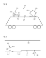
- FIG. 1 shows a pantograph of a rail vehicle, which is used for the capacitive detection of the voltage applied to the contact wire signal.
- FIG. 3 shows a further embodiment.
- the current collector 100 is at minimum operating height 123 at operating speed. Since the contact wire does not always run at the same height, but due to gravity in the form of a rope curve, the pantograph 100 can be tracked while driving the course of the contact wire. Therefore, 133 indicates the position at maximum working height 124 at operating speed. Furthermore, the minimum working height 122 and the maximum working height 125 are shown at reduced speed.
- d Cat-Pan With d Cat-Pan , the distance between the sinker 131 and the contact wire is indicated, wherein the actual distance is unknown due to the cable curve of the contact wire.
- the length of the upper arm 106 is denoted by l Pan
- the distance between the vehicle roof 101 and the frame 103 is designated by d Pan-Roof .
- FIG. 1 the total capacity of the power take-off elements (bus bars, cables) represented by the replacement component C Cable .
- the actual values of all capacities depend on such factors as the height of the overhead line, the geometry of the pantograph and the data of other connected components. Furthermore, environmental influences such as temperature, humidity, contamination of components, etc. can influence the parameters.
- the capacitances C Pan-Roof and C Cable (C Cable is connected in parallel to the C -Roof capacity) can, however, be measured safely and, if necessary, before each acquisition of the contact wire voltage either individually or together in parallel.
- direct metrological measurement can not be performed so that it must either be estimated or assumed on the basis of typical values.
- the device 110 is designed to withstand high voltages.
- the device 110 may be electrically disconnected from the frame 103 and pantograph 100. In both cases, it serves the safety when the pantograph 100 comes into contact with the live contact wire.
- Control of the pantographs ie, evaluation as to whether the preselected operational current system is compatible with the actual operational current system, may be accomplished according to the criteria shown in Table 1 below, systematically referring to the preselected traction current system.
- Table I Requested pantograph for system Detected signal system selection 50 Hz 16.7 Hz Zero / undefined AC 25 kV / 50 Hz x - - System OK, pantograph is lifted - x - Wrong system; Pantograph remains lowered - - x No or wrong system; Pantograph remains lowered AC 15 kV / 16.7 Hz x - - Wrong system; Pantograph remains lowered - x - System OK, pantograph is lifted No or wrong system; Pantograph remains - - x lowered DC 3 kV x - - Wrong system; Pantograph remains lowered - x - Wrong system; Pantograph remains lowered - - x No system or OK, pantograph is lifted
- the system detection described here by contactless detection of the voltage signal also allows a clear distinction between an existing DC voltage and no voltage.
- the harmonic content of the voltage applied to the contact wire is detected. It is thereby exploited the effect that the responsible for the supply of the contact wire substations make the DC voltage by rectifying an AC voltage and thus generate a harmonic-charged DC voltage waveform.
- DC voltages on the contact wire differ in the frequency and amplitude of the harmonics. This can additionally be taken into account when dimensioning the system recognition and signal processing.
- the sensor system can thus have at least one sensor which is insulated from high-voltage components such as the current collectors.
- a capacitive sensor for example in the form of an antenna, is also suitable here, whereby the voltage applied to the contact wire can be detected by a capacitive voltage divider.
- the senor 230 can be used.
Landscapes
- Engineering & Computer Science (AREA)
- Power Engineering (AREA)
- Transportation (AREA)
- Mechanical Engineering (AREA)
- Current-Collector Devices For Electrically Propelled Vehicles (AREA)
- Electric Propulsion And Braking For Vehicles (AREA)
Applications Claiming Priority (1)
| Application Number | Priority Date | Filing Date | Title |
|---|---|---|---|
| DE102011053361A DE102011053361A1 (de) | 2011-09-07 | 2011-09-07 | Vorrichtung zur Auswahl eines Stromabnehmers eines Schienenfahrzeugs sowie Verfahren zum kontaktlosen Erkennen eines Spannungssystems |
Publications (3)
| Publication Number | Publication Date |
|---|---|
| EP2567855A2 true EP2567855A2 (fr) | 2013-03-13 |
| EP2567855A3 EP2567855A3 (fr) | 2014-08-20 |
| EP2567855B1 EP2567855B1 (fr) | 2021-11-17 |
Family
ID=47018765
Family Applications (1)
| Application Number | Title | Priority Date | Filing Date |
|---|---|---|---|
| EP12183321.4A Active EP2567855B1 (fr) | 2011-09-07 | 2012-09-06 | Dispositif de sélection d'une prise de courant d'un véhicule sur rail ainsi que procédé de détection sans contact d'un système de tension |
Country Status (2)
| Country | Link |
|---|---|
| EP (1) | EP2567855B1 (fr) |
| DE (1) | DE102011053361A1 (fr) |
Cited By (2)
| Publication number | Priority date | Publication date | Assignee | Title |
|---|---|---|---|---|
| EP3182142A1 (fr) | 2015-12-15 | 2017-06-21 | Bombardier Transportation GmbH | Dispositif destiné à reconnaître un système de tension |
| CN111907334A (zh) * | 2019-06-18 | 2020-11-10 | 中车大同电力机车有限公司 | 受电弓及其控制方法、电力机车 |
Families Citing this family (2)
| Publication number | Priority date | Publication date | Assignee | Title |
|---|---|---|---|---|
| DE102023209880A1 (de) * | 2023-10-10 | 2025-04-10 | Siemens Mobility GmbH | Verfahren zur Auswahl eines Stromabnehmers bei einem Schienenfahrzeug |
| DE102024203935A1 (de) * | 2024-04-26 | 2025-10-30 | Siemens Mobility GmbH | Stromabnehmer für elektrisch antreibbare Fahrzeuge zur Abnahme von Gleichstrom und Wechselstrom |
Citations (4)
| Publication number | Priority date | Publication date | Assignee | Title |
|---|---|---|---|---|
| DE1225695B (de) | 1963-11-27 | 1966-09-29 | Siemens Ag | Einrichtung zum Anstellen von dem jeweiligen Stromsystem zugeordneten Stromabnehmernauf Mehrsystem-Triebfahrzeugen unter Verwendung von Systemfuehlern |
| JPH09261803A (ja) | 1996-03-26 | 1997-10-03 | Toshiba Transport Eng Kk | 交直両用電気車の制御装置 |
| DE19727218C1 (de) | 1997-06-26 | 1999-03-11 | Siemens Ag | Diskriminatorschaltung zur Unterscheidung von Hochspannungs-Gleichspannung und Hochspannungs-Wechselspannung |
| CA2755340A1 (fr) | 2009-03-13 | 2010-09-16 | Masayuki Nogi | Systeme de vehicule ferroviaire et procede de commande associe |
Family Cites Families (8)
| Publication number | Priority date | Publication date | Assignee | Title |
|---|---|---|---|---|
| US4121154A (en) * | 1975-10-14 | 1978-10-17 | The United States Of America As Represented By The Secretary Of The Interior | Alternating current potential measuring device |
| DE3241680A1 (de) * | 1982-11-11 | 1984-05-17 | Dornier System Gmbh, 7990 Friedrichshafen | Vorrichtung zum feststellen des anliegens eines stromabnehmers einer elektrischen lokomotive am fahrdraht |
| DE19742623C2 (de) * | 1997-09-26 | 2002-06-13 | Siemens Ag | Betriebsverfahren für ein Stromversorgungssystem eines Mehrsystem-Schienenfahzeugs und Stromversorgungssystem eines Mehrsystem-Schienenfahzeugs |
| US6828767B2 (en) * | 2002-03-20 | 2004-12-07 | Santronics, Inc. | Hand-held voltage detection probe |
| FR2926391B1 (fr) * | 2008-01-15 | 2017-06-09 | Alstom Transport Sa | Dispositif de commutation dispose sur un vehicule a alimentation electrique |
| JP2010183802A (ja) * | 2009-02-09 | 2010-08-19 | Kawasaki Heavy Ind Ltd | パンタグラフ昇降制御装置 |
| JP5259820B2 (ja) * | 2009-06-15 | 2013-08-07 | 株式会社日立製作所 | 鉄道車両の駆動システム |
| KR100994164B1 (ko) * | 2010-04-06 | 2010-11-12 | 한국해양대학교 산학협력단 | 직류 전차선의 비접촉식 검전기 |
-
2011
- 2011-09-07 DE DE102011053361A patent/DE102011053361A1/de not_active Ceased
-
2012
- 2012-09-06 EP EP12183321.4A patent/EP2567855B1/fr active Active
Patent Citations (4)
| Publication number | Priority date | Publication date | Assignee | Title |
|---|---|---|---|---|
| DE1225695B (de) | 1963-11-27 | 1966-09-29 | Siemens Ag | Einrichtung zum Anstellen von dem jeweiligen Stromsystem zugeordneten Stromabnehmernauf Mehrsystem-Triebfahrzeugen unter Verwendung von Systemfuehlern |
| JPH09261803A (ja) | 1996-03-26 | 1997-10-03 | Toshiba Transport Eng Kk | 交直両用電気車の制御装置 |
| DE19727218C1 (de) | 1997-06-26 | 1999-03-11 | Siemens Ag | Diskriminatorschaltung zur Unterscheidung von Hochspannungs-Gleichspannung und Hochspannungs-Wechselspannung |
| CA2755340A1 (fr) | 2009-03-13 | 2010-09-16 | Masayuki Nogi | Systeme de vehicule ferroviaire et procede de commande associe |
Cited By (3)
| Publication number | Priority date | Publication date | Assignee | Title |
|---|---|---|---|---|
| EP3182142A1 (fr) | 2015-12-15 | 2017-06-21 | Bombardier Transportation GmbH | Dispositif destiné à reconnaître un système de tension |
| DE102015121876A1 (de) | 2015-12-15 | 2017-06-22 | Bombardier Transportation Gmbh | Vorrichtung zum Erkennen eines Spannungssystems |
| CN111907334A (zh) * | 2019-06-18 | 2020-11-10 | 中车大同电力机车有限公司 | 受电弓及其控制方法、电力机车 |
Also Published As
| Publication number | Publication date |
|---|---|
| EP2567855B1 (fr) | 2021-11-17 |
| EP2567855A3 (fr) | 2014-08-20 |
| DE102011053361A1 (de) | 2013-03-07 |
Similar Documents
| Publication | Publication Date | Title |
|---|---|---|
| EP3616972B1 (fr) | Procédé de commande d'un dispositif de charge à l'extérieur du véhicule et dispositif de charge | |
| DE102017104110B4 (de) | Verfahren und Vorrichtung zur Verlustfaktorüberwachung von Kondensatordurchführungen | |
| WO2018158235A1 (fr) | Pantographe comprenant des contacts de compensation | |
| DE102013215785B4 (de) | Fahrzeugseitiges Lademodul, induktives Ladesystem und Verfahren zum induktiven Laden eines Energiespeichers | |
| EP2567855B1 (fr) | Dispositif de sélection d'une prise de courant d'un véhicule sur rail ainsi que procédé de détection sans contact d'un système de tension | |
| DE102015111015A1 (de) | Verfahren und Vorrichtung zum Lokalisieren eines Batteriemodules unter mehreren untereinander elektrisch verbundenen Batteriemodulen einer Traktionsbatterie | |
| DE102019109260B4 (de) | Verfahren zum Laden eines Fahrzeugs und Fahrzeug | |
| DE102022201190B3 (de) | Erfassung von symmetrischen und asymmetrischen Isolationsfehlern durch asymmetrisch schaltbare Fehlerstromerfassung | |
| EP3941777A1 (fr) | Transfert de signal via une caténaire | |
| EP3182142B1 (fr) | Dispositif destiné à reconnaître un système de tension | |
| WO1993003389A1 (fr) | Procede et dispositif de controle et de localisation de courts-circuits electriques dans des fils conducteurs, notamment des catenaires de voies de chemins de fer electriques | |
| WO2023117090A1 (fr) | Alimentation électrique d'une unité de détection | |
| EP3988951B1 (fr) | Agencement doté d'un module de serrage | |
| WO2016150658A1 (fr) | Dispositif de protection, système et procédé pour une protection d'écartement d'une caténaire d'une alimentation électrique de traction ferroviaire | |
| EP2998750A1 (fr) | Procede et systeme pour la determination de localisation de defaut en cas de court-circuit le long d'une section d'alimentation d'energie a plusieurs conducteurs | |
| WO2024017773A1 (fr) | Véhicule ayant un système électrique embarqué à haute tension et procédé de fonctionnement du système électrique embarqué à haute tension | |
| EP2773001B1 (fr) | Dispositif de sécurité électrique et son procédé adapté à un moyen de transport sur rails sans conducteur | |
| EP2685581A1 (fr) | Alimentation d'un véhicule sur rails en énergie électrique par le biais d'une ligne blindée d'alimentation en énergie | |
| EP3385731B1 (fr) | Dispositif de mesure de courant de fuite à la terre | |
| EP4471439B1 (fr) | Dispositif d'alimentation électrique, véhicule et procédé de surveillance d'une perte de contact d'une ligne de mesure | |
| DE4412250C2 (de) | Streckenprüfeinrichtung zur Prüfung des Isolationszustandes von an Wechselspannung liegenden Bahnfahrleitungen | |
| DE19950513A1 (de) | Verfahren zur Erfassung und Überwachung der Berührungsspannung am Chassis von Trolleybussen sowie Einrichtung zur Durchführung des Verfahrens | |
| DE102021005425A1 (de) | System zur berührungslosen Energieübertragung und Verfahren zum Betreiben eines Systems zur berührungslosen Energeieübertagung | |
| DE102021005551A1 (de) | System zur berührungslosen Energieübertragung und Verfahren zum Betreiben eines Systems zur berührungslosen Energieübertragung | |
| DE102020130863A1 (de) | Verfahren zur automatisierten Erkennung einer Schaltmatrix von an ein Dreiphasen-Verteilnetz angeschlossenen elektrischen Verbrauchsmitteln, insbesondere von Ladeeinrichtungen für elektrische Energiespeicher sowie Ladeeinrichtung |
Legal Events
| Date | Code | Title | Description |
|---|---|---|---|
| PUAI | Public reference made under article 153(3) epc to a published international application that has entered the european phase |
Free format text: ORIGINAL CODE: 0009012 |
|
| AK | Designated contracting states |
Kind code of ref document: A2 Designated state(s): AL AT BE BG CH CY CZ DE DK EE ES FI FR GB GR HR HU IE IS IT LI LT LU LV MC MK MT NL NO PL PT RO RS SE SI SK SM TR |
|
| AX | Request for extension of the european patent |
Extension state: BA ME |
|
| PUAL | Search report despatched |
Free format text: ORIGINAL CODE: 0009013 |
|
| AK | Designated contracting states |
Kind code of ref document: A3 Designated state(s): AL AT BE BG CH CY CZ DE DK EE ES FI FR GB GR HR HU IE IS IT LI LT LU LV MC MK MT NL NO PL PT RO RS SE SI SK SM TR |
|
| AX | Request for extension of the european patent |
Extension state: BA ME |
|
| RIC1 | Information provided on ipc code assigned before grant |
Ipc: B60L 5/18 20060101AFI20140716BHEP |
|
| 17P | Request for examination filed |
Effective date: 20150220 |
|
| RBV | Designated contracting states (corrected) |
Designated state(s): AL AT BE BG CH CY CZ DE DK EE ES FI FR GB GR HR HU IE IS IT LI LT LU LV MC MK MT NL NO PL PT RO RS SE SI SK SM TR |
|
| STAA | Information on the status of an ep patent application or granted ep patent |
Free format text: STATUS: EXAMINATION IS IN PROGRESS |
|
| 17Q | First examination report despatched |
Effective date: 20170424 |
|
| RAP1 | Party data changed (applicant data changed or rights of an application transferred) |
Owner name: BOMBARDIER TRANSPORTATION GMBH |
|
| GRAP | Despatch of communication of intention to grant a patent |
Free format text: ORIGINAL CODE: EPIDOSNIGR1 |
|
| STAA | Information on the status of an ep patent application or granted ep patent |
Free format text: STATUS: GRANT OF PATENT IS INTENDED |
|
| INTG | Intention to grant announced |
Effective date: 20190903 |
|
| GRAJ | Information related to disapproval of communication of intention to grant by the applicant or resumption of examination proceedings by the epo deleted |
Free format text: ORIGINAL CODE: EPIDOSDIGR1 |
|
| STAA | Information on the status of an ep patent application or granted ep patent |
Free format text: STATUS: EXAMINATION IS IN PROGRESS |
|
| INTC | Intention to grant announced (deleted) | ||
| GRAP | Despatch of communication of intention to grant a patent |
Free format text: ORIGINAL CODE: EPIDOSNIGR1 |
|
| STAA | Information on the status of an ep patent application or granted ep patent |
Free format text: STATUS: GRANT OF PATENT IS INTENDED |
|
| INTG | Intention to grant announced |
Effective date: 20210125 |
|
| GRAJ | Information related to disapproval of communication of intention to grant by the applicant or resumption of examination proceedings by the epo deleted |
Free format text: ORIGINAL CODE: EPIDOSDIGR1 |
|
| STAA | Information on the status of an ep patent application or granted ep patent |
Free format text: STATUS: EXAMINATION IS IN PROGRESS |
|
| GRAP | Despatch of communication of intention to grant a patent |
Free format text: ORIGINAL CODE: EPIDOSNIGR1 |
|
| STAA | Information on the status of an ep patent application or granted ep patent |
Free format text: STATUS: GRANT OF PATENT IS INTENDED |
|
| INTC | Intention to grant announced (deleted) | ||
| INTG | Intention to grant announced |
Effective date: 20210622 |
|
| GRAS | Grant fee paid |
Free format text: ORIGINAL CODE: EPIDOSNIGR3 |
|
| GRAA | (expected) grant |
Free format text: ORIGINAL CODE: 0009210 |
|
| STAA | Information on the status of an ep patent application or granted ep patent |
Free format text: STATUS: THE PATENT HAS BEEN GRANTED |
|
| AK | Designated contracting states |
Kind code of ref document: B1 Designated state(s): AL AT BE BG CH CY CZ DE DK EE ES FI FR GB GR HR HU IE IS IT LI LT LU LV MC MK MT NL NO PL PT RO RS SE SI SK SM TR |
|
| REG | Reference to a national code |
Ref country code: GB Ref legal event code: FG4D Free format text: NOT ENGLISH |
|
| REG | Reference to a national code |
Ref country code: DE Ref legal event code: R096 Ref document number: 502012016942 Country of ref document: DE |
|
| REG | Reference to a national code |
Ref country code: IE Ref legal event code: FG4D Free format text: LANGUAGE OF EP DOCUMENT: GERMAN |
|
| REG | Reference to a national code |
Ref country code: AT Ref legal event code: REF Ref document number: 1447775 Country of ref document: AT Kind code of ref document: T Effective date: 20211215 |
|
| REG | Reference to a national code |
Ref country code: LT Ref legal event code: MG9D |
|
| REG | Reference to a national code |
Ref country code: NL Ref legal event code: MP Effective date: 20211117 |
|
| PG25 | Lapsed in a contracting state [announced via postgrant information from national office to epo] |
Ref country code: RS Free format text: LAPSE BECAUSE OF FAILURE TO SUBMIT A TRANSLATION OF THE DESCRIPTION OR TO PAY THE FEE WITHIN THE PRESCRIBED TIME-LIMIT Effective date: 20211117 Ref country code: LT Free format text: LAPSE BECAUSE OF FAILURE TO SUBMIT A TRANSLATION OF THE DESCRIPTION OR TO PAY THE FEE WITHIN THE PRESCRIBED TIME-LIMIT Effective date: 20211117 Ref country code: FI Free format text: LAPSE BECAUSE OF FAILURE TO SUBMIT A TRANSLATION OF THE DESCRIPTION OR TO PAY THE FEE WITHIN THE PRESCRIBED TIME-LIMIT Effective date: 20211117 Ref country code: BG Free format text: LAPSE BECAUSE OF FAILURE TO SUBMIT A TRANSLATION OF THE DESCRIPTION OR TO PAY THE FEE WITHIN THE PRESCRIBED TIME-LIMIT Effective date: 20220217 |
|
| PG25 | Lapsed in a contracting state [announced via postgrant information from national office to epo] |
Ref country code: IS Free format text: LAPSE BECAUSE OF FAILURE TO SUBMIT A TRANSLATION OF THE DESCRIPTION OR TO PAY THE FEE WITHIN THE PRESCRIBED TIME-LIMIT Effective date: 20220317 Ref country code: SE Free format text: LAPSE BECAUSE OF FAILURE TO SUBMIT A TRANSLATION OF THE DESCRIPTION OR TO PAY THE FEE WITHIN THE PRESCRIBED TIME-LIMIT Effective date: 20211117 Ref country code: PT Free format text: LAPSE BECAUSE OF FAILURE TO SUBMIT A TRANSLATION OF THE DESCRIPTION OR TO PAY THE FEE WITHIN THE PRESCRIBED TIME-LIMIT Effective date: 20220317 Ref country code: PL Free format text: LAPSE BECAUSE OF FAILURE TO SUBMIT A TRANSLATION OF THE DESCRIPTION OR TO PAY THE FEE WITHIN THE PRESCRIBED TIME-LIMIT Effective date: 20211117 Ref country code: NO Free format text: LAPSE BECAUSE OF FAILURE TO SUBMIT A TRANSLATION OF THE DESCRIPTION OR TO PAY THE FEE WITHIN THE PRESCRIBED TIME-LIMIT Effective date: 20220217 Ref country code: NL Free format text: LAPSE BECAUSE OF FAILURE TO SUBMIT A TRANSLATION OF THE DESCRIPTION OR TO PAY THE FEE WITHIN THE PRESCRIBED TIME-LIMIT Effective date: 20211117 Ref country code: LV Free format text: LAPSE BECAUSE OF FAILURE TO SUBMIT A TRANSLATION OF THE DESCRIPTION OR TO PAY THE FEE WITHIN THE PRESCRIBED TIME-LIMIT Effective date: 20211117 Ref country code: HR Free format text: LAPSE BECAUSE OF FAILURE TO SUBMIT A TRANSLATION OF THE DESCRIPTION OR TO PAY THE FEE WITHIN THE PRESCRIBED TIME-LIMIT Effective date: 20211117 Ref country code: GR Free format text: LAPSE BECAUSE OF FAILURE TO SUBMIT A TRANSLATION OF THE DESCRIPTION OR TO PAY THE FEE WITHIN THE PRESCRIBED TIME-LIMIT Effective date: 20220218 Ref country code: ES Free format text: LAPSE BECAUSE OF FAILURE TO SUBMIT A TRANSLATION OF THE DESCRIPTION OR TO PAY THE FEE WITHIN THE PRESCRIBED TIME-LIMIT Effective date: 20211117 |
|
| PG25 | Lapsed in a contracting state [announced via postgrant information from national office to epo] |
Ref country code: SM Free format text: LAPSE BECAUSE OF FAILURE TO SUBMIT A TRANSLATION OF THE DESCRIPTION OR TO PAY THE FEE WITHIN THE PRESCRIBED TIME-LIMIT Effective date: 20211117 Ref country code: SK Free format text: LAPSE BECAUSE OF FAILURE TO SUBMIT A TRANSLATION OF THE DESCRIPTION OR TO PAY THE FEE WITHIN THE PRESCRIBED TIME-LIMIT Effective date: 20211117 Ref country code: RO Free format text: LAPSE BECAUSE OF FAILURE TO SUBMIT A TRANSLATION OF THE DESCRIPTION OR TO PAY THE FEE WITHIN THE PRESCRIBED TIME-LIMIT Effective date: 20211117 Ref country code: EE Free format text: LAPSE BECAUSE OF FAILURE TO SUBMIT A TRANSLATION OF THE DESCRIPTION OR TO PAY THE FEE WITHIN THE PRESCRIBED TIME-LIMIT Effective date: 20211117 Ref country code: DK Free format text: LAPSE BECAUSE OF FAILURE TO SUBMIT A TRANSLATION OF THE DESCRIPTION OR TO PAY THE FEE WITHIN THE PRESCRIBED TIME-LIMIT Effective date: 20211117 Ref country code: CZ Free format text: LAPSE BECAUSE OF FAILURE TO SUBMIT A TRANSLATION OF THE DESCRIPTION OR TO PAY THE FEE WITHIN THE PRESCRIBED TIME-LIMIT Effective date: 20211117 |
|
| REG | Reference to a national code |
Ref country code: DE Ref legal event code: R097 Ref document number: 502012016942 Country of ref document: DE |
|
| PLBE | No opposition filed within time limit |
Free format text: ORIGINAL CODE: 0009261 |
|
| STAA | Information on the status of an ep patent application or granted ep patent |
Free format text: STATUS: NO OPPOSITION FILED WITHIN TIME LIMIT |
|
| 26N | No opposition filed |
Effective date: 20220818 |
|
| PG25 | Lapsed in a contracting state [announced via postgrant information from national office to epo] |
Ref country code: AL Free format text: LAPSE BECAUSE OF FAILURE TO SUBMIT A TRANSLATION OF THE DESCRIPTION OR TO PAY THE FEE WITHIN THE PRESCRIBED TIME-LIMIT Effective date: 20211117 |
|
| PG25 | Lapsed in a contracting state [announced via postgrant information from national office to epo] |
Ref country code: SI Free format text: LAPSE BECAUSE OF FAILURE TO SUBMIT A TRANSLATION OF THE DESCRIPTION OR TO PAY THE FEE WITHIN THE PRESCRIBED TIME-LIMIT Effective date: 20211117 |
|
| PG25 | Lapsed in a contracting state [announced via postgrant information from national office to epo] |
Ref country code: MC Free format text: LAPSE BECAUSE OF FAILURE TO SUBMIT A TRANSLATION OF THE DESCRIPTION OR TO PAY THE FEE WITHIN THE PRESCRIBED TIME-LIMIT Effective date: 20211117 |
|
| GBPC | Gb: european patent ceased through non-payment of renewal fee |
Effective date: 20220906 |
|
| REG | Reference to a national code |
Ref country code: BE Ref legal event code: MM Effective date: 20220930 |
|
| PG25 | Lapsed in a contracting state [announced via postgrant information from national office to epo] |
Ref country code: IT Free format text: LAPSE BECAUSE OF FAILURE TO SUBMIT A TRANSLATION OF THE DESCRIPTION OR TO PAY THE FEE WITHIN THE PRESCRIBED TIME-LIMIT Effective date: 20211117 |
|
| PG25 | Lapsed in a contracting state [announced via postgrant information from national office to epo] |
Ref country code: LU Free format text: LAPSE BECAUSE OF NON-PAYMENT OF DUE FEES Effective date: 20220906 |
|
| PG25 | Lapsed in a contracting state [announced via postgrant information from national office to epo] |
Ref country code: IE Free format text: LAPSE BECAUSE OF NON-PAYMENT OF DUE FEES Effective date: 20220906 |
|
| P01 | Opt-out of the competence of the unified patent court (upc) registered |
Effective date: 20230822 |
|
| PG25 | Lapsed in a contracting state [announced via postgrant information from national office to epo] |
Ref country code: BE Free format text: LAPSE BECAUSE OF NON-PAYMENT OF DUE FEES Effective date: 20220930 |
|
| PG25 | Lapsed in a contracting state [announced via postgrant information from national office to epo] |
Ref country code: GB Free format text: LAPSE BECAUSE OF NON-PAYMENT OF DUE FEES Effective date: 20220906 |
|
| REG | Reference to a national code |
Ref country code: AT Ref legal event code: MM01 Ref document number: 1447775 Country of ref document: AT Kind code of ref document: T Effective date: 20220906 |
|
| PG25 | Lapsed in a contracting state [announced via postgrant information from national office to epo] |
Ref country code: AT Free format text: LAPSE BECAUSE OF NON-PAYMENT OF DUE FEES Effective date: 20220906 |
|
| PG25 | Lapsed in a contracting state [announced via postgrant information from national office to epo] |
Ref country code: HU Free format text: LAPSE BECAUSE OF FAILURE TO SUBMIT A TRANSLATION OF THE DESCRIPTION OR TO PAY THE FEE WITHIN THE PRESCRIBED TIME-LIMIT; INVALID AB INITIO Effective date: 20120906 |
|
| PG25 | Lapsed in a contracting state [announced via postgrant information from national office to epo] |
Ref country code: CY Free format text: LAPSE BECAUSE OF FAILURE TO SUBMIT A TRANSLATION OF THE DESCRIPTION OR TO PAY THE FEE WITHIN THE PRESCRIBED TIME-LIMIT Effective date: 20211117 |
|
| PG25 | Lapsed in a contracting state [announced via postgrant information from national office to epo] |
Ref country code: MK Free format text: LAPSE BECAUSE OF FAILURE TO SUBMIT A TRANSLATION OF THE DESCRIPTION OR TO PAY THE FEE WITHIN THE PRESCRIBED TIME-LIMIT Effective date: 20211117 |
|
| PG25 | Lapsed in a contracting state [announced via postgrant information from national office to epo] |
Ref country code: TR Free format text: LAPSE BECAUSE OF FAILURE TO SUBMIT A TRANSLATION OF THE DESCRIPTION OR TO PAY THE FEE WITHIN THE PRESCRIBED TIME-LIMIT Effective date: 20211117 |
|
| PG25 | Lapsed in a contracting state [announced via postgrant information from national office to epo] |
Ref country code: MT Free format text: LAPSE BECAUSE OF FAILURE TO SUBMIT A TRANSLATION OF THE DESCRIPTION OR TO PAY THE FEE WITHIN THE PRESCRIBED TIME-LIMIT Effective date: 20211117 |
|
| PGFP | Annual fee paid to national office [announced via postgrant information from national office to epo] |
Ref country code: DE Payment date: 20240918 Year of fee payment: 13 |
|
| PGFP | Annual fee paid to national office [announced via postgrant information from national office to epo] |
Ref country code: FR Payment date: 20240925 Year of fee payment: 13 |
|
| PGFP | Annual fee paid to national office [announced via postgrant information from national office to epo] |
Ref country code: CH Payment date: 20241001 Year of fee payment: 13 |
|
| REG | Reference to a national code |
Ref country code: CH Ref legal event code: H13 Free format text: ST27 STATUS EVENT CODE: U-0-0-H10-H13 (AS PROVIDED BY THE NATIONAL OFFICE) Effective date: 20260425 |