EP2567902A1 - Dispositif d'application d'une étiquette sur un récipient - Google Patents
Dispositif d'application d'une étiquette sur un récipient Download PDFInfo
- Publication number
- EP2567902A1 EP2567902A1 EP12169291A EP12169291A EP2567902A1 EP 2567902 A1 EP2567902 A1 EP 2567902A1 EP 12169291 A EP12169291 A EP 12169291A EP 12169291 A EP12169291 A EP 12169291A EP 2567902 A1 EP2567902 A1 EP 2567902A1
- Authority
- EP
- European Patent Office
- Prior art keywords
- adhesive
- solvent
- pallet
- surface area
- label
- Prior art date
- Legal status (The legal status is an assumption and is not a legal conclusion. Google has not performed a legal analysis and makes no representation as to the accuracy of the status listed.)
- Granted
Links
- 239000000853 adhesive Substances 0.000 claims abstract description 237
- 230000001070 adhesive effect Effects 0.000 claims abstract description 232
- 239000002904 solvent Substances 0.000 claims abstract description 105
- 238000000034 method Methods 0.000 claims abstract description 5
- 238000004140 cleaning Methods 0.000 claims description 54
- 239000007788 liquid Substances 0.000 claims description 27
- 239000011148 porous material Substances 0.000 claims description 22
- 238000002372 labelling Methods 0.000 claims description 19
- 238000010438 heat treatment Methods 0.000 claims description 10
- 239000000463 material Substances 0.000 claims description 10
- 239000012528 membrane Substances 0.000 claims description 10
- 239000003292 glue Substances 0.000 description 22
- 239000007921 spray Substances 0.000 description 13
- 238000001816 cooling Methods 0.000 description 8
- CSCPPACGZOOCGX-UHFFFAOYSA-N Acetone Chemical compound CC(C)=O CSCPPACGZOOCGX-UHFFFAOYSA-N 0.000 description 6
- YMWUJEATGCHHMB-UHFFFAOYSA-N Dichloromethane Chemical compound ClCCl YMWUJEATGCHHMB-UHFFFAOYSA-N 0.000 description 6
- ZMXDDKWLCZADIW-UHFFFAOYSA-N N,N-Dimethylformamide Chemical compound CN(C)C=O ZMXDDKWLCZADIW-UHFFFAOYSA-N 0.000 description 6
- 239000013505 freshwater Substances 0.000 description 6
- 239000003960 organic solvent Substances 0.000 description 6
- 239000004033 plastic Substances 0.000 description 6
- 229920003023 plastic Polymers 0.000 description 6
- -1 polyethylene terephthalate Polymers 0.000 description 6
- XLYOFNOQVPJJNP-UHFFFAOYSA-N water Substances O XLYOFNOQVPJJNP-UHFFFAOYSA-N 0.000 description 6
- ZWEHNKRNPOVVGH-UHFFFAOYSA-N 2-Butanone Chemical compound CCC(C)=O ZWEHNKRNPOVVGH-UHFFFAOYSA-N 0.000 description 5
- LYCAIKOWRPUZTN-UHFFFAOYSA-N Ethylene glycol Chemical compound OCCO LYCAIKOWRPUZTN-UHFFFAOYSA-N 0.000 description 5
- 238000009529 body temperature measurement Methods 0.000 description 5
- WYURNTSHIVDZCO-UHFFFAOYSA-N Tetrahydrofuran Chemical compound C1CCOC1 WYURNTSHIVDZCO-UHFFFAOYSA-N 0.000 description 4
- JHIVVAPYMSGYDF-UHFFFAOYSA-N cyclohexanone Chemical compound O=C1CCCCC1 JHIVVAPYMSGYDF-UHFFFAOYSA-N 0.000 description 4
- 239000012530 fluid Substances 0.000 description 4
- 239000000203 mixture Substances 0.000 description 4
- 238000005496 tempering Methods 0.000 description 4
- 238000012546 transfer Methods 0.000 description 4
- WEVYAHXRMPXWCK-UHFFFAOYSA-N Acetonitrile Chemical compound CC#N WEVYAHXRMPXWCK-UHFFFAOYSA-N 0.000 description 3
- UHOVQNZJYSORNB-UHFFFAOYSA-N Benzene Chemical compound C1=CC=CC=C1 UHOVQNZJYSORNB-UHFFFAOYSA-N 0.000 description 3
- RTZKZFJDLAIYFH-UHFFFAOYSA-N Diethyl ether Chemical compound CCOCC RTZKZFJDLAIYFH-UHFFFAOYSA-N 0.000 description 3
- XEKOWRVHYACXOJ-UHFFFAOYSA-N Ethyl acetate Chemical compound CCOC(C)=O XEKOWRVHYACXOJ-UHFFFAOYSA-N 0.000 description 3
- 239000004831 Hot glue Substances 0.000 description 3
- OKKJLVBELUTLKV-UHFFFAOYSA-N Methanol Chemical compound OC OKKJLVBELUTLKV-UHFFFAOYSA-N 0.000 description 3
- YXFVVABEGXRONW-UHFFFAOYSA-N Toluene Chemical compound CC1=CC=CC=C1 YXFVVABEGXRONW-UHFFFAOYSA-N 0.000 description 3
- 239000012790 adhesive layer Substances 0.000 description 3
- 230000033228 biological regulation Effects 0.000 description 3
- 239000003638 chemical reducing agent Substances 0.000 description 3
- MTHSVFCYNBDYFN-UHFFFAOYSA-N diethylene glycol Chemical compound OCCOCCO MTHSVFCYNBDYFN-UHFFFAOYSA-N 0.000 description 3
- 150000002170 ethers Chemical class 0.000 description 3
- 230000001105 regulatory effect Effects 0.000 description 3
- HEDRZPFGACZZDS-UHFFFAOYSA-N Chloroform Chemical compound ClC(Cl)Cl HEDRZPFGACZZDS-UHFFFAOYSA-N 0.000 description 2
- IAZDPXIOMUYVGZ-UHFFFAOYSA-N Dimethylsulphoxide Chemical compound CS(C)=O IAZDPXIOMUYVGZ-UHFFFAOYSA-N 0.000 description 2
- LFQSCWFLJHTTHZ-UHFFFAOYSA-N Ethanol Chemical compound CCO LFQSCWFLJHTTHZ-UHFFFAOYSA-N 0.000 description 2
- SECXISVLQFMRJM-UHFFFAOYSA-N N-Methylpyrrolidone Chemical compound CN1CCCC1=O SECXISVLQFMRJM-UHFFFAOYSA-N 0.000 description 2
- JUJWROOIHBZHMG-UHFFFAOYSA-N Pyridine Chemical compound C1=CC=NC=C1 JUJWROOIHBZHMG-UHFFFAOYSA-N 0.000 description 2
- 210000001015 abdomen Anatomy 0.000 description 2
- RDOXTESZEPMUJZ-UHFFFAOYSA-N anisole Chemical compound COC1=CC=CC=C1 RDOXTESZEPMUJZ-UHFFFAOYSA-N 0.000 description 2
- 239000000919 ceramic Substances 0.000 description 2
- NNBZCPXTIHJBJL-UHFFFAOYSA-N decalin Chemical compound C1CCCC2CCCCC21 NNBZCPXTIHJBJL-UHFFFAOYSA-N 0.000 description 2
- 238000013461 design Methods 0.000 description 2
- 230000001066 destructive effect Effects 0.000 description 2
- 235000019439 ethyl acetate Nutrition 0.000 description 2
- WGCNASOHLSPBMP-UHFFFAOYSA-N hydroxyacetaldehyde Natural products OCC=O WGCNASOHLSPBMP-UHFFFAOYSA-N 0.000 description 2
- 230000006698 induction Effects 0.000 description 2
- 150000002576 ketones Chemical class 0.000 description 2
- UAEPNZWRGJTJPN-UHFFFAOYSA-N methylcyclohexane Chemical compound CC1CCCCC1 UAEPNZWRGJTJPN-UHFFFAOYSA-N 0.000 description 2
- LQNUZADURLCDLV-UHFFFAOYSA-N nitrobenzene Chemical compound [O-][N+](=O)C1=CC=CC=C1 LQNUZADURLCDLV-UHFFFAOYSA-N 0.000 description 2
- 229920000139 polyethylene terephthalate Polymers 0.000 description 2
- 239000005020 polyethylene terephthalate Substances 0.000 description 2
- VZGDMQKNWNREIO-UHFFFAOYSA-N tetrachloromethane Chemical compound ClC(Cl)(Cl)Cl VZGDMQKNWNREIO-UHFFFAOYSA-N 0.000 description 2
- YLQBMQCUIZJEEH-UHFFFAOYSA-N tetrahydrofuran Natural products C=1C=COC=1 YLQBMQCUIZJEEH-UHFFFAOYSA-N 0.000 description 2
- WSLDOOZREJYCGB-UHFFFAOYSA-N 1,2-Dichloroethane Chemical compound ClCCCl WSLDOOZREJYCGB-UHFFFAOYSA-N 0.000 description 1
- RYHBNJHYFVUHQT-UHFFFAOYSA-N 1,4-Dioxane Chemical compound C1COCCO1 RYHBNJHYFVUHQT-UHFFFAOYSA-N 0.000 description 1
- DURPTKYDGMDSBL-UHFFFAOYSA-N 1-butoxybutane Chemical compound CCCCOCCCC DURPTKYDGMDSBL-UHFFFAOYSA-N 0.000 description 1
- OKTJSMMVPCPJKN-UHFFFAOYSA-N Carbon Chemical compound [C] OKTJSMMVPCPJKN-UHFFFAOYSA-N 0.000 description 1
- XDTMQSROBMDMFD-UHFFFAOYSA-N Cyclohexane Chemical compound C1CCCCC1 XDTMQSROBMDMFD-UHFFFAOYSA-N 0.000 description 1
- 239000004593 Epoxy Substances 0.000 description 1
- 241000237858 Gastropoda Species 0.000 description 1
- NTIZESTWPVYFNL-UHFFFAOYSA-N Methyl isobutyl ketone Chemical compound CC(C)CC(C)=O NTIZESTWPVYFNL-UHFFFAOYSA-N 0.000 description 1
- UIHCLUNTQKBZGK-UHFFFAOYSA-N Methyl isobutyl ketone Natural products CCC(C)C(C)=O UIHCLUNTQKBZGK-UHFFFAOYSA-N 0.000 description 1
- LRHPLDYGYMQRHN-UHFFFAOYSA-N N-Butanol Chemical class CCCCO LRHPLDYGYMQRHN-UHFFFAOYSA-N 0.000 description 1
- CYTYCFOTNPOANT-UHFFFAOYSA-N Perchloroethylene Chemical compound ClC(Cl)=C(Cl)Cl CYTYCFOTNPOANT-UHFFFAOYSA-N 0.000 description 1
- 239000002202 Polyethylene glycol Substances 0.000 description 1
- 239000013543 active substance Substances 0.000 description 1
- 150000001298 alcohols Chemical class 0.000 description 1
- 229910052782 aluminium Inorganic materials 0.000 description 1
- XAGFODPZIPBFFR-UHFFFAOYSA-N aluminium Chemical compound [Al] XAGFODPZIPBFFR-UHFFFAOYSA-N 0.000 description 1
- 150000001408 amides Chemical class 0.000 description 1
- 235000013361 beverage Nutrition 0.000 description 1
- 239000011230 binding agent Substances 0.000 description 1
- 229910052799 carbon Inorganic materials 0.000 description 1
- QGJOPFRUJISHPQ-NJFSPNSNSA-N carbon disulfide-14c Chemical compound S=[14C]=S QGJOPFRUJISHPQ-NJFSPNSNSA-N 0.000 description 1
- 230000008878 coupling Effects 0.000 description 1
- 238000010168 coupling process Methods 0.000 description 1
- 238000005859 coupling reaction Methods 0.000 description 1
- 150000004292 cyclic ethers Chemical class 0.000 description 1
- HPXRVTGHNJAIIH-UHFFFAOYSA-N cyclohexanol Chemical compound OC1CCCCC1 HPXRVTGHNJAIIH-UHFFFAOYSA-N 0.000 description 1
- 239000003599 detergent Substances 0.000 description 1
- 238000004090 dissolution Methods 0.000 description 1
- 150000002148 esters Chemical class 0.000 description 1
- 238000011010 flushing procedure Methods 0.000 description 1
- 239000011888 foil Substances 0.000 description 1
- 239000011521 glass Substances 0.000 description 1
- 150000002334 glycols Chemical class 0.000 description 1
- 150000008282 halocarbons Chemical class 0.000 description 1
- 229930195733 hydrocarbon Natural products 0.000 description 1
- 150000002430 hydrocarbons Chemical class 0.000 description 1
- 230000002706 hydrostatic effect Effects 0.000 description 1
- 238000002347 injection Methods 0.000 description 1
- 239000007924 injection Substances 0.000 description 1
- 238000004519 manufacturing process Methods 0.000 description 1
- 229910052751 metal Inorganic materials 0.000 description 1
- 239000002184 metal Substances 0.000 description 1
- UZKWTJUDCOPSNM-UHFFFAOYSA-N methoxybenzene Substances CCCCOC=C UZKWTJUDCOPSNM-UHFFFAOYSA-N 0.000 description 1
- GYNNXHKOJHMOHS-UHFFFAOYSA-N methyl-cycloheptane Natural products CC1CCCCCC1 GYNNXHKOJHMOHS-UHFFFAOYSA-N 0.000 description 1
- 238000000465 moulding Methods 0.000 description 1
- 150000002828 nitro derivatives Chemical class 0.000 description 1
- 229910017464 nitrogen compound Inorganic materials 0.000 description 1
- 150000002830 nitrogen compounds Chemical class 0.000 description 1
- 238000004806 packaging method and process Methods 0.000 description 1
- 230000000737 periodic effect Effects 0.000 description 1
- 239000003208 petroleum Substances 0.000 description 1
- 229920000728 polyester Polymers 0.000 description 1
- 229920001223 polyethylene glycol Polymers 0.000 description 1
- 238000012545 processing Methods 0.000 description 1
- BDERNNFJNOPAEC-UHFFFAOYSA-N propan-1-ol Chemical class CCCO BDERNNFJNOPAEC-UHFFFAOYSA-N 0.000 description 1
- UMJSCPRVCHMLSP-UHFFFAOYSA-N pyridine Natural products COC1=CC=CN=C1 UMJSCPRVCHMLSP-UHFFFAOYSA-N 0.000 description 1
- 238000004064 recycling Methods 0.000 description 1
- 229910001220 stainless steel Inorganic materials 0.000 description 1
- 239000010935 stainless steel Substances 0.000 description 1
- 239000000126 substance Substances 0.000 description 1
- HXJUTPCZVOIRIF-UHFFFAOYSA-N sulfolane Chemical compound O=S1(=O)CCCC1 HXJUTPCZVOIRIF-UHFFFAOYSA-N 0.000 description 1
- 150000003464 sulfur compounds Chemical class 0.000 description 1
- 239000004094 surface-active agent Substances 0.000 description 1
- 150000003505 terpenes Chemical class 0.000 description 1
- 235000007586 terpenes Nutrition 0.000 description 1
- 229950011008 tetrachloroethylene Drugs 0.000 description 1
- PXXNTAGJWPJAGM-UHFFFAOYSA-N vertaline Natural products C1C2C=3C=C(OC)C(OC)=CC=3OC(C=C3)=CC=C3CCC(=O)OC1CC1N2CCCC1 PXXNTAGJWPJAGM-UHFFFAOYSA-N 0.000 description 1
- 239000008096 xylene Substances 0.000 description 1
- 150000003738 xylenes Chemical class 0.000 description 1
Images

Classifications
-
- B—PERFORMING OPERATIONS; TRANSPORTING
- B65—CONVEYING; PACKING; STORING; HANDLING THIN OR FILAMENTARY MATERIAL
- B65C—LABELLING OR TAGGING MACHINES, APPARATUS, OR PROCESSES
- B65C9/00—Details of labelling machines or apparatus
- B65C9/20—Gluing the labels or articles
- B65C9/22—Gluing the labels or articles by wetting, e.g. by applying liquid glue or a liquid to a dry glue coating
- B65C9/2273—Gluing the labels or articles by wetting, e.g. by applying liquid glue or a liquid to a dry glue coating using wipers, pallets or segments
- B65C9/2282—Applying the liquid on the label
-
- B—PERFORMING OPERATIONS; TRANSPORTING
- B65—CONVEYING; PACKING; STORING; HANDLING THIN OR FILAMENTARY MATERIAL
- B65C—LABELLING OR TAGGING MACHINES, APPARATUS, OR PROCESSES
- B65C9/00—Details of labelling machines or apparatus
- B65C9/08—Label feeding
- B65C9/12—Removing separate labels from stacks
- B65C9/16—Removing separate labels from stacks by wetting devices
Definitions
- the present invention relates to a device for applying a label to a container, in particular a labeling device comprising at least one pallet, wherein the at least one pallet comprises a surface area which can be provided with an adhesive and / or solvent and on which a label, in particular temporarily, is arranged can.
- Such devices are known in the art, for example for labeling containers, such as bottles.
- a surface area of a pallet is provided with an adhesive, typically with a glue. This is usually done by passing the surface area past a rotating glue roller on the outer surface of which the glue is provided.
- a label is taken over by a supply device in such a way that the label temporarily sticks to the pallet. This will transfer part of the adhesive to the back of the label.
- a gripper then removes the label from the surface area of the pallet and then transfers the glued-coated label to the container to be labeled.
- Such devices are for example from the DE 35 42 848 or the DE 100 45 960 known.
- central glue supply devices are also in use.
- Such central glue supply facilities are for example from the WO 2009/036869 or the DE 295 19 876 known.
- the invention provides a device for applying a label to a container, in particular a labeling device, comprising at least one pallet, wherein the at least one pallet comprises a surface area which can be provided with an adhesive and / or solvent and on which a label, in particular temporarily, is arranged can be, characterized in that the at least one pallet comprises a pallet body and an adhesive element connected thereto, wherein the surface area which can be provided with an adhesive and / or solvent is arranged on one side of the adhesive element and wherein the adhesive and / or solvent is provided for the surface area which can be provided with an adhesive and / or solvent can be supplied via another side of the adhesive element.
- the device By allowing the adhesive and / or solvent to be supplied through a side other than that to which the adhesive and / or solvent and the label are to be placed, the device can be made simpler and more compact. For example, can be dispensed with a glue roller.
- the adhesive and / or solvent can be supplied via the pallet itself to the surface area which can be provided with an adhesive and / or solvent.
- the at least one pallet in particular the adhesive element of the at least one pallet, can be designed such that an adhesive and / or solvent can be passed at least partially through the adhesive element.
- the device for applying a label to a container may in particular be a labeling device or a labeling unit.
- the device may in particular be a labeling device in the food industry, in particular in the beverage industry.
- the device may also be part of a labeling device.
- Labels within the meaning of the invention may also be labels, security labels or the like. Labels may be in particular printed paper or plastic blanks or Stanniolzubalde. The labels may in particular include logos, images, text and / or relief-like structures.
- Containers may be, for example, bottles, cans, ampoules or other packaging.
- bottles can be glass or plastic bottles, for example PET (polyethylene terephthalate) slugs.
- PET polyethylene terephthalate
- the containers can, for example, be guided past the device for applying a label by means of a turntable.
- labels can be applied to one or more containers.
- one or more labels can be applied to each container.
- several labels may be vertically offset on a container to be ordered.
- a belly label for the bottle belly and a neck label for the bottleneck may be provided.
- the adhesive may be glue, in particular cold glue or hot glue.
- the solvent may be, for example, an organic solvent.
- the solvent may serve to activate an adhesive layer already disposed on a label.
- a label may include a solvent activatable adhesive layer.
- the adhesive layer When the label is placed on the adhesive surface area, the adhesive layer may be activated by the solvent. Thereafter, the label can be applied to a container. In this case, therefore, can be dispensed with an additional glue application by the device.
- the organic solvent may, for example, alcohols (methanol, ethanol, propanols, butanols, octanols, cyclohexanol), glycols (ethylene glycol, diethylene glycol), ethers and glycol ethers (diethyl ether, dibutyl ether, anisole, dioxane, tetrahydrofuran, mono-, di-, tri-, Polyethylene glycol ethers), ketones (acetone, butanone, cyclohexanone), esters (acetic esters, glycol esters), amides and other nitrogen compounds (dimethylformamide, pyridine, N-methylpyrrolidone, acetonitrile), sulfur compounds (carbon disulfide, dimethylsulfoxide, sulfolane), nitro - Compounds (nitrobenzene), halogenated hydrocarbons (dichloromethane, chloroform, carbon tetrachloride, tri-, te
- the mixture of solvents may be formed such that the dissolution properties of various solvents in the mixture are advantageously combined.
- a part of the pallet which is connected, in particular directly or directly, with a pallet shaft. Via the pallet shaft, pivoting or rotation of the pallet about an axis can be achieved become.
- the axis may in particular run vertically during operation of the device and in particular correspond to the longitudinal axis of the pallet shaft.
- the pallet body may be made of plastic, in particular as an injection molded part.
- the pallet shaft may be formed as a carbon molding or stainless steel pipe hydroforming.
- the adhesive element can be detachably or permanently connected to the pallet body.
- the adhesive element can be detachably connected to the pallet body in a non-destructive detachable or non-destructive manner.
- the pallet body may for example comprise a receptacle, wherein the adhesive element is arranged in this receptacle, in particular form-fitting, in the form of an insert.
- the pallet may alternatively or additionally also be screwed, glued and / or welded to the pallet body.
- the side of the adhesive element on which the surface area which can be provided with an adhesive and / or solvent is arranged is in particular different from the side via which the adhesive and / or solvent can be supplied for the surface area which can be provided with an adhesive and / or solvent.
- the pallet or labeling pallet can be designed in such a way that the label can be temporarily arranged or fixed on the surface area which can be provided with an adhesive and / or solvent.
- the label may in particular be adhesively bonded to the adhesive element by the adhesive and / or solvent arranged on the surface region.
- the adhesive and / or solvent can be applied at least partially to a side of the label facing the pallet or transferred thereon.
- the surface area provided with an adhesive and / or solvent may be a predetermined surface area.
- the surface area which can be provided with an adhesive and / or solvent can in particular be arranged on the adhesive element in such a way that it can take over a label from a label providing device during operation of the device.
- the surface area may face in particular outward and in particular be freely accessible from the outside.
- the pallet may be pivotable about a pivot axis to take over the label.
- the pivot axis may correspond in particular to the longitudinal axis of the pallet shaft.
- the adhesive element in particular the surface area which can be provided with an adhesive and / or solvent, can have a curvature.
- the curvature may be constant or variable along the surface of the adhesive element. Due to the curvature, the adoption of the label can be improved by a label providing device.
- the label providing device may include, for example, a magazine with individual labels or sheet labels.
- the surface area which can be provided with an adhesive and / or solvent can be arranged on a front side of the adhesive element, wherein the adhesive and / or solvent for the surface area which can be provided with an adhesive and / or solvent can be supplied via a rear side of the adhesive element. This allows a particularly compact design of the device can be achieved.
- the adhesive may be disposed from the back of the adhesive member through the adhesive member on the surface provided with an adhesive and / or solvent.
- the adhesive element may comprise or consist of a porous material, in particular a sintered material, and / or a membrane. Thereby, adhesive and / or solvent can be passed through the pores of the adhesive element from one side of the adhesive element to the other side of the adhesive element with the surface area which can be provided with adhesive and / or solvent.
- the inventors of the present application have surprisingly found that the pores of sintered material are not easily obstructed by commonly used adhesives and / or solvents.
- the sintered material may comprise a metal and / or ceramic.
- the sintered material may comprise aluminum and ceramic.
- the sintered material may comprise a binder, for example, epoxy, polyester or polyuretane.
- a similar functionality as by the sintered material can also be achieved by a membrane.
- the membrane may also be formed in the form of a film or a screen.
- a compact embodiment of the adhesive element is possible.
- As a foil can in particular here be designated an element whose thickness is much smaller than its surface area.
- the adhesive element may also comprise a plastic or consist of plastic.
- the adhesive element may be formed such that in the plastic pores are provided, via which an adhesive and / or solvent can be passed over one side of the adhesive element on the side of the adhesive element, arranged on the providable with an adhesive and / or solvent surface area is.
- the porous material and / or the membrane may have an average pore diameter of 15 microns to 40 microns. As a result, a uniform supply of adhesive and / or solvent can be achieved on the surface area which can be provided with adhesive and / or solvent.
- the porous material and / or the membrane may have an average pore diameter that varies in a vertical direction.
- the mean pore diameter may be greater in an upper region of the adhesive element than in a lower region of the adhesive element.
- the upper and lower region can be defined here in particular during operation of the device.
- the porous material and / or the membrane may have a porosity of 50% to 100% with an average pore diameter of 10 .mu.m to 40 .mu.m, in particular a porosity of 60% to 80% with an average pore diameter of 20 .mu.m to 30 .mu.m.
- the porosity can be chosen in particular depending on the viscosity of the adhesive and / or solvent to be used.
- the adhesive element may also comprise at least one bore which in particular connects the side of the adhesive element with the surface area which can be provided with an adhesive and / or solvent with the side via which the adhesive and / or solvent can be supplied.
- the at least one bore may in particular be a through hole.
- the diameter of the at least one bore may be between 0.3 mm and 1.5 mm. In particular, a plurality of bores can be provided.
- the at least one bore may extend in a direction including an angle of 0 ° to 80 °, in particular 10 ° to 60 °, preferably 45 °, with the direction of the normal vector of the surface area which can be provided with an adhesive and / or solvent.
- the direction of the at least one bore can lie in particular in a plane which is vertical to the surface area provided with an adhesive and / or solvent and perpendicular to the horizontal during operation of the device.
- the opening of the at least one bore located on the side of the adhesive and / or solvent-susceptible surface portion may be located higher than the opening of the at least one bore located on the side over which the adhesive is applied and / or solvent can be supplied.
- the at least one bore can extend obliquely upward, in particular upwards for the surface region which can be provided with an adhesive and / or solvent.
- a reservoir may be arranged. Thereby, the adhesive and / or solvent can be supplied in a simple manner.
- the reservoir may in particular be a cavity which can be filled with adhesive and / or solvent via a supply device for supplying a predetermined amount of adhesive and / or solvent.
- the dimensions of the reservoir can be adapted in particular to the dimensions of the surface area which can be provided with an adhesive and / or solvent.
- the reservoir can directly adjoin the side of the adhesive element, via which the adhesive and / or solvent can be supplied for the surface area which can be provided with an adhesive and / or solvent.
- the dimensions of the reservoir parallel to the adjacent side of the adhesive element may in particular be equal to or greater than the dimension of the surface area which can be provided with an adhesive and / or solvent. As a result, a uniform adhesive supply and / or solvent supply can be achieved.
- the apparatus may further comprise providing means for supplying a predetermined amount of adhesive and / or amount of solvent to the at least one pallet.
- the provisioning device may direct a predetermined amount of adhesive and / or amount of solvent into a reservoir of a pallet.
- the predetermined amount of adhesive and / or amount of solvent may be supplied by the providing device in particular at a predetermined time.
- the provisioning device may in particular comprise a rotary distributor.
- a rotary distributor As a result, an efficient supply of adhesive and / or solvent to the at least one pallet can be achieved.
- the providing device may comprise a metering device for providing the predetermined amount of adhesive and / or amount of solvent.
- a metering device for providing the predetermined amount of adhesive and / or amount of solvent.
- the provisioning device may also comprise at least one supply line, via which the predetermined amount of adhesive and / or solvent amount to the at least one pallet, in particular the reservoir of at least one pallet, can be passed.
- the at least one supply line can connect a rotation distributor of the provisioning device to the reservoir of the at least one pallet.
- the at least one supply line may run at least partially within a pallet shaft of the at least one pallet. This allows the device to be made more compact.
- the metering device may comprise or be a pump, in particular a mechanical piston pump, a series pump or an electronic pump.
- the pump may allow a change in the amount of adhesive and / or amount of solvent via a volume or pressure change.
- the metering device may also comprise a valve, which is in particular designed such that it interrupts an adhesive flow and / or a solvent flow at a predetermined time. As a result, a simple and cost-effective implementation of the metering device is possible.
- the adhesive and / or the solvent can be supplied in particular under pressure.
- the adhesive and / or the solvent may be passed by pressurization from one side of the adhesive member to the side of the adhesive member on which the surface area provided with an adhesive and / or solvent is disposed.
- the device may in particular comprise a plurality of pallets, in particular wherein the provisioning device is a common provision device for the plurality of pallets.
- the provisioning device may be a central provisioning device.
- At least one supply line can be provided for each pallet.
- the at least one pallet may also comprise a tempering element.
- the tempering element can be designed such that it can influence or control the temperature of the adhesive and / or solvent arranged on the at least one pallet. Thereby, an adhesive to be processed in a certain temperature range can be maintained in a desired state. For example, glue which has to be processed at elevated temperature can be kept liquid in this way.
- the tempering element may in particular comprise or be a heating element.
- the heating element may in particular be a UV emitter or a heating element operating via induction.
- the heating element can be regulated in particular. In particular, a temperature measurement can be used for regulation.
- the device may also comprise a heating device, on which the pallets are guided past the operation of the device.
- the tempering element may comprise or be a cooling element. Cooling of the adhesive and / or the solvent may be advantageous, for example, in very hot countries with air temperatures above the processing range of the adhesive and / or solvent.
- the cooling element can be regulated in particular.
- a temperature measurement can be used for regulation.
- one or more thermal strips may be provided.
- the apparatus may also comprise a cooling device which cools the adhesive and / or solvent to a predetermined temperature prior to delivery to the at least one pallet.
- the cooling device can be regulated in particular.
- a temperature measurement can be used for regulation.
- one or more thermal strips may be provided for temperature measurement.
- the apparatus may further comprise a cleaning device, in particular for supplying a cleaning liquid to the adhesive element of the at least one pallet.
- a cleaning device in particular for supplying a cleaning liquid to the adhesive element of the at least one pallet.
- the cleaning device can be connected to the provision device in such a way that a cleaning fluid can be conducted via a supply line of the provision device to the at least one pallet.
- the cleaning device can at least a separate, independent of the at least one supply line of the supply device, supply line, via which a cleaning liquid can be passed to the at least one pallet.
- the cleaning liquid may in particular be an aqueous cleaning liquid with a washing-active substance.
- the detergent substance may in particular comprise or consist of surfactants and / or solvents, in particular organic solvents.
- the cleaning liquid can be provided via a cleaning liquid container.
- the cleaning device may alternatively or additionally also comprise at least one spray element, which is arranged and / or formed such that the cleaning liquid can be sprayed by at least one spray element from the outside onto the at least one pallet.
- the at least one spray element can be arranged and / or formed such that the at least one pallet is guided past the at least one spray element during operation of the device, in particular when the at least one pallet is guided past the at least one spray element, the cleaning liquid in that at least one spray element can be sprayed onto the at least one pallet from the outside.
- the cleaning device may also include a catch element that collects the used cleaning fluid after cleaning the at least one pallet.
- the collecting element may be connected to the cleaning liquid container. Thus, the collected used cleaning liquid can be at least partially recycled.
- the cleaning device may in particular comprise a filter element which is arranged between the collecting element and the cleaning liquid container. Thus, the collected used cleaning liquid can be filtered prior to introduction into the cleaning liquid container.
- the cleaning device may also include a fresh water supply or hot water supply. This can be carried out after cleaning with the cleaning liquid flushing.
- the fresh water supply or hot water supply may comprise a heating element, which heats the fresh water or service water to a predetermined temperature, in particular to a temperature between 40 ° C and 60 ° C.
- the cleaning device may also comprise at least one brush element.
- the brush element may be, for example, a brush or a brush roll.
- the at least one brush element can be arranged such that the at least one pallet is guided past the at least one brush element during operation. That at least a brush element may be designed such that it can be brought manually or automatically, in particular pneumatically, from a first position, in which the at least one brush element is spaced from a pallet passed by, into a second position, in which the at least one brush element is a pallet guided past contacted for cleaning.
- the device may further comprise a compressed air supply device, in particular for supplying compressed air to the adhesive element of at least one pallet.
- the compressed air enables possible label residues to be removed from the adhesive element.
- the at least one pallet may comprise at least one compressed-air nozzle, which is arranged in particular in the region of the adhesive element.
- the at least one compressed air nozzle can be connected to the compressed air supply device by means of a compressed air line, in particular via the provision device.
- At least one compressed-air nozzle can be provided, at which the at least one pallet is guided past the operation of the device, which is designed and / or arranged such that compressed air can be directed from outside to the at least one pallet.
- this external compressed air nozzle may be connected to the compressed air supply via a compressed air line.
- the apparatus may further comprise a gripper cylinder with at least one gripper. With the at least one gripper, a label temporarily arranged on the at least one pallet can be taken over by the pallet and transferred to a container.
- the at least one pallet and an associated pallet shaft may be connected to a rotary. As a result, the at least one pallet and the pallet shaft connected thereto can be moved on a circular path about an axis.
- the apparatus may further comprise at least one drive means for driving the rotary and / or the gripper cylinder.
- the components of the device may be arranged on a common carrier, or at least partially mounted on their own support structures, which are interconnected.
- the invention also provides a pallet for a device for applying a label to a container, in particular a labeling device, the pallet comprising a surface area which can be provided with an adhesive and / or solvent and on which a label, in particular temporarily, can be arranged, characterized in that the pallet comprises a pallet body and an adhesive element connected thereto, wherein the surface area which can be provided with an adhesive and / or solvent is arranged on one side of the adhesive element and wherein the adhesive and / or solvent for the surface area which can be provided with an adhesive and / or solvent is applied via a other side of the adhesive element can be fed.
- the pallet may have one or more of the above features.
- the adhesive and / or solvent may be supplied to the surface area of the adhesive member through the adhesive member.
- the method may include providing a device described above for applying a label to a container.
- the method may in particular be a labeling method by means of a device described above.
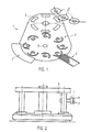
- FIG. 1 a schematic representation of an exemplary device 1 for applying a label to a container 6 is shown.
- a labeling unit for bottles In this example, it is in particular a labeling unit for bottles.
- other containers such as cans, conceivable.
- the exemplary apparatus 1 comprises a plurality of pallets 3, which may also be referred to as adhesive pallets, which are connected to a transport device which allows rotation about the axis A.
- the pallets 3 are part of a pallet rotary.
- the pallets 3 are guided past a label providing device 2 sequentially.
- the label providing device 2 may be, for example, a magazine in which the labels are kept stacked for transfer.
- the pallets 3 have an adhesive surface area. This surface area is provided with an adhesive such as cold glue and then brought into contact with a label from the label providing device 2. As a result, the label adheres to the adhesive surface area of the pallet 3. At least part of the adhesive is thereby transferred to the contact surface of the label.
- a heater 4 is provided which maintains the temperature of the adhesive on the pallet surface at a certain level. At this heater 4, the pallets 3 are passed during operation.
- a cooling device may also be provided.
- a cooling device may be arranged on a line between the glue pump and the labeling unit.
- quick-release couplings can be used for the arrangement. Especially in hot countries such Leimkühlung may be necessary.
- the temperature of the glue can be adjustable in particular between 18 ° C and 28 ° C.
- a provided with a label pallet 3 is moved and coincides with a gripper 5 of a gripper cylinder together.
- This gripper 5 accepts the arranged on the pallet 3 label and then brings it to one of the bottles 6, which are passed on a turntable on the labeling.
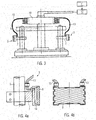
- FIG. 2 shows the pallet rotor in a side view, with the sake of clarity, only one of the pallets 3 is shown.
- the pallets 3 are connected to pallet shafts 9, whereby they are formed pivotable about a vertical axis.
- the pallets 3 comprise a pallet body 7 and an adhesive element 8 connected thereto.
- the area of the surface which can be provided with an adhesive and / or solvent and on which the label is placed is arranged on the front side of the adhesive element 8. However, the adhesive supply takes place via another side of the adhesive element 8.
- the adhesive element 8 can be detachably or permanently connected to the pallet body 7.
- the adhesive element 8 may be positively connected to the pallet body 7.
- the adhesive element 8 is made of a porous material, in particular a sintered material.
- the adhesive member 8 may also comprise a membrane permitting adhesive transport from the back of the adhesive member 8 to the front of the adhesive member 8 on which the surface area to be provided with the adhesive is disposed.
- a supply of the adhesive would also be conceivable via another side of the adhesive element 8 as its back.
- the adhesive could be supplied over the top of the adhesive element 8.
- the adhesive element 8 can be arranged as an insert in a recess of the pallet body 7.
- the adhesive element 8 may in particular be detachably connected to the pallet body 7.
- the adhesive such as hot glue
- the adhesive container 11 may be heated.
- cold glue can also be used.
- a temperature of about 25 ° C to 35 ° C is advantageous.
- the adhesive container 11 may, for example, a glue delivery as in the DE 10 2011 003 060.3 include or correspond to such.
- a required amount of glue is passed to a rotary distributor 10, which in turn passes the predetermined amount of adhesive via a feed line 13 to the respective pallet 3.
- the feed line 13 can also extend at least partially within the pallet shaft 9 and / or partially within the adhesive body 7. This alternative is in FIG. 3 indicated by a dashed line.
- a dosing unit 12 for example, a mechanical piston pump, a series pump or an electronic pump that allows a change in the amount of glue on the change in volume or pressure can be used.
- FIG. 4a shows a side view of an exemplary pallet 3, which is connected to a pallet shaft 9. With the pallet body 7, an adhesive element 8 is connected in the form of an insert.
- a reservoir 14 is arranged between the adhesive element 8 and the pallet body 7.
- This reservoir 14 corresponds to a cavity between the adhesive element 8 and the pallet body 7. In this cavity can be introduced via the supply line 13 adhesive.
- the adhesive reservoir 14 directly adjoins the adhesive element 8.
- the adhesive from the reservoir 14 becomes the front side of the adhesive element 8, on which a surface area which can be provided with an adhesive and / or solvent is arranged. In this case, the adhesive supply thus takes place via the rear side of the adhesive element 8.
- FIG. 4b shows a further side view of the exemplary pallet 3.
- the front of the adhesive element 8 is shown.
- a surface area which can be provided with an adhesive and / or solvent is arranged, on which a label, in particular a label, can be temporarily arranged in order to transfer an adhesive to the label and to transport the label further, so that it then passes over a gripping device can be applied to a container.
- the adhesive element 8 may in particular be a sintered material.
- the mean pore diameter can be between 15 .mu.m and 40 .mu.m.
- the porosity can be between 50% and 100%.
- a possible sintered material is available, for example, under the name "Metapor”.
- the pallet 3 can also comprise a heating element (not shown here), for example a UV emitter and / or a heating element operating via induction.
- a heating element for example a UV emitter and / or a heating element operating via induction.
- the temperature, in particular of the adhesive reservoir 14 can be maintained at a predetermined temperature value or temperature range, for example between 25 and 35 ° C.
- It can also be switched on a second circuit via a valve, via which a cleaning liquid, for example, is introduced in production breaks in the adhesive reservoir. Thereby, a cleaning of the adhesive element 8, in particular the pores of the adhesive element 8, can be achieved.
- the supply lines 13 shown may be provided for supplying adhesive and / or solvent, while the other supply line 13 serves for supplying a cleaning liquid.
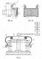
- FIGS. 5a and 5b are side views of another exemplary pallet 3, which is connected to a pallet shaft 9 shown.
- an adhesive element 8 is connected to the pallet body 7 in the form of an insert.
- the adhesive element 8 in this example obliquely upwardly extending holes 15. With these holes 15 centrifugal forces within the pallet 3 can be taken into account.
- the adhesive element 8 may be formed as described above, so in particular consist of a porous material.
- FIG. 6 shows a portion of another exemplary apparatus for applying a label to a container.
- Compressed air can be introduced from the compressed air source 55 into the rotary distributor 10 via the pressure reducer.
- the compressed air can be brought by the pressure reducer, for example, from a pressure of 2.5 bar to a pressure of 0.2 bar.
- the compressed air can then be passed to the pallet 3, where it can be used for example for removing label residues on the adhesive element.
- compressed air nozzles 26 include, in the compressed air via a channel 16 compressed air can be passed.
- the compressed air line 25 can also open directly into a compressed air nozzle.
- the compressed air outlets 26a of the compressed-air nozzles 26 can be arranged in particular along one side of the front side of the adhesive element 8, in particular along one of the transverse sides. This allows possible label residues to be blown off.
- the compressed air can be used before or after cleaning the pallet with a cleaning fluid and / or a rinse with fresh water or service water.
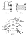
- FIG. 8 shows a schematic representation of another exemplary device 1 for applying a label to a container 6.
- this exemplary device 1 comprises a cleaning device 115.
- the exemplary cleaning device 115 comprises a spray nozzle 105, on which the pallets 3 are guided past the operation of the device 1.
- a cleaning liquid on the pallet 3, in particular on the adhesive element sprayed to remove, for example, adhesive or solvent residues.
- Such a cleaning can be carried out, for example, before the device is put into operation and / or at periodic time intervals.
- a compressed air nozzle 125a with the compressed air on the pallet 3, in particular on the adhesive element, can be blown.
- This external compressed air nozzle 125a may alternatively or in addition to the in FIGS. 7a and 7b be shown compressed air nozzles of the pallets.
- the cleaning device 115 also includes a brush roller 130b.
- This can be manually or automatically, especially pneumatic, delivered.
- the Brush roll 130 b are brought into a position in which they can mechanically clean the passing pallets 3.
- contaminated cleaning liquid can be collected and then sent for disposal or recycling.
- the elements of the cleaning device 115 described herein may be provided alone or in any combination with each other.
- FIG. 9 is a side view of part of an exemplary apparatus for applying a label to a container.
- a pallet runner is as in FIG. 2 shown.
- elements of a cleaning device are shown.
- the cleaning device comprises a cleaning liquid container 100. Cleaning liquid can be conducted from the cleaning liquid container 100 to a spray nozzle 105 via a pump 110. With the spray nozzle 105, the cleaning liquid can be sprayed onto the adhesive element 8 of the pallets 3, which are guided past the spray nozzle 105.
- the cleaning device also comprises a brush body 130a, which can be manually or automatically, in particular pneumatically, delivered to mechanically clean the pallets 3 passed by.
- a brush body 130a which can be manually or automatically, in particular pneumatically, delivered to mechanically clean the pallets 3 passed by.
- Another spray nozzle 106 may also spray cleaning fluid onto the brush body 130a and / or onto the pallet 3.
- a collecting trough 120 can be used to collect used cleaning liquid. Via a filter 17 and a return line 18, the used cleaning liquid can be supplied to the cleaning liquid container 100 again.
- the device can be rinsed with fresh water or service water at a temperature of 40 ° C to 60 ° C.
- the fresh water or service water can be switched on via a hand lever valve.
Landscapes
- Labeling Devices (AREA)
Applications Claiming Priority (1)
| Application Number | Priority Date | Filing Date | Title |
|---|---|---|---|
| DE102011082449A DE102011082449A1 (de) | 2011-09-09 | 2011-09-09 | Vorrichtung zum Aufbringen eines Etiketts auf einen Behälter |
Publications (2)
| Publication Number | Publication Date |
|---|---|
| EP2567902A1 true EP2567902A1 (fr) | 2013-03-13 |
| EP2567902B1 EP2567902B1 (fr) | 2015-02-18 |
Family
ID=46168255
Family Applications (1)
| Application Number | Title | Priority Date | Filing Date |
|---|---|---|---|
| EP20120169291 Not-in-force EP2567902B1 (fr) | 2011-09-09 | 2012-05-24 | Dispositif d'application d'une étiquette sur un récipient |
Country Status (3)
| Country | Link |
|---|---|
| EP (1) | EP2567902B1 (fr) |
| CN (1) | CN102991782B (fr) |
| DE (1) | DE102011082449A1 (fr) |
Cited By (3)
| Publication number | Priority date | Publication date | Assignee | Title |
|---|---|---|---|---|
| CN104417792A (zh) * | 2013-09-11 | 2015-03-18 | 克罗内斯股份公司 | 将灌装产品计量注入待灌装的容器的装置 |
| WO2017001073A1 (fr) * | 2015-06-30 | 2017-01-05 | Krones Ag | Dispositif et procédé d'étiquetage de récipients |
| EP3272663A1 (fr) * | 2016-07-22 | 2018-01-24 | Sidel Participations | Appareil d'étiquetage pour étiqueter des récipients et procédé pour faire fonctionner un tel appareil d'étiquetage |
Families Citing this family (4)
| Publication number | Priority date | Publication date | Assignee | Title |
|---|---|---|---|---|
| DE102013212136A1 (de) * | 2013-06-25 | 2015-01-08 | Krones Ag | System und Verfahren zum Reinigen von rotierbaren Elementen eines Etikettieraggregats |
| DE102014226937A1 (de) * | 2014-12-23 | 2016-06-23 | Krones Ag | Vorrichtung und Verfahren zum Etikettieren mit Etiketten mit aktivierbarem Kleber |
| DE102015212140A1 (de) * | 2015-06-30 | 2017-01-05 | Krones Ag | Vorrichtung und Verfahren zum Etikettieren von Behältern |
| DE202018102739U1 (de) * | 2018-05-16 | 2019-08-19 | Krones Ag | Etikettiervorrichtung mit Reinigungsvorrichtung für Etikettentransfermittel |
Citations (12)
| Publication number | Priority date | Publication date | Assignee | Title |
|---|---|---|---|---|
| DE170429C (fr) * | ||||
| GB638819A (en) * | 1948-07-15 | 1950-06-14 | Arthur Leslie Flower | Improvements in or relating to machines for labelling bottles and other containers |
| DE1073377B (de) * | 1960-01-14 | Hermann Kronseder, Neutraubling (Obpf.) | Beleimungsvorrichtung bei Etikettiermaschinen | |
| FR1377511A (fr) * | 1963-09-25 | 1964-11-06 | Chelle Ets | Perfectionnement apporté aux dispositifs à encoller et leurs applications |
| DE1187180B (de) * | 1963-05-21 | 1965-02-11 | Jagenberg Werke Ag | Leimauftragsvorrichtung fuer Etikettiermaschinen od. dgl. |
| DE2412002A1 (de) * | 1973-10-18 | 1975-09-18 | Kronseder Hermann | Verfahren und vorrichtung zum ausstatten von aufrechtstehend gefoerderten flaschen mit einer spitzstanniolierung |
| DE3022040A1 (de) * | 1980-06-12 | 1982-03-11 | Jagenberg-Werke AG, 4000 Düsseldorf | Verfahren zum vorbereiten der betriebsbereitschaftsstellung einer etikettierstation einer etikettiermaschine |
| DE3542848A1 (de) | 1985-12-04 | 1987-06-11 | Kronseder Maschf Krones | Beheizbare pumpe fuer zaehfluessige medien, insbesondere klebstoff |
| DE29519876U1 (de) | 1995-12-15 | 1996-02-08 | Privatbrauerei Erdinger Weißbräu Werner Brombach GmbH, 85435 Erding | Zentrale Leimversorgung |
| DE10045960A1 (de) | 1999-09-29 | 2001-04-05 | Oliver Timmer | Leimpumpe mit getrenntem Flüssigkeits- und Antriebsbereich |
| DE102006021056A1 (de) * | 2005-12-23 | 2007-06-28 | Töpfer Kulmbach GmbH | Verfahren zum Aufbringen eines Etikettes und Etikettieranlage hierzu |
| WO2009036869A1 (fr) | 2007-09-12 | 2009-03-26 | Khs Ag | Alimentation centralisée en colle pour des machines à étiqueter |
Family Cites Families (11)
| Publication number | Priority date | Publication date | Assignee | Title |
|---|---|---|---|---|
| GB335237A (en) * | 1929-06-13 | 1930-09-15 | Arthur Leslie Flower | Means for applying adhesive to labels |
| DE659385C (de) * | 1935-10-17 | 1938-05-04 | Jagenberg Werke Ag | Verfahren und Vorrichtung zum Beleimen von Werkstuecken |
| DE1772955U (de) * | 1958-07-08 | 1958-08-21 | Hermann Kronseder | Beleimungs- und etikettiervorrichtung. |
| DE1239615B (de) * | 1963-04-13 | 1967-04-27 | Jagenberg Werke Ag | Etikettiermaschine fuer Flaschen od. dgl. |
| US4369214A (en) * | 1980-05-14 | 1983-01-18 | Jagenberg Werke Ag | Process and apparatus for preventing hardening of glue on inactive bottle labeling machine |
| DE8400995U1 (de) * | 1984-01-14 | 1984-04-26 | Anker-Maschinenbau GmbH & Co, 2000 Hamburg | Leimsegment fuer etikettiermaschinen |
| US4662965A (en) * | 1985-12-18 | 1987-05-05 | Owens-Illinois, Inc. | Adhering heat sensitive labels to containers with hot melt adhesives |
| DE4419578B4 (de) * | 1994-06-03 | 2006-08-31 | Khs Eti-Tec Maschinenbau Gmbh | Etikettierstation |
| WO1998036974A1 (fr) * | 1997-02-25 | 1998-08-27 | Double J Consulting & Design, Inc. | Poste d'encollage et etiqueteuse |
| DE102006026618A1 (de) * | 2006-09-02 | 2008-03-13 | Khs Ag | Verfahren zum lagegenauen Aufbringen von Etiketten sowie Etikettiermaschine |
| DE102011003060A1 (de) | 2011-01-24 | 2012-07-26 | Krones Aktiengesellschaft | Leimzuführeinrichtung und Etikettiermaschine |
-
2011
- 2011-09-09 DE DE102011082449A patent/DE102011082449A1/de not_active Withdrawn
-
2012
- 2012-05-24 EP EP20120169291 patent/EP2567902B1/fr not_active Not-in-force
- 2012-09-10 CN CN201210333385.4A patent/CN102991782B/zh not_active Expired - Fee Related
Patent Citations (12)
| Publication number | Priority date | Publication date | Assignee | Title |
|---|---|---|---|---|
| DE170429C (fr) * | ||||
| DE1073377B (de) * | 1960-01-14 | Hermann Kronseder, Neutraubling (Obpf.) | Beleimungsvorrichtung bei Etikettiermaschinen | |
| GB638819A (en) * | 1948-07-15 | 1950-06-14 | Arthur Leslie Flower | Improvements in or relating to machines for labelling bottles and other containers |
| DE1187180B (de) * | 1963-05-21 | 1965-02-11 | Jagenberg Werke Ag | Leimauftragsvorrichtung fuer Etikettiermaschinen od. dgl. |
| FR1377511A (fr) * | 1963-09-25 | 1964-11-06 | Chelle Ets | Perfectionnement apporté aux dispositifs à encoller et leurs applications |
| DE2412002A1 (de) * | 1973-10-18 | 1975-09-18 | Kronseder Hermann | Verfahren und vorrichtung zum ausstatten von aufrechtstehend gefoerderten flaschen mit einer spitzstanniolierung |
| DE3022040A1 (de) * | 1980-06-12 | 1982-03-11 | Jagenberg-Werke AG, 4000 Düsseldorf | Verfahren zum vorbereiten der betriebsbereitschaftsstellung einer etikettierstation einer etikettiermaschine |
| DE3542848A1 (de) | 1985-12-04 | 1987-06-11 | Kronseder Maschf Krones | Beheizbare pumpe fuer zaehfluessige medien, insbesondere klebstoff |
| DE29519876U1 (de) | 1995-12-15 | 1996-02-08 | Privatbrauerei Erdinger Weißbräu Werner Brombach GmbH, 85435 Erding | Zentrale Leimversorgung |
| DE10045960A1 (de) | 1999-09-29 | 2001-04-05 | Oliver Timmer | Leimpumpe mit getrenntem Flüssigkeits- und Antriebsbereich |
| DE102006021056A1 (de) * | 2005-12-23 | 2007-06-28 | Töpfer Kulmbach GmbH | Verfahren zum Aufbringen eines Etikettes und Etikettieranlage hierzu |
| WO2009036869A1 (fr) | 2007-09-12 | 2009-03-26 | Khs Ag | Alimentation centralisée en colle pour des machines à étiqueter |
Cited By (6)
| Publication number | Priority date | Publication date | Assignee | Title |
|---|---|---|---|---|
| CN104417792A (zh) * | 2013-09-11 | 2015-03-18 | 克罗内斯股份公司 | 将灌装产品计量注入待灌装的容器的装置 |
| DE102013109968A1 (de) * | 2013-09-11 | 2015-03-26 | Krones Ag | Vorrichtung zum Dosieren eines Füllprodukts in einen zu befüllenden Behälter |
| EP2848580B1 (fr) * | 2013-09-11 | 2016-08-24 | Krones AG | Dispositif pour le dosage d'un produit dans un conteneur |
| WO2017001073A1 (fr) * | 2015-06-30 | 2017-01-05 | Krones Ag | Dispositif et procédé d'étiquetage de récipients |
| EP3272663A1 (fr) * | 2016-07-22 | 2018-01-24 | Sidel Participations | Appareil d'étiquetage pour étiqueter des récipients et procédé pour faire fonctionner un tel appareil d'étiquetage |
| US10894624B2 (en) | 2016-07-22 | 2021-01-19 | Sidel Participations | Labeling apparatus for labeling receptacles and a method for operating such a labeling apparatus |
Also Published As
| Publication number | Publication date |
|---|---|
| CN102991782B (zh) | 2016-05-18 |
| CN102991782A (zh) | 2013-03-27 |
| EP2567902B1 (fr) | 2015-02-18 |
| DE102011082449A1 (de) | 2013-03-14 |
Similar Documents
| Publication | Publication Date | Title |
|---|---|---|
| EP2567902B1 (fr) | Dispositif d'application d'une étiquette sur un récipient | |
| EP3317189B1 (fr) | Dispositif et procédé pour étiqueter des récipients | |
| EP3317192B1 (fr) | Rouleau d'encollage avec zone de collage limité | |
| EP2862718B1 (fr) | Machine de traitement de récipients destinée à l'impression de récipients | |
| EP3037357B1 (fr) | Dispositif et procede destines a l'etiquetage d'etiquettes adhesives pouvant etre activees | |
| EP2185425B1 (fr) | Dispositif et procédé d'étiquetage d'objets, en particulier de récipients pour liquide | |
| EP2072407B1 (fr) | Machine d'étiquetage | |
| EP3044103B1 (fr) | Dispositif pour le nettoyage d'un rouleau d'encollage d'une unité d'étiquetage | |
| EP3237290B1 (fr) | Dispositif et procede pour l'etiquetage des paquets seuls | |
| WO2014184126A1 (fr) | Machine d'impression | |
| EP2878382B1 (fr) | Procédé et dispositif d'application d'un produit coulant | |
| WO2017001072A1 (fr) | Dispositif et procédé d'application de colle sans élément de retour | |
| WO2011128439A1 (fr) | Système d'application pour milieux liquides | |
| EP0499818A1 (fr) | Procédé et dispositif pour la pose d'étiquettes sur des récipients | |
| WO2009071237A1 (fr) | Procédé d'étiquetage de récipients et poste d'étiquetage | |
| DE202012003268U1 (de) | Vorrichtung zur Handhabung von Etiketten | |
| EP3450183B1 (fr) | Machine et procédé d'impression directe destinés à l'impression de récipients par impression directe | |
| DE102015212143A1 (de) | Vorrichtung und Verfahren zum Etikettieren von Behältern | |
| DE69728451T2 (de) | Verfahren zum kühlen eines beschichteten rohres | |
| DE102010017295B3 (de) | Zuführvorrichtung für schmelzbares Fluid und Verfahren zum Zuführen eines schmelzbaren Fluids | |
| DE10349231B4 (de) | Vorrichtung zum Entetikettieren und Reinigen von Fässern | |
| EP0977688B1 (fr) | Dispositif d'application ainsi que procede d'application pour etiquettes sans support | |
| EP0405387B1 (fr) | Procédé et dispositif pour presser des ébauches en verre creuses | |
| EP0558010A1 (fr) | Procédé et dispositif pour imprimer des matériaux en bande | |
| EP2995454B1 (fr) | Dispositif de préparation d'encre sur une forme d'une unité d'impression |
Legal Events
| Date | Code | Title | Description |
|---|---|---|---|
| PUAI | Public reference made under article 153(3) epc to a published international application that has entered the european phase |
Free format text: ORIGINAL CODE: 0009012 |
|
| AK | Designated contracting states |
Kind code of ref document: A1 Designated state(s): AL AT BE BG CH CY CZ DE DK EE ES FI FR GB GR HR HU IE IS IT LI LT LU LV MC MK MT NL NO PL PT RO RS SE SI SK SM TR |
|
| AX | Request for extension of the european patent |
Extension state: BA ME |
|
| 17P | Request for examination filed |
Effective date: 20130809 |
|
| RBV | Designated contracting states (corrected) |
Designated state(s): AL AT BE BG CH CY CZ DE DK EE ES FI FR GB GR HR HU IE IS IT LI LT LU LV MC MK MT NL NO PL PT RO RS SE SI SK SM TR |
|
| 17Q | First examination report despatched |
Effective date: 20140123 |
|
| GRAP | Despatch of communication of intention to grant a patent |
Free format text: ORIGINAL CODE: EPIDOSNIGR1 |
|
| INTG | Intention to grant announced |
Effective date: 20141007 |
|
| GRAS | Grant fee paid |
Free format text: ORIGINAL CODE: EPIDOSNIGR3 |
|
| GRAA | (expected) grant |
Free format text: ORIGINAL CODE: 0009210 |
|
| AK | Designated contracting states |
Kind code of ref document: B1 Designated state(s): AL AT BE BG CH CY CZ DE DK EE ES FI FR GB GR HR HU IE IS IT LI LT LU LV MC MK MT NL NO PL PT RO RS SE SI SK SM TR |
|
| REG | Reference to a national code |
Ref country code: GB Ref legal event code: FG4D Free format text: NOT ENGLISH |
|
| REG | Reference to a national code |
Ref country code: CH Ref legal event code: EP |
|
| REG | Reference to a national code |
Ref country code: AT Ref legal event code: REF Ref document number: 710562 Country of ref document: AT Kind code of ref document: T Effective date: 20150315 |
|
| REG | Reference to a national code |
Ref country code: IE Ref legal event code: FG4D Free format text: LANGUAGE OF EP DOCUMENT: GERMAN |
|
| REG | Reference to a national code |
Ref country code: DE Ref legal event code: R096 Ref document number: 502012002277 Country of ref document: DE Effective date: 20150402 |
|
| REG | Reference to a national code |
Ref country code: NL Ref legal event code: VDEP Effective date: 20150218 |
|
| REG | Reference to a national code |
Ref country code: LT Ref legal event code: MG4D |
|
| PG25 | Lapsed in a contracting state [announced via postgrant information from national office to epo] |
Ref country code: SE Free format text: LAPSE BECAUSE OF FAILURE TO SUBMIT A TRANSLATION OF THE DESCRIPTION OR TO PAY THE FEE WITHIN THE PRESCRIBED TIME-LIMIT Effective date: 20150218 Ref country code: LT Free format text: LAPSE BECAUSE OF FAILURE TO SUBMIT A TRANSLATION OF THE DESCRIPTION OR TO PAY THE FEE WITHIN THE PRESCRIBED TIME-LIMIT Effective date: 20150218 Ref country code: ES Free format text: LAPSE BECAUSE OF FAILURE TO SUBMIT A TRANSLATION OF THE DESCRIPTION OR TO PAY THE FEE WITHIN THE PRESCRIBED TIME-LIMIT Effective date: 20150218 Ref country code: FI Free format text: LAPSE BECAUSE OF FAILURE TO SUBMIT A TRANSLATION OF THE DESCRIPTION OR TO PAY THE FEE WITHIN THE PRESCRIBED TIME-LIMIT Effective date: 20150218 Ref country code: NO Free format text: LAPSE BECAUSE OF FAILURE TO SUBMIT A TRANSLATION OF THE DESCRIPTION OR TO PAY THE FEE WITHIN THE PRESCRIBED TIME-LIMIT Effective date: 20150518 Ref country code: HR Free format text: LAPSE BECAUSE OF FAILURE TO SUBMIT A TRANSLATION OF THE DESCRIPTION OR TO PAY THE FEE WITHIN THE PRESCRIBED TIME-LIMIT Effective date: 20150218 |
|
| PG25 | Lapsed in a contracting state [announced via postgrant information from national office to epo] |
Ref country code: LV Free format text: LAPSE BECAUSE OF FAILURE TO SUBMIT A TRANSLATION OF THE DESCRIPTION OR TO PAY THE FEE WITHIN THE PRESCRIBED TIME-LIMIT Effective date: 20150218 Ref country code: GR Free format text: LAPSE BECAUSE OF FAILURE TO SUBMIT A TRANSLATION OF THE DESCRIPTION OR TO PAY THE FEE WITHIN THE PRESCRIBED TIME-LIMIT Effective date: 20150519 Ref country code: IS Free format text: LAPSE BECAUSE OF FAILURE TO SUBMIT A TRANSLATION OF THE DESCRIPTION OR TO PAY THE FEE WITHIN THE PRESCRIBED TIME-LIMIT Effective date: 20150618 Ref country code: RS Free format text: LAPSE BECAUSE OF FAILURE TO SUBMIT A TRANSLATION OF THE DESCRIPTION OR TO PAY THE FEE WITHIN THE PRESCRIBED TIME-LIMIT Effective date: 20150218 Ref country code: NL Free format text: LAPSE BECAUSE OF FAILURE TO SUBMIT A TRANSLATION OF THE DESCRIPTION OR TO PAY THE FEE WITHIN THE PRESCRIBED TIME-LIMIT Effective date: 20150218 |
|
| PG25 | Lapsed in a contracting state [announced via postgrant information from national office to epo] |
Ref country code: DK Free format text: LAPSE BECAUSE OF FAILURE TO SUBMIT A TRANSLATION OF THE DESCRIPTION OR TO PAY THE FEE WITHIN THE PRESCRIBED TIME-LIMIT Effective date: 20150218 Ref country code: EE Free format text: LAPSE BECAUSE OF FAILURE TO SUBMIT A TRANSLATION OF THE DESCRIPTION OR TO PAY THE FEE WITHIN THE PRESCRIBED TIME-LIMIT Effective date: 20150218 Ref country code: RO Free format text: LAPSE BECAUSE OF FAILURE TO SUBMIT A TRANSLATION OF THE DESCRIPTION OR TO PAY THE FEE WITHIN THE PRESCRIBED TIME-LIMIT Effective date: 20150218 Ref country code: CZ Free format text: LAPSE BECAUSE OF FAILURE TO SUBMIT A TRANSLATION OF THE DESCRIPTION OR TO PAY THE FEE WITHIN THE PRESCRIBED TIME-LIMIT Effective date: 20150218 Ref country code: SK Free format text: LAPSE BECAUSE OF FAILURE TO SUBMIT A TRANSLATION OF THE DESCRIPTION OR TO PAY THE FEE WITHIN THE PRESCRIBED TIME-LIMIT Effective date: 20150218 |
|
| REG | Reference to a national code |
Ref country code: DE Ref legal event code: R097 Ref document number: 502012002277 Country of ref document: DE |
|
| PG25 | Lapsed in a contracting state [announced via postgrant information from national office to epo] |
Ref country code: PL Free format text: LAPSE BECAUSE OF FAILURE TO SUBMIT A TRANSLATION OF THE DESCRIPTION OR TO PAY THE FEE WITHIN THE PRESCRIBED TIME-LIMIT Effective date: 20150218 |
|
| PLBE | No opposition filed within time limit |
Free format text: ORIGINAL CODE: 0009261 |
|
| STAA | Information on the status of an ep patent application or granted ep patent |
Free format text: STATUS: NO OPPOSITION FILED WITHIN TIME LIMIT |
|
| REG | Reference to a national code |
Ref country code: CH Ref legal event code: PL |
|
| 26N | No opposition filed |
Effective date: 20151119 |
|
| PG25 | Lapsed in a contracting state [announced via postgrant information from national office to epo] |
Ref country code: LU Free format text: LAPSE BECAUSE OF FAILURE TO SUBMIT A TRANSLATION OF THE DESCRIPTION OR TO PAY THE FEE WITHIN THE PRESCRIBED TIME-LIMIT Effective date: 20150524 Ref country code: CH Free format text: LAPSE BECAUSE OF NON-PAYMENT OF DUE FEES Effective date: 20150531 Ref country code: LI Free format text: LAPSE BECAUSE OF NON-PAYMENT OF DUE FEES Effective date: 20150531 Ref country code: MC Free format text: LAPSE BECAUSE OF FAILURE TO SUBMIT A TRANSLATION OF THE DESCRIPTION OR TO PAY THE FEE WITHIN THE PRESCRIBED TIME-LIMIT Effective date: 20150218 |
|
| REG | Reference to a national code |
Ref country code: IE Ref legal event code: MM4A |
|
| PG25 | Lapsed in a contracting state [announced via postgrant information from national office to epo] |
Ref country code: SI Free format text: LAPSE BECAUSE OF FAILURE TO SUBMIT A TRANSLATION OF THE DESCRIPTION OR TO PAY THE FEE WITHIN THE PRESCRIBED TIME-LIMIT Effective date: 20150218 |
|
| REG | Reference to a national code |
Ref country code: FR Ref legal event code: PLFP Year of fee payment: 5 |
|
| PG25 | Lapsed in a contracting state [announced via postgrant information from national office to epo] |
Ref country code: IE Free format text: LAPSE BECAUSE OF NON-PAYMENT OF DUE FEES Effective date: 20150524 |
|
| PG25 | Lapsed in a contracting state [announced via postgrant information from national office to epo] |
Ref country code: MT Free format text: LAPSE BECAUSE OF FAILURE TO SUBMIT A TRANSLATION OF THE DESCRIPTION OR TO PAY THE FEE WITHIN THE PRESCRIBED TIME-LIMIT Effective date: 20150218 |
|
| GBPC | Gb: european patent ceased through non-payment of renewal fee |
Effective date: 20160524 |
|
| REG | Reference to a national code |
Ref country code: FR Ref legal event code: PLFP Year of fee payment: 6 |
|
| PG25 | Lapsed in a contracting state [announced via postgrant information from national office to epo] |
Ref country code: GB Free format text: LAPSE BECAUSE OF NON-PAYMENT OF DUE FEES Effective date: 20160524 Ref country code: BG Free format text: LAPSE BECAUSE OF FAILURE TO SUBMIT A TRANSLATION OF THE DESCRIPTION OR TO PAY THE FEE WITHIN THE PRESCRIBED TIME-LIMIT Effective date: 20150218 Ref country code: SM Free format text: LAPSE BECAUSE OF FAILURE TO SUBMIT A TRANSLATION OF THE DESCRIPTION OR TO PAY THE FEE WITHIN THE PRESCRIBED TIME-LIMIT Effective date: 20150218 Ref country code: HU Free format text: LAPSE BECAUSE OF FAILURE TO SUBMIT A TRANSLATION OF THE DESCRIPTION OR TO PAY THE FEE WITHIN THE PRESCRIBED TIME-LIMIT; INVALID AB INITIO Effective date: 20120524 |
|
| PG25 | Lapsed in a contracting state [announced via postgrant information from national office to epo] |
Ref country code: CY Free format text: LAPSE BECAUSE OF FAILURE TO SUBMIT A TRANSLATION OF THE DESCRIPTION OR TO PAY THE FEE WITHIN THE PRESCRIBED TIME-LIMIT Effective date: 20150218 |
|
| PG25 | Lapsed in a contracting state [announced via postgrant information from national office to epo] |
Ref country code: BE Free format text: LAPSE BECAUSE OF NON-PAYMENT OF DUE FEES Effective date: 20150531 |
|
| PG25 | Lapsed in a contracting state [announced via postgrant information from national office to epo] |
Ref country code: TR Free format text: LAPSE BECAUSE OF FAILURE TO SUBMIT A TRANSLATION OF THE DESCRIPTION OR TO PAY THE FEE WITHIN THE PRESCRIBED TIME-LIMIT Effective date: 20150218 |
|
| REG | Reference to a national code |
Ref country code: FR Ref legal event code: PLFP Year of fee payment: 7 |
|
| PG25 | Lapsed in a contracting state [announced via postgrant information from national office to epo] |
Ref country code: PT Free format text: LAPSE BECAUSE OF FAILURE TO SUBMIT A TRANSLATION OF THE DESCRIPTION OR TO PAY THE FEE WITHIN THE PRESCRIBED TIME-LIMIT Effective date: 20150218 Ref country code: MK Free format text: LAPSE BECAUSE OF FAILURE TO SUBMIT A TRANSLATION OF THE DESCRIPTION OR TO PAY THE FEE WITHIN THE PRESCRIBED TIME-LIMIT Effective date: 20150218 |
|
| REG | Reference to a national code |
Ref country code: AT Ref legal event code: MM01 Ref document number: 710562 Country of ref document: AT Kind code of ref document: T Effective date: 20170524 |
|
| PG25 | Lapsed in a contracting state [announced via postgrant information from national office to epo] |
Ref country code: AT Free format text: LAPSE BECAUSE OF NON-PAYMENT OF DUE FEES Effective date: 20170524 |
|
| PG25 | Lapsed in a contracting state [announced via postgrant information from national office to epo] |
Ref country code: AL Free format text: LAPSE BECAUSE OF FAILURE TO SUBMIT A TRANSLATION OF THE DESCRIPTION OR TO PAY THE FEE WITHIN THE PRESCRIBED TIME-LIMIT Effective date: 20150218 |
|
| PGFP | Annual fee paid to national office [announced via postgrant information from national office to epo] |
Ref country code: FI Payment date: 20190522 Year of fee payment: 15 |
|
| PGFP | Annual fee paid to national office [announced via postgrant information from national office to epo] |
Ref country code: FR Payment date: 20190410 Year of fee payment: 8 |
|
| PG25 | Lapsed in a contracting state [announced via postgrant information from national office to epo] |
Ref country code: FR Free format text: LAPSE BECAUSE OF NON-PAYMENT OF DUE FEES Effective date: 20200531 |
|
| PG25 | Lapsed in a contracting state [announced via postgrant information from national office to epo] |
Ref country code: IT Free format text: LAPSE BECAUSE OF NON-PAYMENT OF DUE FEES Effective date: 20200524 |
|
| PGFP | Annual fee paid to national office [announced via postgrant information from national office to epo] |
Ref country code: DE Payment date: 20220329 Year of fee payment: 11 |
|
| REG | Reference to a national code |
Ref country code: DE Ref legal event code: R119 Ref document number: 502012002277 Country of ref document: DE |
|
| PG25 | Lapsed in a contracting state [announced via postgrant information from national office to epo] |
Ref country code: DE Free format text: LAPSE BECAUSE OF NON-PAYMENT OF DUE FEES Effective date: 20231201 |