EP2567928B1 - Capteur, dispositif de sécurisation et dispositif d'ascenseur - Google Patents
Capteur, dispositif de sécurisation et dispositif d'ascenseur Download PDFInfo
- Publication number
- EP2567928B1 EP2567928B1 EP20110008340 EP11008340A EP2567928B1 EP 2567928 B1 EP2567928 B1 EP 2567928B1 EP 20110008340 EP20110008340 EP 20110008340 EP 11008340 A EP11008340 A EP 11008340A EP 2567928 B1 EP2567928 B1 EP 2567928B1
- Authority
- EP
- European Patent Office
- Prior art keywords
- sensor
- receiver
- contact
- contact bridge
- sensor according
- Prior art date
- Legal status (The legal status is an assumption and is not a legal conclusion. Google has not performed a legal analysis and makes no representation as to the accuracy of the status listed.)
- Active
Links
Images




Classifications
-
- B—PERFORMING OPERATIONS; TRANSPORTING
- B66—HOISTING; LIFTING; HAULING
- B66B—ELEVATORS; ESCALATORS OR MOVING WALKWAYS
- B66B13/00—Doors, gates, or other apparatus controlling access to, or exit from, cages or lift well landings
- B66B13/22—Operation of door or gate contacts
-
- H—ELECTRICITY
- H03—ELECTRONIC CIRCUITRY
- H03K—PULSE TECHNIQUE
- H03K17/00—Electronic switching or gating, i.e. not by contact-making and –breaking
- H03K17/94—Electronic switching or gating, i.e. not by contact-making and –breaking characterised by the way in which the control signals are generated
- H03K17/965—Switches controlled by moving an element forming part of the switch
- H03K17/968—Switches controlled by moving an element forming part of the switch using opto-electronic devices
Definitions
- the invention relates to a sensor for safety devices for elevator devices according to the preamble of claim 1, a safety device for elevator devices according to the preamble of claim 15, a safety device for elevator device according to the preamble of claim 18.
- Out GB 876,371 is a sensor according to the preamble of claim 1 is known.
- the object of the invention is to propose a sensor, a safety device and an elevator device, in which the need for maintenance can be improved.
- an inventive sensor for Securing devices for elevator devices which can move a car via a drive, characterized in that the sensor is designed as an optical sensor comprising a transmitter for transmitting an optical signal and a receiver for receiving the optical signal. It is particularly advantageous for the sensor according to the invention that it can operate without contact, that is also wear-free. In addition, the sensor according to the invention thus has no or less voltage-carrying contact surfaces and is also safe to install. The sensor according to the invention can therefore replace a commercially available switch, a so-called interlock switch, from the prior art.
- the senor according to the invention allows that in contrast to an electromechanical switch no interruption of the circuit must be made.
- a defect can be avoided by the sensor according to the invention, the z. B. in electromechanical sensors and contacts by contact firing as a result of sparkover when opening or closing the electrical contacts and can eventually lead to loss of function. Consequently, the maintenance susceptibility can be improved by the sensor according to the invention.
- a contact bridge and a contact receiver for receiving the contact bridge are provided, which are arranged so that the closed state of the elevator door can be determined by connecting the contact person and contact bridge.
- the detection state of the sensor therefore depends on the approach of the contact bridge to the contact person.
- An elevator itself generally has on the one hand a cabin, which can be moved between individual floors or floors.
- the individual floors have each Manhole openings in the area of which the cabin can be moved to a holding position if it is to approach the corresponding floor. In this holding position access to the cabin is then possible.
- Elevator doors can be landing doors or cabin doors.
- the shaft doors are mounted or moved in the shaft opening in the shaft itself.
- the car doors in turn are attached to the cabin and stored mobile. Regularly a landing door is assigned to a car door, wherein both are arranged overlapping (at least partially overlapping) in the holding position. These are usually also at least substantially synchronously.
- the interruption device or interruption circuit can control the control unit, i. H. Control or regulation, the motor or the drive responsive, so that it stops the drive, it is also conceivable that the interruption device directly interrupts the power supply of the drive / motor.
- the corresponding sensor is thus designed to check whether the corresponding door of a lift or a shaft is open or closed and locked.
- this measure allows a mechanically very stable device.
- a sensor according to the invention can be designed so that the contact bridge is received with play or positively in the slot of the contact.
- the contact bridge is designed such that it comprises at least one transmission element for transmitting an optical signal.
- a so-called fail-safe circuit ie a fail-safe circuit can be achieved. Only when the contact bridge has reached a special position by corresponding connection with the contact person when closing the door, a corresponding release for the ride can be issued.
- the transmission element can namely be designed in such a way that the transmission of the optical signal takes place in a special way, which can only be manipulated very difficultly and which is not accidentally realized without further ado. If it were, for example, a mere photoelectric barrier, which would be interrupted when closing the door, this would mean that the drive would be released even if z. B. a corresponding object, a fly or the like interrupts the light barrier.
- the transmission element is a reflection surface, which then reflects the optical signal or the light and only then conducts to the corresponding receiver.
- the reflection surface may, for example, be arranged in a notch in the contact bridge.
- the transmission element is an optical medium. It is conceivable, for example, that the refraction of light is used in the transition from the air into this optical medium and the light beam is thus directed in a certain direction, so that only then is passed either on the receiver or just not on the receiver.
- optical medium may further be provided in one embodiment of the invention, a light guide.
- the optical signal is transmitted when its light is coupled into the optical fiber, propagated through the optical fiber and passed through the optical fiber in the receiver.
- the transmitter is particularly advantageous to design the transmitter as a light-emitting diode and / or the receiver as a photodiode.
- These are particularly inexpensive standard electronic components; In particular, this can save costs.
- a separating element in particular a separating web for the optical separation of transmitter and receiver, can additionally be provided. This basically reduces the possibility of errors due to a misinterpretation of the signals.
- a diffuser can also be provided which spreads diffused light diffusely. It is also conceivable that the receiver is set to a certain threshold with respect to the intensity of the incident light in the detection, so that at a certain amount of stray light, which may fall into the receiver, not yet a corresponding sequence signal is triggered, which only then resolved should be when light falls in the receiver via the transmission element.
- an embodiment may be designed so that the probability of accidental reflection with which the signal from the transmitter and the receiver reaches the contact, is minimized.
- the signal from the transmitter can not be routed to the receiver via a single reflection, ie a special optical path is necessary.
- the transmitter and the receiver are arranged so that the signal of the transmitter must be guided over at least two reflections to the receiver.
- a combination of reflections and the coupling into a light guide so that the light is reflected and then has to propagate a certain distance through a light guide.
- a special coupling for example by a lens may be necessary.
- the senor is shielded in such a way that the reflection can practically not happen by chance. It is also possible to set the threshold in the receiver so high that only a corresponding reflection by a reflection unit causes a signal, whereby the threshold can be exceeded.
- the contact bridge is designed to guide the signal of the transmitter via 4 reflections to the receiver.
- the contact person comprises transmission elements for transmitting the optical signal, e.g. Reflective surfaces or optical media such as e.g. Light guide. It is conceivable that a portion of the propagation path of the optical signal from the transmitter to the receiver via a reflection surface or by an optical fiber in the contact takes place. It is also conceivable that by receiving the contact bridge of the optical fiber in the contact or in the contact bridge is shifted so that a transmission of the light is made possible.
- a connection can be made, in which the contactor comprises a shaft and the contact bridge comprises a tongue-shaped tab, which engages in connection of contact bridge and contact in the slot. It is also particularly advantageous that a corresponding coding can be made, that is, that the contact bridge, similar to a key, must be specially designed so that it can penetrate into the contact person. This can in particular increase the safety of this device, in particular if the contact-receiving shaft is designed so that no hand can penetrate.
- At least two transmission elements are provided, which are arranged one behind the other in the direction of movement of the contact bridge, which means that when locking the door, the contact bridge correspondingly dips into the contact and initially for the optical signal or the optical light beam of the Transmission elements (namely, the first in the direction of movement) is visible. When pushing further, the next transmission element is then visible, while the previous is pushed out of the optical path. It can thus offset in time several optical signals occur. Furthermore, it is conceivable to design an associated evaluation unit or electronic unit such that, for example, the occurrence of the corresponding signals is determined as a function of time. In addition, conclusions about the speed of locking can be determined. This also allows a conclusion on the functional and maintenance condition of the locking device of the door. Basically, moreover, the interlock, not the door closing is monitored. Depending on how the corresponding transmission elements are arranged or how many of the transmission elements are arranged, if appropriate, the precision of such a determination can be increased.
- the senor may comprise an electronic unit for evaluating the receiver, which is designed to interpret the evaluation of the receiver in one of the switching states and / or in an electrical signal.
- the electronics unit is designed to generate an electrical signal, depending on what the receiver detects.
- the change of a switching state can be done for example by generating an electrical signal in response to the detection of the receiver.
- the mechanical closing state is detected purely by optical means, this means that it is not absolutely necessary again to produce a mechanical contact or a mechanical opening state in order to obtain an electrical signal.
- the optical signal, the receiver such as a photodiode, turns on and thus a line state (in contrast to an interruption) can be achieved.
- the electronics unit can also be designed in addition to allow a connection to other electronics.
- it may also be designed to enable a connection to a bus.
- the lower maintenance susceptibility can be improved since mechanical contacts and sensor are essentially avoided. It is also particularly advantageous that only the penetration of the contact bridge into the contact receiver is necessary as a mechanical contact closure.
- the electronic unit is for communication with a switching unit, in particular for the transmission of switching states and / or identification signals.
- the switching unit is a component with which a line can be opened or closed by a switching operation, similar to a relay or contactor.
- the switching process is triggered when the sensors transmit a corresponding signal or corresponding information to the switching unit. It is particularly advantageous that the line between the switching unit and the sensor no longer has to be interrupted, as is the case for example regularly with a contactor / relay.
- the electronics unit can be arranged in particular in or on the contact, in which transmitter and receiver are arranged.
- the contact person may be arranged statically in the elevator device, for example, while the Contact bridge is disposed on a movable part and merely represents the "key" to enable the signal transmission in the contactor.
- the communication via a modulation of its own resistance of the sensor can be done.
- the voltage and / or the current intensity can be modulated in the circuit with the switching unit.
- This modulation then carries the information that is to be transferred in the communication.
- a circuit comprising series connected sensors and (also in series) a switching unit. If the resistance of a sensor is changed with sensors connected in series, the current intensity changes.
- a change in resistance causes the voltage to be increased to compensate for the resulting decrease in current initially caused by the lower resistance.
- the modulation can therefore be the carrier of the information.
- the changes in current or voltage are measurable and can be interpreted as information.
- the senor is intended for use in series connection.
- a series connection it is particularly advantageous if the sensor is a low Has volume resistance.
- the resistance of a sensor can be, for example, in the range of greater than 0 ohms to 100 ohms, in particular in the range of greater than 0 ohms to 20 ohms, preferably less than 10 ohms, in particular less than 5 ohms.
- a securing device for elevator devices which can move a car via a drive
- an interruption device for interrupting the drive having at least one sensor which can be switched between at least two switching states as a function of the closing state of the elevator door
- the interruption device for this purpose is formed, depending on the switching state of the at least one sensor to interrupt the drive and / or continue, characterized in that a sensor is used according to the invention.
- the interruption device is used to interrupt the drive, wherein the interruption depends on how the switching states of the corresponding sensor, that is, on whether all doors are actually locked.
- the interruption unit may, for example, also be designed as a switching unit which has a communication unit in order to be able to carry out a switching operation with a corresponding signal from the sensor.
- the ride can only be started or continued when all doors are locked. Accordingly, it is expedient if the corresponding sensors, which are each assigned to a door, are connected in series.
- an elevator device which comprises a safety device according to the invention.
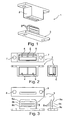
- FIG. 1 shows a sensor 1 with a contact 2 (shaft) and a contact bridge 3, wherein the contact bridge has reflection strips 9, which reflect light emitted by a transmitter of the contact 2 in the direction of a receiver of the contact 2.
- FIG. 2 again shows the corresponding contact 2 with a transmitter 4 and a receiver 5, between which a divider 6 is arranged, in front view, side view and top view.
- a divider 6 is arranged, in front view, side view and top view.
- the contactor 2 has additional electrical connections, via which the sensor 1 can be connected to the rest of the sensor device or to the safety circuit.
- FIG. 3 shows a contact bridge in different views in front view, side view and top view. These also include corresponding mounting aids 8.
- transmission elements 9 slots are incorporated in the contact bridge 3, each having reflection surfaces.
- the reflection units 9a, 9b, 9c there are three reflection units 9a, 9b, 9c, so that to some extent a dynamic contact detection is possible, since upon penetration of the contact bridge 3 in the contact 2 and in the optical light path first the reflection unit 9a, then the reflection unit 9b and finally 9c penetrate and thus a dynamic measurement of the signal in time dependence is possible.
- FIG. 4 shows a sensor 1 'with a contactor 2 (slot) and a contact bridge 3', wherein the contact bridge has a light guide; the light emitted by a transmitter of the contactor 2 passes into the light guide input 4 ', propagates through the light guide and leaves the light guide output 5' again, so that it reaches the receiver of the contactor 2.
- FIG. 5 again shows the corresponding contact 2, as he already too FIG. 2 has been described, which is also suitable for a sensor 1 'with light guide.
- FIG. 6 shows a contact bridge 3 'in different views, in front view, side view and top view. This also includes corresponding assembly aids 8.
- a transmission element L a light guide is incorporated into the contact bridge 3 ', through which the light signal emitted by the contact receiver can propagate. You can also see the light inlet 4 'and the light output 5'.
- FIG. 7 shows such a penetration of the contact bridge. 3 (with reflection strip) in the contactor 2, wherein in situation A, the contact bridge is not yet in communication with the contact 2.
- the reflection unit 9a has just penetrated in the region of the optical path and transmits the light path from the transmitter to the receiver.
- situation C the contact bridge 3 is just so that an interruption of the optical signal takes place, since the contact bridge 3 in height is just between the reflection units 9b and 9c and the optical path is thus interrupted.
- the contact bridge Only in situation D is the contact bridge, which is fully retracted into the contactor 2, in such a position that the optical path is not interrupted and the receiver 4 can pass light via the reflection element 9c into the detector / photodiode.
- the reflection units 9, and also other transmission units such as optical media can have different shapes and provide characteristic reflections or light transmissions, so that these can also be identified by means of the receiver or the electronics unit, if appropriate.
- FIG. 8 shows a similar view, in which the contact bridge 3 penetrates into the contact 2.
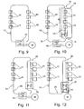
- FIG. 9 again shows a security device with multiple optical sensors 10, which are all connected in series. Furthermore, there are a number of other electromechanical opening switches 11 which can be used in any other way in conjunction with a lift. In addition, a voltage source 13 is present. All these switches or sensors 11 and 10 are connected in series and connected to a switching unit 12. This circuit of a series connection of the switches 11, the sensors 10 and the switching unit 12 forms a safety circuit. If one of the switches 11 is interrupted, the entire circuit is interrupted and the switching unit 12 switches off the motor M, which is the drive for the elevator car.
- the switches 11 may be opening switches of known type.
- the switching unit 12 Detects one of the sensors 10, that eg the elevator is not is properly locked, it sends a corresponding signal via the circuit that is received by the communication unit of the switching unit 12, so that they can turn off the motor M. Accordingly, the switching unit 12 partially takes over the function of your relay; In addition, switching operations of the switching unit but also dependent on signals from the sensors. The switching unit 12 thus not only reacts to line breaks.
- FIG. 10 shows a safety device with a safety device, namely a (second) safety circuit 14, with corresponding optical sensors 10.
- This safety circuit is connected via a switching unit 12 'with the first safety circuit 16, which in turn has further sensor 11.
- the switching unit 12 ' is similar to the switching unit 12 and has the same operation; This is in contrast to the switching unit 12 off FIG. 9 however, the voltage source is integrated with the switching unit 12 '.
- the first safety circuit 16 is a contactor / relay 15, which in turn off a drive M.
- the contactor 15 is merely designed to switch off the motor M in the event of a line interruption of the circuit 16. If one of the sensors 10 is interrupted optically interrupted, then the switching unit 12 'is interrupted and thus the line of the first safety circuit 16.
- the contactor 15 switches off the motor M.
- the sensors according to the invention are combined in a separate safety circuit 14 and connected via the switching unit 12 'to the original, first safety circuit 16.
- the safety circuit 16 may partially use the wiring of the original safety device.
- FIG. 10 is also shown how a retrofitting of a conventional device can be done by the original first safety circuit 16 is cut at the points U and the second safety circuit 14 with the switching unit 12 'is used accordingly. It must be fed then only a longer cable K.
- FIG. 11 shows a corresponding device in which instead of a second safety circuit as a backup device, a bus 20 is arranged.
- the corresponding sensors 21 have an electronics unit, which enable a connection to the corresponding bus 20.
- the bus is also connected to a switching unit 25, so when interrupting one of the optical sensor 21 this in turn sends a signal to the switching unit 25, which in turn interrupts the first safety circuit 26. With the contactor 15, the motor M is switched off due to the broken line of the safety circuit 26.
- the switching unit 25 may form the master in the bus while the sensors 21 are in slave configuration.
- FIG. 12 shows a similar device as FIG. 8 However, here the contactor 15 is additionally integrated into the switching unit 27, wherein the contactor shuts off the motor if necessary.
- FIG. 13 shows an exemplary circuit diagram 30 for a lift gem. the invention.
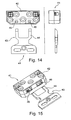
- FIG. 14 shows a sensor 41 in plan view and in a side view with a contact receiver 42 and a contact bridge 43, in which a light guide 44 is arranged.
- the contact bridge 43 is designed overall as a light guide 44, ie it consists of the corresponding optical medium.
- the contactor 42 includes a transmitter 45 and a receiver 46 for transmitting / receiving optical signals.
- the optical signal emitted by the transmitter 45 can, as soon as the contact receiver 42 has picked up the contact bridge 43, propagate through the light conductor 44 and thus reaches the receiver 46.
- the contact bridge 43 (or the light conductor 44) is U-shaped and grips, when inserted into the contactor 42, only with the two legs in the two slots of the contactor 42 a.
- the light guide 44 is accordingly also U-shaped.
- FIG. 15 again shows the sensor 41 in one perspective view.
- FIG. 16 shows a schematic representation of the communication in the safety circuit 14 between the controller 57 of the switching unit and the individual sensors 10 and their microcontroller microcontroller.
- the units 50, 51 each correspond to a sensor. With the reference numerals 52, 53 variable resistors are shown. Each sensor is assigned a variable resistor.
- the change of the resistance can take place in different ways: It is conceivable that resistances are connected in parallel to others, whereby the total resistance decreases accordingly. But it is also conceivable that circuit technology, for example by blocking individual transistors, the resistance is affected.
- the change in resistance can be optically influenced, e.g. by phototransistors, photodiodes, optocouplers o. ⁇ .
- the circuit includes constant current sources 54, 55, each of which is adapted to adjust its voltage as the resistance in the circuit changes so that a constant current flows.
- Change in resistance (communication: controller 57 to sensor 10) regulates the constant current source 54 to a constant current level so that the voltage measured across the voltmeter 56 changes.
- the current intensity can also be modulated, ie the voltage does not remain constant (communication: sensor to controller).
- the change in the voltage applied to the circuit can be determined by the voltmeter 58.
- the states of the individual sensors or other data of the sensors can be output via an output 60.
- the relay 59 is controlled according to the sensors.
- FIG. 16 is a switching unit 12 '' shown, such as in FIG. 9 as a switching unit 12 or in FIG. 10 is shown as switching unit 12 '.
- the switching unit 12 ' still comprises a voltage source.
- the switching unit 12 off FIG. 9 In particular, it also includes the function of a relay which can also switch off the motor M when the line is interrupted.
- the switching unit 12 is in FIG. 16 connected to a (second) safety circuit 14.
Landscapes
- Maintenance And Inspection Apparatuses For Elevators (AREA)
- Switches Operated By Changes In Physical Conditions (AREA)
- Electronic Switches (AREA)
- Push-Button Switches (AREA)
Claims (17)
- Capteur (1, 1', 10, 21, 41) pour des dispositifs de sécurité pour des dispositifs d'ascenseur, pouvant déplacer une cabine par l'intermédiaire d'un entraînement (M), le capteur comprenant un cavalier de contact (3, 3', 43) et un récepteur de contact (2) destiné à recevoir le cavalier de contact, lesquels sont disposés de sorte que l'état de fermeture de la porte d'ascenseur peut être déterminé par la connexion du récepteur de contact et du cavalier de contact, le capteur étant conçu sous la forme d'un capteur optique comprenant un émetteur (4, 45) pour émettre un signal optique et un récepteur (5, 46) pour recevoir le signal optique, l'émetteur et le récepteur étant disposés sur le récepteur de contact et le cavalier de contact comprenant au moins un élément de transmission (9 ; 9a, 9b, 9c ; 44, L) pour transmettre le signal optique, caractérisé en ce que le cavalier de contact est conçu pour pénétrer dans le récepteur de contact et le récepteur de contact comportant au moins une cavité et le cavalier de contact comportant au moins une patte en forme de languette qui s'engage dans la cavité lorsque le cavalier de contact et le récepteur de contact sont connectés.
- Capteur selon la revendication précédente, caractérisé en ce que l'élément de transmission est conçu sous la forme d'une surface réfléchissante (9 ; 9a, 9b, 9c).
- Capteur selon l'une des revendications précédentes, caractérisé en ce que l'élément de transmission est conçu sous la forme d'un support optique (44, L).
- Capteur selon l'une des revendications précédentes, caractérisé en ce que l'émetteur est conçu sous la forme d'une diode électroluminescente et/ou le récepteur est conçu sous la forme d'une photodiode.
- Capteur selon l'une des revendications précédentes, caractérisé en ce qu'un élément séparateur (6) est disposé entre l'émetteur et le récepteur pour séparer optiquement l'émetteur et le récepteur.
- Capteur selon l'une des revendications précédentes, caractérisé en ce que le cavalier de contact est conçu en forme de U et le récepteur de contact comprend deux cavités, de sorte que les branches du cavalier de contact en forme de U peuvent être introduites dans les cavités.
- Capteur selon l'une des revendications précédentes, caractérisé en ce qu'au moins deux éléments de transfert sont prévus, disposés l'un derrière l'autre dans la direction de déplacement du cavalier de contact.
- Capteur selon l'une des revendications précédentes, caractérisé en ce que le capteur comporte une unité électronique pour exploiter le récepteur, laquelle unité électronique est conçue pour interpréter l'exploitation du récepteur sous la forme d'un des états de commutation et/ou d'un signal électrique.
- Capteur selon l'une des revendications précédentes, caractérisé en ce que l'unité électronique est conçue pour communiquer avec une unité de commutation, en particulier pour transmettre des états de commutation et/ou des signaux d'identification, l'unité de commutation étant conçue pour exécuter une opération de commutation en fonction de l'unité électronique.
- Capteur selon l'une des revendications précédentes, caractérisé en ce que l'unité électronique est disposée dans le récepteur de contact.
- Capteur selon l'une des revendications précédentes, caractérisé en ce que exactement deux raccords électriques sont prévus qui sont conçus pour l'alimentation en courant électrique et la communication avec l'unité électronique.
- Capteur selon l'une des revendications précédentes, caractérisé en ce que le capteur est conçu pour exécuter une modulation de sa résistance interne en vue de la communication avec l'unité de commutation.
- Capteur selon l'une des revendications précédentes, caractérisé en ce que le capteur est conçu pour être raccordé en série dans un circuit de sécurité.
- Dispositif de sécurité pour des dispositifs d'ascenseur pouvant déplacer une cabine par l'intermédiaire d'un entraînement, avec un dispositif de coupure (12) pour interrompre l'entraînement, et avec au moins un capteur pouvant être commuté entre au moins deux états de commutation en fonction de l'état de fermeture de la porte d'ascenseur, et le dispositif de coupure étant conçu pour interrompre et/ou continuer l'entraînement en fonction de l'état de commutation du ou des capteurs, caractérisé en ce que le capteur est conçu sous la forme d'un capteur selon l'une des revendications précédemment.
- Dispositif de sécurité selon la revendication 14, caractérisé en ce qu'au moins deux capteurs sont prévus, les capteurs étant montés en série.
- Dispositif de sécurité selon la revendication 14 ou 15, caractérisé en ce qu'il est prévu un dispositif d'affichage pour afficher l'état de commutation des différents capteurs en affectant les différents états de commutation aux capteurs correspondants.
- Dispositif d'ascenseur selon l'une des revendications précédentes, caractérisé en ce qu'il est prévu un dispositif de sécurité selon l'une des revendications 14-16.
Priority Applications (3)
| Application Number | Priority Date | Filing Date | Title |
|---|---|---|---|
| EP20110008340 EP2567928B1 (fr) | 2011-09-06 | 2011-10-17 | Capteur, dispositif de sécurisation et dispositif d'ascenseur |
| US13/281,650 US8672099B2 (en) | 2011-09-06 | 2011-10-26 | Sensor, safety apparatus and elevator apparatus |
| CN201210419447.3A CN102976172B (zh) | 2011-09-06 | 2012-09-06 | 传感器、安全设备和电梯设备 |
Applications Claiming Priority (2)
| Application Number | Priority Date | Filing Date | Title |
|---|---|---|---|
| EP11007224 | 2011-09-06 | ||
| EP20110008340 EP2567928B1 (fr) | 2011-09-06 | 2011-10-17 | Capteur, dispositif de sécurisation et dispositif d'ascenseur |
Publications (2)
| Publication Number | Publication Date |
|---|---|
| EP2567928A1 EP2567928A1 (fr) | 2013-03-13 |
| EP2567928B1 true EP2567928B1 (fr) | 2013-09-11 |
Family
ID=44789287
Family Applications (3)
| Application Number | Title | Priority Date | Filing Date |
|---|---|---|---|
| EP20110008338 Active EP2567926B1 (fr) | 2011-09-06 | 2011-10-17 | Dispositif de commutation, dispositif de sécurisation et dispositif d'ascenseur |
| EP20110008340 Active EP2567928B1 (fr) | 2011-09-06 | 2011-10-17 | Capteur, dispositif de sécurisation et dispositif d'ascenseur |
| EP20110008339 Active EP2567927B1 (fr) | 2011-09-06 | 2011-10-17 | Dispositif de sécurisation et dispositif d'ascenseur |
Family Applications Before (1)
| Application Number | Title | Priority Date | Filing Date |
|---|---|---|---|
| EP20110008338 Active EP2567926B1 (fr) | 2011-09-06 | 2011-10-17 | Dispositif de commutation, dispositif de sécurisation et dispositif d'ascenseur |
Family Applications After (1)
| Application Number | Title | Priority Date | Filing Date |
|---|---|---|---|
| EP20110008339 Active EP2567927B1 (fr) | 2011-09-06 | 2011-10-17 | Dispositif de sécurisation et dispositif d'ascenseur |
Country Status (4)
| Country | Link |
|---|---|
| US (3) | US8899383B2 (fr) |
| EP (3) | EP2567926B1 (fr) |
| CN (3) | CN102976172B (fr) |
| ES (1) | ES2439326T3 (fr) |
Families Citing this family (18)
| Publication number | Priority date | Publication date | Assignee | Title |
|---|---|---|---|---|
| CN103079981B (zh) * | 2010-09-13 | 2016-08-03 | 奥的斯电梯公司 | 电梯安全系统和方法 |
| EP2567926B1 (fr) * | 2011-09-06 | 2013-10-09 | Cedes AG | Dispositif de commutation, dispositif de sécurisation et dispositif d'ascenseur |
| EP2594519A1 (fr) * | 2011-11-15 | 2013-05-22 | Inventio AG | Ascenseur doté d'un dispositif de sécurité |
| EP2604563B1 (fr) * | 2011-12-12 | 2015-10-21 | Cedes AG | Dispositif de sécurisation, dispositif d'entraînement et dispositif d'ascenseur |
| US10227208B2 (en) | 2011-12-12 | 2019-03-12 | Cedes Ag | Safety apparatus for an elevator |
| EP2604566B1 (fr) * | 2011-12-12 | 2014-03-26 | Cedes AG | Dispositif de sécurisation et dispositif d'ascenseur |
| FI123507B (fi) * | 2012-08-07 | 2013-06-14 | Kone Corp | Turvapiiri sekä hissijärjestelmä |
| CN105189292B (zh) * | 2013-02-12 | 2017-03-29 | 因温特奥股份公司 | 应用交流电压的安全电路监控器 |
| CN105813972B (zh) * | 2013-12-09 | 2017-11-24 | 因温特奥股份公司 | 用于电梯设备的安全电路 |
| WO2015140773A2 (fr) * | 2014-03-21 | 2015-09-24 | Ansaldo Energia S.P.A. | Alternateur, de préférence pour une centrale électrique, et procédé de surveillance des conditions d'au moins un contact glissant d'un alternateur |
| GB2526069A (en) * | 2014-05-02 | 2015-11-18 | Ensota Ltd | A method of testing an optical sensor |
| KR102612854B1 (ko) | 2015-08-07 | 2023-12-13 | 오티스 엘리베이터 컴파니 | 영구 자석(pm) 동기 모터 드라이브 시스템을 포함하는 엘리베이터 시스템 |
| KR102605519B1 (ko) | 2015-08-07 | 2023-11-23 | 오티스 엘리베이터 컴파니 | 영구 자석 동기 모터 드라이브 시스템을 포함하는 엘리베이터 시스템을 구조하는 구조 제어 및 방법 |
| CN109071180B (zh) * | 2016-03-31 | 2020-10-16 | 因温特奥股份公司 | 电梯设备 |
| EP3650388B1 (fr) * | 2018-11-06 | 2025-08-06 | KONE Corporation | Procédé et système pour détecter un dysfonctionnement d'un système d'ascenseur |
| SG11202106862XA (en) * | 2018-12-26 | 2021-07-29 | Eaton Intelligent Power Ltd | Mechanical lockout for non-mechanical-interfacing electronic switch |
| US12347638B2 (en) | 2018-12-26 | 2025-07-01 | Eaton Intelligent Power Limited | Mechanical lockout for solid-state switch |
| KR102691074B1 (ko) * | 2022-04-27 | 2024-07-31 | 고려대학교 산학협력단 | Ac-dc 정류회로의 효율 개선을 위한 디지털 피드백 기반 적응적 딜레이 조절 방법 및 장치 |
Family Cites Families (46)
| Publication number | Priority date | Publication date | Assignee | Title |
|---|---|---|---|---|
| DE550716C (de) * | 1932-05-14 | Siemens Schuckertwerke Akt Ges | Tuerkontakt, insbesondere fuer Aufzuege | |
| GB876371A (en) * | 1956-12-18 | 1961-08-30 | Schweiz Wagons Aufzuegefab | Improvements in or relating to safety devices for elevator doors |
| US4034275A (en) * | 1975-12-29 | 1977-07-05 | Karl Mangel | Optical control system for elevators |
| US4367810A (en) * | 1979-12-27 | 1983-01-11 | Otis Elevator Company | Elevator car and door motion interlocks |
| GB2205982B (en) * | 1987-06-11 | 1991-07-24 | Formula Systems Ltd | Proximity detection systems |
| CN2035744U (zh) * | 1988-06-17 | 1989-04-12 | 洛阳华达自动化设备研究所 | 磁检测自动减速位置开关装置 |
| FR2647947B1 (fr) * | 1989-05-30 | 1993-03-26 | Techniphone | Systeme d'interface entre un organe de commande tel qu'un bouton-poussoir et un dispositif de fermeture et d'ouverture d'un circuit electrique |
| US5107964A (en) * | 1990-05-07 | 1992-04-28 | Otis Elevator Company | Separate elevator door chain |
| CN2088102U (zh) * | 1991-02-02 | 1991-11-06 | 浙江工学院 | 电梯断电自动平层、开门装置 |
| DE4112626A1 (de) * | 1991-04-18 | 1992-10-22 | Fraunhofer Ges Forschung | Ueberwachungseinrichtung fuer eine steuervorrichtung |
| US5387769A (en) * | 1993-06-01 | 1995-02-07 | Otis Elevator Company | Local area network between an elevator system building controller, group controller and car controller, using redundant communication links |
| CA2132152C (fr) * | 1993-10-06 | 2005-02-15 | Peter Spiess | Circuit de securite de porte, utilise pour surveiller les portes d'etage d'un ascenseur |
| JP3331029B2 (ja) * | 1993-11-22 | 2002-10-07 | 三菱電機株式会社 | エレベータの制御装置 |
| US5454447A (en) * | 1994-04-06 | 1995-10-03 | Otis Elevator Company | Elevator hoistway door bolt lock |
| US5881844A (en) * | 1996-11-07 | 1999-03-16 | Otis Elevator Company | Secondary positioning system for elevator car doors |
| US5950767A (en) * | 1997-08-15 | 1999-09-14 | Otis Elevator Company | Optical door lock |
| NL1007130C2 (nl) * | 1997-09-26 | 1999-03-29 | Thyssen De Reus Bv | Veiligheidsschakelaar. |
| CN1221702A (zh) * | 1997-12-31 | 1999-07-07 | 奥蒂斯电梯公司 | 电梯机井位置的回射传感器 |
| FR2777087B1 (fr) * | 1998-04-03 | 2000-05-05 | Otis Elevator Co | Dispositif pour localiser une panne de fermeture de porte paliere dans une installation d'ascenseur |
| US6173814B1 (en) * | 1999-03-04 | 2001-01-16 | Otis Elevator Company | Electronic safety system for elevators having a dual redundant safety bus |
| SG85215A1 (en) * | 1999-10-08 | 2001-12-19 | Inventio Ag | Safety circuit for an elevator installation |
| AU7953101A (en) * | 2000-08-07 | 2002-02-18 | Inventio Ag | Monitoring device for an elevator |
| US6382362B1 (en) * | 2001-02-13 | 2002-05-07 | Inventio Ag | Optical monitoring system for hoistway door interlocks |
| US6467585B1 (en) * | 2001-07-05 | 2002-10-22 | Otis Elevator Company | Wireless safety chain for elevator system |
| JP2005500965A (ja) * | 2001-09-03 | 2005-01-13 | インベンテイオ・アクテイエンゲゼルシヤフト | エレベータシステムのドアの領域に不良がある場合の状況依存反応 |
| US6962069B2 (en) * | 2002-01-16 | 2005-11-08 | Wolff Controls Corporation | Multiplexed autonomous sensors and monitoring system and associated methods |
| CA2478078C (fr) * | 2002-03-27 | 2011-05-17 | Inventio Ag | Systeme de controle de cage destine a un ascenseur |
| JP4527362B2 (ja) * | 2002-05-03 | 2010-08-18 | インベンテイオ・アクテイエンゲゼルシヤフト | エレベータ装置のシャフトドア監視方法 |
| JP3995522B2 (ja) * | 2002-05-08 | 2007-10-24 | 三菱電機株式会社 | エレベータ装置 |
| US7077244B2 (en) * | 2002-10-08 | 2006-07-18 | Otis Elevator Company | Elevator cab locating system including wireless communication |
| CN1802310A (zh) * | 2003-05-21 | 2006-07-12 | 加维亚·拉萨·波拉萨特古 | 具备安全保证以及应急性能的按标准化设计的电梯立式曳引机 |
| JP2004348496A (ja) * | 2003-05-23 | 2004-12-09 | Hitachi Ltd | 通信システム |
| US7380641B2 (en) * | 2003-12-08 | 2008-06-03 | Inventio Ag | Elevator with a control using optical fibers |
| US7334665B2 (en) * | 2004-03-02 | 2008-02-26 | Thyssenkrupp Elevator Capital Corporation | Interlock wiring communication system for elevators |
| WO2006036146A1 (fr) * | 2004-09-27 | 2006-04-06 | Otis Elevator Company | Dispositif de detection de verrouillage de porte paliere d'ascenseur |
| CN1769155A (zh) * | 2004-11-02 | 2006-05-10 | 陕西亿丰电子工程有限公司 | 电梯安全运行评估及监护系统的数据采集装置 |
| JP5016910B2 (ja) * | 2006-12-20 | 2012-09-05 | 株式会社日立製作所 | エレベータ装置 |
| CN101259930B (zh) * | 2008-04-10 | 2010-11-03 | 上海交通大学 | 电梯门系统监测预警系统 |
| KR101218022B1 (ko) * | 2008-06-27 | 2013-01-02 | 미쓰비시덴키 가부시키가이샤 | 엘리베이터 장치 및 그 운전 방법 |
| TWI402207B (zh) * | 2008-09-01 | 2013-07-21 | Fujitec Kk | 電梯的安全裝置 |
| DE102009037347A1 (de) * | 2009-08-14 | 2011-02-17 | K.A. Schmersal Holding Gmbh & Co. Kg | Elektronisches Sicherheitssystem für einen Aufzug |
| JP5824044B2 (ja) * | 2010-07-12 | 2015-11-25 | オーチス エレベータ カンパニーOtis Elevator Company | 速度位置検知システム |
| EP2562117B1 (fr) * | 2011-08-23 | 2014-05-14 | Cedes AG | Dispositif d'ascenseur avec dispositif de détermination de position |
| EP2567926B1 (fr) * | 2011-09-06 | 2013-10-09 | Cedes AG | Dispositif de commutation, dispositif de sécurisation et dispositif d'ascenseur |
| EP2604566B1 (fr) * | 2011-12-12 | 2014-03-26 | Cedes AG | Dispositif de sécurisation et dispositif d'ascenseur |
| EP2604563B1 (fr) * | 2011-12-12 | 2015-10-21 | Cedes AG | Dispositif de sécurisation, dispositif d'entraînement et dispositif d'ascenseur |
-
2011
- 2011-10-17 EP EP20110008338 patent/EP2567926B1/fr active Active
- 2011-10-17 ES ES11008340T patent/ES2439326T3/es active Active
- 2011-10-17 EP EP20110008340 patent/EP2567928B1/fr active Active
- 2011-10-17 EP EP20110008339 patent/EP2567927B1/fr active Active
- 2011-10-26 US US13/281,664 patent/US8899383B2/en active Active
- 2011-10-26 US US13/281,657 patent/US9004230B2/en active Active
- 2011-10-26 US US13/281,650 patent/US8672099B2/en active Active
-
2012
- 2012-09-06 CN CN201210419447.3A patent/CN102976172B/zh active Active
- 2012-09-06 CN CN201210419439.9A patent/CN102976193B/zh active Active
- 2012-09-06 CN CN201210420876.2A patent/CN102976173B/zh active Active
Also Published As
| Publication number | Publication date |
|---|---|
| CN102976173A (zh) | 2013-03-20 |
| CN102976193B (zh) | 2016-05-25 |
| US8672099B2 (en) | 2014-03-18 |
| US9004230B2 (en) | 2015-04-14 |
| US20130056308A1 (en) | 2013-03-07 |
| EP2567926A1 (fr) | 2013-03-13 |
| EP2567927A1 (fr) | 2013-03-13 |
| CN102976173B (zh) | 2016-08-17 |
| CN102976172A (zh) | 2013-03-20 |
| US8899383B2 (en) | 2014-12-02 |
| CN102976172B (zh) | 2017-05-10 |
| CN102976193A (zh) | 2013-03-20 |
| US20130056307A1 (en) | 2013-03-07 |
| EP2567927B1 (fr) | 2014-02-26 |
| EP2567926B1 (fr) | 2013-10-09 |
| EP2567928A1 (fr) | 2013-03-13 |
| US20130056309A1 (en) | 2013-03-07 |
| ES2439326T3 (es) | 2014-01-22 |
Similar Documents
| Publication | Publication Date | Title |
|---|---|---|
| EP2567928B1 (fr) | Capteur, dispositif de sécurisation et dispositif d'ascenseur | |
| EP2604566B1 (fr) | Dispositif de sécurisation et dispositif d'ascenseur | |
| EP2604563B1 (fr) | Dispositif de sécurisation, dispositif d'entraînement et dispositif d'ascenseur | |
| EP2516305B1 (fr) | Procédé et dispositif de détermination du mouvement et/ou de la position d'une cabine d'ascenseur | |
| DE3601516C2 (fr) | ||
| DE102004054322B3 (de) | Verfahren und Anordnung zum Einstellen an einer Bedienlinie | |
| EP2508383B1 (fr) | Affichage lumineux pour la représentation d'un objet en trois dimensions | |
| CH676174A5 (en) | Detection and quenching relay for switchgear arcs | |
| DE2629476B2 (de) | Sich selbst auf Verschmutzungen überwachende Lichtschrankenanordnung | |
| EP2309043A1 (fr) | Machine de filature dotée de capteurs et d'actionneurs | |
| DE2821681A1 (de) | Lichtschrankensystem | |
| EP1063453A1 (fr) | Unité de commande de blocage automatique de stationnement pour véhicules automobiles | |
| EP1678729B1 (fr) | Dispositif pour detecter l'usure de contacts dans des appareils de commutation | |
| EP0080073A2 (fr) | Procédé et appareil pour contrôler le degré de remplissage des extrémités des cigarettes | |
| DE102018117878A1 (de) | Sicherheitslichtgitter | |
| WO2018050425A1 (fr) | Appareil de terrain muni d'un élément de commande optoélectronique et procédé de détection d'un contact avec l'élément de commande | |
| EP3460533B1 (fr) | Capteur optoélectronique et procédé de détection d'objets transparents | |
| WO2022258575A1 (fr) | Système de surveillance optique pour élément d'affichage optique | |
| DE19912971C1 (de) | Verfahren zur Erfassung der Lichtleistung einer Sendediode einer optischen Überwachungseinheit sowie geeignete Schaltungsanordnung | |
| DE102006012413A1 (de) | Objekterfassungsvorrichtung für ein Fahrzeug | |
| DE4038998C1 (en) | Vehicle gear transmission position detector - provides safety interlock for transmission to prevent vehicle from starting out of neutral | |
| DE102008022791C5 (de) | Lichtvorhang | |
| DE19851505C2 (de) | Schaltelement | |
| EP1002367B1 (fr) | Systeme de commutation a guide d'onde | |
| DE102021203550A1 (de) | Beleuchtungsvorrichtung, Notausschalter und Betriebsverfahren |
Legal Events
| Date | Code | Title | Description |
|---|---|---|---|
| PUAI | Public reference made under article 153(3) epc to a published international application that has entered the european phase |
Free format text: ORIGINAL CODE: 0009012 |
|
| 17P | Request for examination filed |
Effective date: 20111107 |
|
| AK | Designated contracting states |
Kind code of ref document: A1 Designated state(s): AL AT BE BG CH CY CZ DE DK EE ES FI FR GB GR HR HU IE IS IT LI LT LU LV MC MK MT NL NO PL PT RO RS SE SI SK SM TR |
|
| AX | Request for extension of the european patent |
Extension state: BA ME |
|
| GRAP | Despatch of communication of intention to grant a patent |
Free format text: ORIGINAL CODE: EPIDOSNIGR1 |
|
| INTG | Intention to grant announced |
Effective date: 20130523 |
|
| RBV | Designated contracting states (corrected) |
Designated state(s): AL AT BE BG CH CY CZ DE DK EE ES FI FR GB GR HR HU IE IS IT LI LT LU LV MC MK MT NL NO PL PT RO RS SE SI SK SM TR |
|
| GRAS | Grant fee paid |
Free format text: ORIGINAL CODE: EPIDOSNIGR3 |
|
| GRAA | (expected) grant |
Free format text: ORIGINAL CODE: 0009210 |
|
| AK | Designated contracting states |
Kind code of ref document: B1 Designated state(s): AL AT BE BG CH CY CZ DE DK EE ES FI FR GB GR HR HU IE IS IT LI LT LU LV MC MK MT NL NO PL PT RO RS SE SI SK SM TR |
|
| REG | Reference to a national code |
Ref country code: GB Ref legal event code: FG4D Free format text: NOT ENGLISH |
|
| REG | Reference to a national code |
Ref country code: CH Ref legal event code: EP |
|
| REG | Reference to a national code |
Ref country code: AT Ref legal event code: REF Ref document number: 631503 Country of ref document: AT Kind code of ref document: T Effective date: 20130915 |
|
| REG | Reference to a national code |
Ref country code: IE Ref legal event code: FG4D Free format text: LANGUAGE OF EP DOCUMENT: GERMAN |
|
| REG | Reference to a national code |
Ref country code: DE Ref legal event code: R096 Ref document number: 502011001300 Country of ref document: DE Effective date: 20131107 |
|
| REG | Reference to a national code |
Ref country code: CH Ref legal event code: NV Representative=s name: KELLER AND PARTNER PATENTANWAELTE AG, CH |
|
| REG | Reference to a national code |
Ref country code: ES Ref legal event code: FG2A Ref document number: 2439326 Country of ref document: ES Kind code of ref document: T3 Effective date: 20140122 |
|
| PG25 | Lapsed in a contracting state [announced via postgrant information from national office to epo] |
Ref country code: CY Free format text: LAPSE BECAUSE OF FAILURE TO SUBMIT A TRANSLATION OF THE DESCRIPTION OR TO PAY THE FEE WITHIN THE PRESCRIBED TIME-LIMIT Effective date: 20130918 Ref country code: NO Free format text: LAPSE BECAUSE OF FAILURE TO SUBMIT A TRANSLATION OF THE DESCRIPTION OR TO PAY THE FEE WITHIN THE PRESCRIBED TIME-LIMIT Effective date: 20131211 Ref country code: SE Free format text: LAPSE BECAUSE OF FAILURE TO SUBMIT A TRANSLATION OF THE DESCRIPTION OR TO PAY THE FEE WITHIN THE PRESCRIBED TIME-LIMIT Effective date: 20130911 Ref country code: LT Free format text: LAPSE BECAUSE OF FAILURE TO SUBMIT A TRANSLATION OF THE DESCRIPTION OR TO PAY THE FEE WITHIN THE PRESCRIBED TIME-LIMIT Effective date: 20130911 Ref country code: HR Free format text: LAPSE BECAUSE OF FAILURE TO SUBMIT A TRANSLATION OF THE DESCRIPTION OR TO PAY THE FEE WITHIN THE PRESCRIBED TIME-LIMIT Effective date: 20130911 |
|
| REG | Reference to a national code |
Ref country code: NL Ref legal event code: VDEP Effective date: 20130911 |
|
| REG | Reference to a national code |
Ref country code: LT Ref legal event code: MG4D |
|
| PG25 | Lapsed in a contracting state [announced via postgrant information from national office to epo] |
Ref country code: LV Free format text: LAPSE BECAUSE OF FAILURE TO SUBMIT A TRANSLATION OF THE DESCRIPTION OR TO PAY THE FEE WITHIN THE PRESCRIBED TIME-LIMIT Effective date: 20130911 Ref country code: GR Free format text: LAPSE BECAUSE OF FAILURE TO SUBMIT A TRANSLATION OF THE DESCRIPTION OR TO PAY THE FEE WITHIN THE PRESCRIBED TIME-LIMIT Effective date: 20131212 |
|
| PG25 | Lapsed in a contracting state [announced via postgrant information from national office to epo] |
Ref country code: CY Free format text: LAPSE BECAUSE OF FAILURE TO SUBMIT A TRANSLATION OF THE DESCRIPTION OR TO PAY THE FEE WITHIN THE PRESCRIBED TIME-LIMIT Effective date: 20130911 |
|
| BERE | Be: lapsed |
Owner name: CEDES A.G. Effective date: 20131031 |
|
| PG25 | Lapsed in a contracting state [announced via postgrant information from national office to epo] |
Ref country code: CZ Free format text: LAPSE BECAUSE OF FAILURE TO SUBMIT A TRANSLATION OF THE DESCRIPTION OR TO PAY THE FEE WITHIN THE PRESCRIBED TIME-LIMIT Effective date: 20130911 Ref country code: NL Free format text: LAPSE BECAUSE OF FAILURE TO SUBMIT A TRANSLATION OF THE DESCRIPTION OR TO PAY THE FEE WITHIN THE PRESCRIBED TIME-LIMIT Effective date: 20130911 Ref country code: EE Free format text: LAPSE BECAUSE OF FAILURE TO SUBMIT A TRANSLATION OF THE DESCRIPTION OR TO PAY THE FEE WITHIN THE PRESCRIBED TIME-LIMIT Effective date: 20130911 Ref country code: IS Free format text: LAPSE BECAUSE OF FAILURE TO SUBMIT A TRANSLATION OF THE DESCRIPTION OR TO PAY THE FEE WITHIN THE PRESCRIBED TIME-LIMIT Effective date: 20140111 Ref country code: RO Free format text: LAPSE BECAUSE OF FAILURE TO SUBMIT A TRANSLATION OF THE DESCRIPTION OR TO PAY THE FEE WITHIN THE PRESCRIBED TIME-LIMIT Effective date: 20130911 Ref country code: SK Free format text: LAPSE BECAUSE OF FAILURE TO SUBMIT A TRANSLATION OF THE DESCRIPTION OR TO PAY THE FEE WITHIN THE PRESCRIBED TIME-LIMIT Effective date: 20130911 |
|
| PG25 | Lapsed in a contracting state [announced via postgrant information from national office to epo] |
Ref country code: PL Free format text: LAPSE BECAUSE OF FAILURE TO SUBMIT A TRANSLATION OF THE DESCRIPTION OR TO PAY THE FEE WITHIN THE PRESCRIBED TIME-LIMIT Effective date: 20130911 |
|
| REG | Reference to a national code |
Ref country code: DE Ref legal event code: R097 Ref document number: 502011001300 Country of ref document: DE |
|
| PG25 | Lapsed in a contracting state [announced via postgrant information from national office to epo] |
Ref country code: PT Free format text: LAPSE BECAUSE OF FAILURE TO SUBMIT A TRANSLATION OF THE DESCRIPTION OR TO PAY THE FEE WITHIN THE PRESCRIBED TIME-LIMIT Effective date: 20140113 Ref country code: MC Free format text: LAPSE BECAUSE OF FAILURE TO SUBMIT A TRANSLATION OF THE DESCRIPTION OR TO PAY THE FEE WITHIN THE PRESCRIBED TIME-LIMIT Effective date: 20130911 |
|
| PLBE | No opposition filed within time limit |
Free format text: ORIGINAL CODE: 0009261 |
|
| STAA | Information on the status of an ep patent application or granted ep patent |
Free format text: STATUS: NO OPPOSITION FILED WITHIN TIME LIMIT |
|
| REG | Reference to a national code |
Ref country code: IE Ref legal event code: MM4A |
|
| 26N | No opposition filed |
Effective date: 20140612 |
|
| REG | Reference to a national code |
Ref country code: DE Ref legal event code: R097 Ref document number: 502011001300 Country of ref document: DE Effective date: 20140612 |
|
| PG25 | Lapsed in a contracting state [announced via postgrant information from national office to epo] |
Ref country code: BE Free format text: LAPSE BECAUSE OF NON-PAYMENT OF DUE FEES Effective date: 20131031 Ref country code: DK Free format text: LAPSE BECAUSE OF FAILURE TO SUBMIT A TRANSLATION OF THE DESCRIPTION OR TO PAY THE FEE WITHIN THE PRESCRIBED TIME-LIMIT Effective date: 20130911 |
|
| PG25 | Lapsed in a contracting state [announced via postgrant information from national office to epo] |
Ref country code: IE Free format text: LAPSE BECAUSE OF NON-PAYMENT OF DUE FEES Effective date: 20131017 |
|
| REG | Reference to a national code |
Ref country code: CH Ref legal event code: PCAR Free format text: NEW ADDRESS: EIGERSTRASSE 2 POSTFACH, 3000 BERN 14 (CH) |
|
| PG25 | Lapsed in a contracting state [announced via postgrant information from national office to epo] |
Ref country code: SM Free format text: LAPSE BECAUSE OF FAILURE TO SUBMIT A TRANSLATION OF THE DESCRIPTION OR TO PAY THE FEE WITHIN THE PRESCRIBED TIME-LIMIT Effective date: 20130911 |
|
| PG25 | Lapsed in a contracting state [announced via postgrant information from national office to epo] |
Ref country code: BG Free format text: LAPSE BECAUSE OF FAILURE TO SUBMIT A TRANSLATION OF THE DESCRIPTION OR TO PAY THE FEE WITHIN THE PRESCRIBED TIME-LIMIT Effective date: 20130911 Ref country code: LU Free format text: LAPSE BECAUSE OF NON-PAYMENT OF DUE FEES Effective date: 20131017 Ref country code: RS Free format text: LAPSE BECAUSE OF FAILURE TO SUBMIT A TRANSLATION OF THE DESCRIPTION OR TO PAY THE FEE WITHIN THE PRESCRIBED TIME-LIMIT Effective date: 20131211 Ref country code: MK Free format text: LAPSE BECAUSE OF FAILURE TO SUBMIT A TRANSLATION OF THE DESCRIPTION OR TO PAY THE FEE WITHIN THE PRESCRIBED TIME-LIMIT Effective date: 20130911 Ref country code: SI Free format text: LAPSE BECAUSE OF NON-PAYMENT OF DUE FEES Effective date: 20140110 Ref country code: HU Free format text: LAPSE BECAUSE OF FAILURE TO SUBMIT A TRANSLATION OF THE DESCRIPTION OR TO PAY THE FEE WITHIN THE PRESCRIBED TIME-LIMIT; INVALID AB INITIO Effective date: 20111017 |
|
| PG25 | Lapsed in a contracting state [announced via postgrant information from national office to epo] |
Ref country code: MT Free format text: LAPSE BECAUSE OF FAILURE TO SUBMIT A TRANSLATION OF THE DESCRIPTION OR TO PAY THE FEE WITHIN THE PRESCRIBED TIME-LIMIT Effective date: 20130911 |
|
| REG | Reference to a national code |
Ref country code: FR Ref legal event code: PLFP Year of fee payment: 5 |
|
| PGFP | Annual fee paid to national office [announced via postgrant information from national office to epo] |
Ref country code: GB Payment date: 20151021 Year of fee payment: 5 Ref country code: CH Payment date: 20151021 Year of fee payment: 5 Ref country code: IT Payment date: 20151028 Year of fee payment: 5 |
|
| PGFP | Annual fee paid to national office [announced via postgrant information from national office to epo] |
Ref country code: ES Payment date: 20151028 Year of fee payment: 5 |
|
| PG25 | Lapsed in a contracting state [announced via postgrant information from national office to epo] |
Ref country code: TR Free format text: LAPSE BECAUSE OF FAILURE TO SUBMIT A TRANSLATION OF THE DESCRIPTION OR TO PAY THE FEE WITHIN THE PRESCRIBED TIME-LIMIT Effective date: 20130911 |
|
| REG | Reference to a national code |
Ref country code: FR Ref legal event code: PLFP Year of fee payment: 6 |
|
| REG | Reference to a national code |
Ref country code: CH Ref legal event code: PL |
|
| GBPC | Gb: european patent ceased through non-payment of renewal fee |
Effective date: 20161017 |
|
| PG25 | Lapsed in a contracting state [announced via postgrant information from national office to epo] |
Ref country code: CH Free format text: LAPSE BECAUSE OF NON-PAYMENT OF DUE FEES Effective date: 20161031 Ref country code: GB Free format text: LAPSE BECAUSE OF NON-PAYMENT OF DUE FEES Effective date: 20161017 Ref country code: LI Free format text: LAPSE BECAUSE OF NON-PAYMENT OF DUE FEES Effective date: 20161031 |
|
| REG | Reference to a national code |
Ref country code: FR Ref legal event code: PLFP Year of fee payment: 7 |
|
| PG25 | Lapsed in a contracting state [announced via postgrant information from national office to epo] |
Ref country code: IT Free format text: LAPSE BECAUSE OF NON-PAYMENT OF DUE FEES Effective date: 20161017 |
|
| REG | Reference to a national code |
Ref country code: AT Ref legal event code: MM01 Ref document number: 631503 Country of ref document: AT Kind code of ref document: T Effective date: 20161017 |
|
| PG25 | Lapsed in a contracting state [announced via postgrant information from national office to epo] |
Ref country code: AT Free format text: LAPSE BECAUSE OF NON-PAYMENT OF DUE FEES Effective date: 20161017 |
|
| PG25 | Lapsed in a contracting state [announced via postgrant information from national office to epo] |
Ref country code: ES Free format text: LAPSE BECAUSE OF NON-PAYMENT OF DUE FEES Effective date: 20161018 |
|
| REG | Reference to a national code |
Ref country code: ES Ref legal event code: FD2A Effective date: 20180626 |
|
| REG | Reference to a national code |
Ref country code: FR Ref legal event code: PLFP Year of fee payment: 8 |
|
| PG25 | Lapsed in a contracting state [announced via postgrant information from national office to epo] |
Ref country code: AL Free format text: LAPSE BECAUSE OF FAILURE TO SUBMIT A TRANSLATION OF THE DESCRIPTION OR TO PAY THE FEE WITHIN THE PRESCRIBED TIME-LIMIT Effective date: 20130911 |
|
| P01 | Opt-out of the competence of the unified patent court (upc) registered |
Effective date: 20230519 |
|
| REG | Reference to a national code |
Ref country code: DE Ref legal event code: R082 Ref document number: 502011001300 Country of ref document: DE Representative=s name: RAVENSPAT PATENTANWAELTE PARTNERSCHAFT MBB, DE |
|
| PGFP | Annual fee paid to national office [announced via postgrant information from national office to epo] |
Ref country code: DE Payment date: 20251020 Year of fee payment: 15 |
|
| PGFP | Annual fee paid to national office [announced via postgrant information from national office to epo] |
Ref country code: FI Payment date: 20251022 Year of fee payment: 15 |
|
| PGFP | Annual fee paid to national office [announced via postgrant information from national office to epo] |
Ref country code: FR Payment date: 20251029 Year of fee payment: 15 |