EP2568083A1 - Profilé de liaison de palplanches et cloison mixte avec un tel profilé - Google Patents
Profilé de liaison de palplanches et cloison mixte avec un tel profilé Download PDFInfo
- Publication number
- EP2568083A1 EP2568083A1 EP12187444A EP12187444A EP2568083A1 EP 2568083 A1 EP2568083 A1 EP 2568083A1 EP 12187444 A EP12187444 A EP 12187444A EP 12187444 A EP12187444 A EP 12187444A EP 2568083 A1 EP2568083 A1 EP 2568083A1
- Authority
- EP
- European Patent Office
- Prior art keywords
- profile
- section
- strip
- sheet pile
- central strip
- Prior art date
- Legal status (The legal status is an assumption and is not a legal conclusion. Google has not performed a legal analysis and makes no representation as to the accuracy of the status listed.)
- Withdrawn
Links
Images


Classifications
-
- E—FIXED CONSTRUCTIONS
- E02—HYDRAULIC ENGINEERING; FOUNDATIONS; SOIL SHIFTING
- E02D—FOUNDATIONS; EXCAVATIONS; EMBANKMENTS; UNDERGROUND OR UNDERWATER STRUCTURES
- E02D5/00—Bulkheads, piles, or other structural elements specially adapted to foundation engineering
- E02D5/02—Sheet piles or sheet pile bulkheads
- E02D5/03—Prefabricated parts, e.g. composite sheet piles
- E02D5/04—Prefabricated parts, e.g. composite sheet piles made of steel
- E02D5/08—Locking forms; Edge joints; Pile crossings; Branch pieces
-
- F—MECHANICAL ENGINEERING; LIGHTING; HEATING; WEAPONS; BLASTING
- F16—ENGINEERING ELEMENTS AND UNITS; GENERAL MEASURES FOR PRODUCING AND MAINTAINING EFFECTIVE FUNCTIONING OF MACHINES OR INSTALLATIONS; THERMAL INSULATION IN GENERAL
- F16B—DEVICES FOR FASTENING OR SECURING CONSTRUCTIONAL ELEMENTS OR MACHINE PARTS TOGETHER, e.g. NAILS, BOLTS, CIRCLIPS, CLAMPS, CLIPS OR WEDGES; JOINTS OR JOINTING
- F16B2200/00—Constructional details of connections not covered for in other groups of this subclass
- F16B2200/67—Rigid angle couplings
Definitions
- the invention relates to a connection profile according to the preamble of claim 1, which serves for the connection of sheet piles to support elements, in particular double-T-beam, for the construction of a combi-sheet pile wall. Furthermore, the invention relates to a combination sheet pile wall according to the preamble of claim 12, in which the connection profiles according to the invention are used for connecting the sheet piles to the support elements.
- combi-sheet piles Connecting profiles of the type mentioned are used in particular for the construction of so-called combi-sheet piles, as for example from the DE 297 18 052 U1 , of the EP 0 072 118 A1 or even the DE 103 8 769 A1 are known.
- combi sheet piles are used in particular for the construction of quay walls, for bank protection in harbors and rivers or for the support of embankments and the like.
- the known combi sheet pile walls are formed from a plurality of rammed in the ground support elements, between each of which at least one sheet pile, also called Basohle, is positioned.
- connection profiles In order to form a closed, watertight sheet piling, the sheet piles are joined together at their longitudinal edges by lock elements, such as hook or claw strips, while the sheet piles arranged immediately adjacent to the carrier elements are connected to the carrier elements by said connection profiles.
- the connection profile For fixing the connection profile to a carrier element, the connection profile has a receiving profile designed for this purpose.
- the attachment of one of the lock elements of the sheet pile to be fastened takes place on a connection profile of the connection profile.
- the connecting profile has a constant cross-sectional shape and is adapted in its length to the length of the sheet piles and support elements to be joined together
- hot rolled sheet piles are used for such combi sheet piles, ie sheet piles that have been converted by hot forming in the desired cross-sectional shape.
- Cold rolled sheet piles that have been cold formed to the desired cross sectional shape have not been used yet, although they are less expensive than hot rolled sheet piles and are characterized by better surface finish, especially surface hardness, compared to hot rolled sheet piles.
- connection profile or provide a combi sheet piling equipped with connecting profiles according to the invention by which the construction of both hot-rolled and cold-rolled sheet piles is equally possible.
- connection profile with the features of claim 1.
- this object is achieved by a combination sheet piling with the features of claim 12.
- connection profile for the sheet pile seen in cross section is designed so that the central strip together with the transition section, the semi-circular hook portion and the end portion forms a receiving channel for the lock element of the sheet pile, in which the lock element is embraced uniformly from all sides.
- This is the thing with the Connection profile engages engaged lock element of the sheet pile when driving over a large surface defined by several sides supported and guided. Due to the large-area support of the lock element in the receiving channel of the connection profile is achieved that the forces resulting from ramming between the connection profile and the lock element are distributed over a larger area compared to conventional connection profiles.
- the tensile, compressive and torsional stresses acting on the lock element of the sheet pile are significantly lower compared to the tensile, compressive and torsional stresses resulting from the use of conventional connection profiles, so that in particular cold rolled sheet pile despite its reduced moments of resistance, in particular in the field of lock elements have sufficient strength and elasticity for the ramming and the lock elements neither erupt nor damaged in any other way.
- the inner radius of the semicircular hook section lies in a range of 1: 4 to 1: 5 in relation to the length of the transition section.
- connection profile an at least approximately perpendicularly projecting from the flat side support strip is integrally formed on the provided with the connection profile flat side of the central strip.
- the support strip is positioned so relative to the receiving channel, that the support strip partially covers the open side of the receiving channel, relative to the end portion of the connection profile seen in cross-section on the central strip, however, laterally offset outwards.
- the support strip preferably merges with its outwardly facing flat side in one of the two longitudinal edges of the central strip, whereby the formation of the support strip is facilitated during the continuous casting or rolling of the connection profile according to the invention.
- the support strip in cross-section of the connection profile should have a sufficient length relative to the length of the transition section, which is so small that the insertion of the lock element is not hindered in the receiving channel.
- the ratio of the length of the support strip to the length of the transition section is for this purpose preferably in a range of 1: 4 to 1: 5.
- connection profile in which the receiving profile in Seen cross-section of the connecting profile has two protruding from the central strip retaining strips, between which the club carrier is to introduce with its wedge-shaped in cross-section holding portion.
- the first of the retaining strips stands approximately at right angles from the central strip of the connecting profile, while the second of the retaining strips projecting in the direction of the first retaining strip inclined at an angle from the central strip.
- the holding strip of the receiving profile which extends at an angle to the central strip is formed directly adjacent to the longitudinal edge of the central strip, near which the transition section of the connection profile is formed.
- the alternative development is at least approximately at right angles formed to the central strip retaining strip of the female profile immediately adjacent to the longitudinal edge of the central strip, near which the transition portion of the connection profile is formed.
- the retaining strips of the support element to be fastened receiving profile in such a way that both retaining strips relative to the central strip of the connection profile inclined at an angle to each other such that a seen in cross section, formed in the form of an isosceles triangle channel is formed.
- the connection profile with the opening of its connection profile both pointing away from the support element and also facing the support element can be connected to it, without having to provide two differently configured connection profiles for this purpose.
- the receiving profile viewed in the cross section of the connecting profile, has two retaining strips projecting from the central strip and at least approximately parallel to one another, between which the carrier element is to be inserted with its holding section.
- the connection profile with the support element may optionally be additionally welded.
- connection profile also called welding profile, for example, is used when a tube is used as a support element, with the outer surface of the connection profile can be welded.
- connection profile To facilitate the production of the connection profile according to the invention, it is also proposed here, the two retaining strips in such a way that they pass with their outwardly facing flat sides in the two longitudinal edges of the central strip to avoid undercuts.
- the Erabroughfindung a combi-sheet pile wall with the features of claim 12.
- the combination sheet pile wall according to the invention is formed from support elements, in particular double T-beams, and in each case at least one arranged between two support elements sheet pile, wherein the interconnecting Carrier elements with the sheet pile one between this arranged connection profile is provided, on which a connection profile formed with a lock element formed on the sheet pile is formed.
- At least one of the sheet piles is a cold-rolled sheet pile, wherein at least the connection profile of the connection profile which engages in each case with the lock element of the cold-rolled sheet pile is formed in such a way that the connection profile partially surrounds the lock element of the cold-rolled sheet pile wall and supports it over a large area.
- sheet piles both U-shaped and Z-shaped cold-rolled sheet piles are used.
- combi-sheet pile wall according to the invention proposed to use a connection profile, which is designed according to one of claims 1 to 11.
- the lock element, with which the sheet pile can be fastened to the connection profile preferably has a semicircular hook strip, seen in cross-section, which engages with the hook section of the connection profile. In this way, a secure connection of the sheet pile is achieved with the connection profile.
- the carrier elements used for the combi-sheet pile wall are preferably hot-rolled support elements in order to ensure a sufficient resistance moment for the combination sheet pile wall.
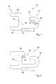
- Fig. 1 is shown in plan view the end face of a first embodiment of a connecting profile 10 according to the invention, with the formation of so-called combi-sheet piles sheet piles are connected to support elements.
- the connecting profile 10 has a constant cross-sectional shape and is adapted in its length to the length of the sheet piles and support elements to be joined together.
- the connection profile 10 has a central strip 12 on which a connection profile 14 and a receiving profile 16 are integrally formed. While the connection profile 14 is used for suspending a lock element of the sheet pile, the receiving profile 16 is used for attaching the connection profile 10 to the support element, as will be explained later.
- connection profile 14 has a near the one longitudinal edge of the central strip 12 from the central strip 12 approximately at right angles protruding transition portion 18, which merges into an at least approximately semicircular in the direction of the central strip 12 extending hook portion 20.
- the end of the hook portion 20 merges into an end portion 22 which is parallel to the transition portion 18.
- the ratio of the inner radius R j of the bent hook section 20 to the length L, of the transition section is approximately 1: 4.
- the ratio of the length L 2 of the end section 22 to the length L 1 of the transition section 18 corresponds approximately to the ratio 1: 3 in the illustrated embodiment, the transition portion 18, for example, a length L 1 of 38mm, while the inner radius R j of the hook portion 20 has a dimension of 7mm and the end portion 22 has a length L 2 of about 13mm.
- connection profile 14 extending in the longitudinal direction of the connection profile 10, one side open receiving channel 24 is formed, in which the lock element of the sheet pile is hooked for connection to the connection profile 10.
- the receiving profile 16 has two likewise approximately at right angles from the central strip 12 projecting retaining strips 26 and 28, which merge into the longitudinal edges of the central strip 12 flush.
- the two retaining strips 26 and 28 are parallel to each other and at least approximately the same length.
- the carrier element for example a double-T-carrier, with a cross-sectionally approximately rectangular or square holding portion between the retaining strips 26 and 28 is inserted.
- the connecting profile 10 is additionally secured by welding at least one of the retaining strips 26 and 28 on the holding portion of the support element
- connection profile 10 shown in this connection profile 40 is additionally integrally formed on the flat side of the central strip 42 to which the connection profile 44, which is also approximately perpendicular to the flat side of the central strip 42 and thus parallel to the transition section 48 of the connection profile 44 and flush in one of the two longitudinal edges of the central strip 42 passes.
- the support strip 46 is formed relative to the connection profile 44 on the central strip 42, that the support bar 46 projects into the opening portion 50 of the receiving channel 52 of the connection profile 44 and this partially covers, the insertion of the lock element in the receiving channel 52 but not hindered.
- the length L 3 of the support bar 46 is chosen so that the ratio between the length L 3 of the support bar 46 and the length L 1 of the transition section 48 is approximately 1: 4, in the illustrated embodiment, therefore, a length L 3 of about 10th mm has.
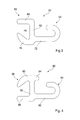
- FIG. 3 a second embodiment of a connecting profile 60 according to the invention is shown.
- the connecting profile 60 also has a central strip 62 on which a connection profile 64 and a receiving profile 66 are integrally formed.
- the connection profile 64 corresponds in its training in the Fig. 1 or 2 shown connection profile 14 and 44, so that a further description of the connection profile 64 can be omitted.
- the receiving profile 66 also has two retaining strips 68 and 70, wherein the first retaining strip 68, which is integrally formed on the longitudinal edge of the central strip 62 formed by the transition section 72, protrudes approximately at right angles from the flat side of the central strip 62.
- the second retaining strip 70 which immediately adjacent to the transition section 72 protrudes from the central strip 62, however, extends at an angle of approximately 45 ° inclined to the flat side of the central strip 62 to the first retaining strip 68 and ends at about the same height as the first retaining strip 68.
- This is a cross-section approximately triangular retaining channel 74th formed, which serves for receiving a cross-sectionally approximately wedge-shaped holding portion of a so-called lobe carrier, as will be explained later.
- Fig. 4 shows in plan view a connection profile 80, a development of in Fig. 3
- the connection profile 80 likewise has a central strip 82, on which a connection profile 84 and a receiving profile 86 are formed.
- the two retaining strips 88 and 90 of the receiving profile 86 are formed mirror-inverted compared to the connecting profile 60 on the central strip 82, so that the integrally formed near the transition portion 92 of the connection profile 84 retaining strip 88 is perpendicular to the longitudinal direction of the central strip 82, while the Retaining strip 90 is inclined at an angle of about 45 ° to the first retaining strip 88.
- connection profile 80 can be mirror-inverted to a lobe support so that the connection profile 84 can be fastened in the opposite direction to the lobe support compared to the connection profile 64 of the connection profile 60.
- a support bar 94 is provided, soft with the connection profile 84 in the reference to Fig. 2 cooperates manner described.
- a section of a combi-sheet piling 100 is shown, which is formed from a plurality of double-T-beams 102 and two each between two of the double-T-beams 102 arranged, cold-rolled sheet piles 104.
- the U-sheet piles 104 are interconnected by lock elements 106 and 108.
- connection profiles 10 and 40 are used, wherein the connection profile 10 with its connection profile 14 pointing inwards to the in Fig. 5 Right double T-beam 102 shown attached.
- the double-T-beams 102 are formed in a conventional manner and have two seen in cross-section approximately rectangular T-bar 110.
- FIG. 6 shows in which an enlarged section of the Fig. 5 is shown at the free end of the T-bar 110 of the in Fig. 5 left double T-beam 102 shown the invention Attached connection profile 40, which is attached with its receiving profile on the end of the T-bar 110.
- the two lock elements 106 and 108 of the U-sheet piles 104 are formed substantially identical and have as an essential connection element on a straight holding portion 112, which merges into a semicircular curved hook strip 114.
- the length of the holding portion 112 and the inner radius of the hook strip 114 are dimensioned such that the lock element 106 and 108 is securely held in the connection profile 44 of the connection profile 40 and can support itself properly in this, wherein the support bar 46 formed near the connection profile 44 slipping out of the lock element 108 from the receiving channel 52 prevents.
- connection profile 40 can be used in the same way, the connection profile 10.
- U-sheet piles or Z-sheet piles can be used which have been produced by hot rolling.
- FIG. 7 a section of a second embodiment of a combi-sheet pile wall 120 is shown.
- the combination sheet pile wall 120 has a plurality of lobe carriers 122 as carrier elements, wherein in each case two U sheet piles 124 are inserted between in each case two mutually adjacent lobe carriers 122.
- the U-sheet piles 124 correspond to the previously described U-sheet piles 104 and are also connected by correspondingly shaped lock members 126 and 128 with each other.
- each one lock element 126 of the sheet piles 124 is positioned with its hook strip facing inwards, while the other lock element 128 faces outward.
- connection profile 60 is used, which due to the design of the receiving profile 66 with its connection profile 64 inwardly pointing on the lobe support 122 can be attached, while in contrast the connection profile 80 with its connection profile 84 connection profile 84 pointing outwards on the other lobe support 122 is attached.
- FIG. 8 an enlarged view of a portion of the combi-sheet pile wall 120 is shown, in which with the one of the lobe support 122 and one of the U-sheet piles 124 engaged connection profile 60 is shown.
- the Verblndungsprofil 60 is fitted with its receiving profile 86 on a wedge-shaped widening in cross-section holding portion 130 which is formed at the end of one of the T-beams 132 of the lobe support 122, so that the connection profile 80 in a defined position on the lobe support 122 is held.
- the connection profile 64 engages with the lock element 126 of the U-shaped sheet pile 124 as previously described with reference to the combination sheet pile wall 100. In a corresponding manner, the sheet pile 124 is secured to the other lobe support 122 via the connection profile 60.
Landscapes
- Engineering & Computer Science (AREA)
- Structural Engineering (AREA)
- Chemical & Material Sciences (AREA)
- Composite Materials (AREA)
- Life Sciences & Earth Sciences (AREA)
- General Life Sciences & Earth Sciences (AREA)
- Mining & Mineral Resources (AREA)
- Paleontology (AREA)
- Civil Engineering (AREA)
- General Engineering & Computer Science (AREA)
- Bulkheads Adapted To Foundation Construction (AREA)
- Joining Of Building Structures In Genera (AREA)
Applications Claiming Priority (1)
| Application Number | Priority Date | Filing Date | Title |
|---|---|---|---|
| EP05002204A EP1688544A1 (fr) | 2005-02-02 | 2005-02-02 | Profilé de liaison des palplanches et cloison à structure mixte avec tel profilé |
Related Parent Applications (1)
| Application Number | Title | Priority Date | Filing Date |
|---|---|---|---|
| EP05002204.5 Division | 2005-02-02 |
Publications (1)
| Publication Number | Publication Date |
|---|---|
| EP2568083A1 true EP2568083A1 (fr) | 2013-03-13 |
Family
ID=34933567
Family Applications (2)
| Application Number | Title | Priority Date | Filing Date |
|---|---|---|---|
| EP12187444A Withdrawn EP2568083A1 (fr) | 2005-02-02 | 2005-02-02 | Profilé de liaison de palplanches et cloison mixte avec un tel profilé |
| EP05002204A Withdrawn EP1688544A1 (fr) | 2005-02-02 | 2005-02-02 | Profilé de liaison des palplanches et cloison à structure mixte avec tel profilé |
Family Applications After (1)
| Application Number | Title | Priority Date | Filing Date |
|---|---|---|---|
| EP05002204A Withdrawn EP1688544A1 (fr) | 2005-02-02 | 2005-02-02 | Profilé de liaison des palplanches et cloison à structure mixte avec tel profilé |
Country Status (8)
| Country | Link |
|---|---|
| US (1) | US7857550B2 (fr) |
| EP (2) | EP2568083A1 (fr) |
| CN (1) | CN101146959B (fr) |
| BR (1) | BRPI0606566A2 (fr) |
| CA (1) | CA2596823A1 (fr) |
| EA (1) | EA016298B1 (fr) |
| MX (1) | MX2007009314A (fr) |
| WO (1) | WO2006082041A1 (fr) |
Families Citing this family (17)
| Publication number | Priority date | Publication date | Assignee | Title |
|---|---|---|---|---|
| EP2034095A1 (fr) * | 2007-09-05 | 2009-03-11 | Kyoung Hae Park | Structure d'installation pour mur de rétention de terre |
| DE102008006353B4 (de) * | 2008-01-28 | 2010-01-14 | Pilepro Llc | Verbindungselement zum Anschließen von Spundbohlen an Trägerelemente sowie Kombi-Spundwand mit einem derartigen Verbindungselement |
| DE102008011795A1 (de) * | 2008-02-29 | 2009-09-03 | Contexo Ag | Verbindungselement sowie Spundwand mit derartigem Verbindungselement |
| DE102008013443A1 (de) | 2008-03-10 | 2009-09-17 | Contexo Ag | Verbindungselement sowie Spundwand mit einem derartigen Verbindungselement |
| US8801324B2 (en) * | 2010-08-17 | 2014-08-12 | Production Resource Group, L.L.C | Cable slider with symmetric pieces |
| US9506212B2 (en) | 2011-04-21 | 2016-11-29 | Pilepro Llc | Universal connecting element for sheet pile wall components |
| US10184219B2 (en) * | 2014-07-11 | 2019-01-22 | Saferoads Pty Ltd | Barrier connection system and connector for use therein |
| USD743775S1 (en) * | 2014-09-19 | 2015-11-24 | University Of Houston | Cage joining lock |
| USD807159S1 (en) * | 2016-03-23 | 2018-01-09 | Richard Heindl | Connecting element for sheet piles |
| DE202016101909U1 (de) * | 2016-04-11 | 2017-07-12 | Achim Wünsch | Spundwandelemente, Spundwände, und Zwischenstück für derartige Spundwände |
| US11021845B1 (en) * | 2019-12-02 | 2021-06-01 | Cmi Limited Co. | Sheet piling filler-corner |
| USD947015S1 (en) * | 2020-07-22 | 2022-03-29 | Richard Heindl | Sheet pile connector |
| USD1119550S1 (en) * | 2022-05-17 | 2026-03-24 | Pilepro Gmbh | Sheet pile building material |
| USD1013487S1 (en) * | 2022-12-07 | 2024-02-06 | Richard Heindl | Sheet pile connector |
| CA223296S (en) * | 2023-02-06 | 2024-09-24 | Heindl Richard | Sheet pile accessory |
| USD1054844S1 (en) | 2023-02-06 | 2024-12-24 | Richard Heindl | Sheet pile |
| JP1791352S (ja) * | 2023-03-16 | 2025-02-18 | シートパイル用連結具 |
Citations (9)
| Publication number | Priority date | Publication date | Assignee | Title |
|---|---|---|---|---|
| DE1038769B (de) | 1955-06-11 | 1958-09-11 | Philips Nv | Vorrichtung zum Messen der Geschwindigkeit von Fluessigkeitsstroemen |
| EP0072118A1 (fr) | 1981-07-31 | 1983-02-16 | Dawson Construction Plant Limited | Elément de construction destiné à l'usage des fondations sur pieux |
| DE29718052U1 (de) | 1997-03-18 | 1997-12-04 | Fried. Krupp Ag Hoesch-Krupp, 45143 Essen Und 44145 Dortmund | Verbundschloß und Spundwand |
| DE29810933U1 (de) * | 1998-06-18 | 1998-09-24 | Krings Dielen GmbH, 52525 Heinsberg | Spundwandprofil |
| DE19716685A1 (de) * | 1997-04-21 | 1998-10-29 | Georg Wall | Verbindungselement für Spundbohlen |
| US6042306A (en) * | 1997-03-18 | 2000-03-28 | Preussag Stahl | Connecting lock and sheet pile wall |
| US6443664B1 (en) * | 1998-07-31 | 2002-09-03 | Corus Uk Limited | Metal sheet piling |
| USD471794S1 (en) * | 2001-09-17 | 2003-03-18 | Georg Wall | Connection element for sheet piles |
| DE20121712U1 (de) * | 2001-12-07 | 2003-05-08 | Wall, Georg, 81375 München | Strangförmiges Trägerelement zum Aufbau von Wänden, insbesondere Spundwänden |
Family Cites Families (16)
| Publication number | Priority date | Publication date | Assignee | Title |
|---|---|---|---|---|
| US1431273A (en) * | 1922-04-04 | 1922-10-10 | Ransome Machinery Company 1920 | Metallic sheeting and locking bar |
| US1431274A (en) * | 1922-04-04 | 1922-10-10 | Ransome Machinery Company 1920 | Metallic sheeting and locking bar |
| US1837787A (en) * | 1926-04-30 | 1931-12-22 | Meiser Josef | Iron coffer-dam pile |
| US1918886A (en) * | 1926-05-31 | 1933-07-18 | Dougree Marihaye Sa | Sheet pile |
| US1690499A (en) * | 1927-08-22 | 1928-11-06 | Nolte Karl | Connecting piece for iron sheet piling |
| US1851864A (en) * | 1928-07-13 | 1932-03-29 | Nolte Karl | Joint for connecting sheet piling members |
| US2104490A (en) * | 1936-01-18 | 1938-01-04 | Kohler Willem Coenraad | Hollow pile for sheet pilings |
| LU88743A1 (fr) * | 1996-04-17 | 1997-10-17 | Profilarbed Sa | Procédé pour raccorder une palplanche à une poutrelle |
| DE19618204A1 (de) * | 1996-05-07 | 1997-11-13 | Kvh Verbautechnik Gmbh | Spundwandprofil |
| DE20017445U1 (de) * | 2000-10-11 | 2001-03-08 | Wall, Georg, 81375 München | Verbindungselement für Spundbohlen |
| DE20302716U1 (de) | 2003-02-19 | 2003-06-18 | Wall, Georg, 81375 München | Bauelementesatz zum Errichten einer Kombi-Spundwand |
| DE102004019953B3 (de) * | 2004-04-23 | 2005-12-08 | Pilepro Llc | Strangförmiges Verbindungsprofil zum Anschließen von Spundbohlen an Trägerelemente |
| DE102004024103B3 (de) * | 2004-05-14 | 2006-01-05 | Pilepro Llc | Strangförmiges Verbindungsprofil zum Anschließen von Spundbohlen an Trägerelemente |
| USD525862S1 (en) * | 2004-11-25 | 2006-08-01 | Pilepro, Llc | Connecting element for sheet piles |
| USD521364S1 (en) * | 2004-11-29 | 2006-05-23 | Pilepro, Llc | Connecting element for sheet piles |
| USD543841S1 (en) * | 2005-05-09 | 2007-06-05 | Pilepro, Llc | Connecting element for sheet piles |
-
2005
- 2005-02-02 EP EP12187444A patent/EP2568083A1/fr not_active Withdrawn
- 2005-02-02 EP EP05002204A patent/EP1688544A1/fr not_active Withdrawn
-
2006
- 2006-02-01 US US11/883,592 patent/US7857550B2/en active Active - Reinstated
- 2006-02-01 WO PCT/EP2006/000880 patent/WO2006082041A1/fr not_active Ceased
- 2006-02-01 MX MX2007009314A patent/MX2007009314A/es active IP Right Grant
- 2006-02-01 CN CN200680009743.9A patent/CN101146959B/zh not_active Expired - Fee Related
- 2006-02-01 CA CA002596823A patent/CA2596823A1/fr not_active Abandoned
- 2006-02-01 BR BRPI0606566-0A patent/BRPI0606566A2/pt not_active IP Right Cessation
- 2006-02-01 EA EA200701638A patent/EA016298B1/ru not_active IP Right Cessation
Patent Citations (9)
| Publication number | Priority date | Publication date | Assignee | Title |
|---|---|---|---|---|
| DE1038769B (de) | 1955-06-11 | 1958-09-11 | Philips Nv | Vorrichtung zum Messen der Geschwindigkeit von Fluessigkeitsstroemen |
| EP0072118A1 (fr) | 1981-07-31 | 1983-02-16 | Dawson Construction Plant Limited | Elément de construction destiné à l'usage des fondations sur pieux |
| DE29718052U1 (de) | 1997-03-18 | 1997-12-04 | Fried. Krupp Ag Hoesch-Krupp, 45143 Essen Und 44145 Dortmund | Verbundschloß und Spundwand |
| US6042306A (en) * | 1997-03-18 | 2000-03-28 | Preussag Stahl | Connecting lock and sheet pile wall |
| DE19716685A1 (de) * | 1997-04-21 | 1998-10-29 | Georg Wall | Verbindungselement für Spundbohlen |
| DE29810933U1 (de) * | 1998-06-18 | 1998-09-24 | Krings Dielen GmbH, 52525 Heinsberg | Spundwandprofil |
| US6443664B1 (en) * | 1998-07-31 | 2002-09-03 | Corus Uk Limited | Metal sheet piling |
| USD471794S1 (en) * | 2001-09-17 | 2003-03-18 | Georg Wall | Connection element for sheet piles |
| DE20121712U1 (de) * | 2001-12-07 | 2003-05-08 | Wall, Georg, 81375 München | Strangförmiges Trägerelement zum Aufbau von Wänden, insbesondere Spundwänden |
Non-Patent Citations (1)
| Title |
|---|
| FOSTER PILING: "Piling catalog: chapter Piling accessories: Pile connectors", 16 September 2004, FOSTER PILING, XP002335396 * |
Also Published As
| Publication number | Publication date |
|---|---|
| CN101146959B (zh) | 2012-05-30 |
| MX2007009314A (es) | 2008-02-21 |
| WO2006082041A1 (fr) | 2006-08-10 |
| US20080145154A1 (en) | 2008-06-19 |
| EA016298B1 (ru) | 2012-04-30 |
| EP1688544A1 (fr) | 2006-08-09 |
| CA2596823A1 (fr) | 2006-08-10 |
| CN101146959A (zh) | 2008-03-19 |
| EA200701638A1 (ru) | 2008-02-28 |
| US7857550B2 (en) | 2010-12-28 |
| BRPI0606566A2 (pt) | 2009-07-07 |
Similar Documents
| Publication | Publication Date | Title |
|---|---|---|
| EP1698733B1 (fr) | Paroi métallique constituée de palplanches | |
| DE102008006353B4 (de) | Verbindungselement zum Anschließen von Spundbohlen an Trägerelemente sowie Kombi-Spundwand mit einem derartigen Verbindungselement | |
| EP1907634B1 (fr) | Profile de liaison servant a fixer des palplanches sur des elements de support, et cloison de palplanches combinee equipee de ce profile de liaison | |
| WO2010133380A1 (fr) | Élément de liaison pour palplanches | |
| EP2568083A1 (fr) | Profilé de liaison de palplanches et cloison mixte avec un tel profilé | |
| EP3673115B1 (fr) | Profilé de raccordement pour palplanches de type larssen | |
| DE202016101909U1 (de) | Spundwandelemente, Spundwände, und Zwischenstück für derartige Spundwände | |
| EP1939359A1 (fr) | Profil de liaison destiné à fixer des palplanches ensembles | |
| DE102007020747A1 (de) | Anordnung aus mehreren Spundwandkomponenten sowie Anschweißprofil hierfür | |
| WO2005111315A1 (fr) | Profile de raccord pour raccorder des palplanches a des elements de support, et paroi de palplanches comprenant un profile de raccord de ce type | |
| DE102007027940A1 (de) | Verbindungselement und Spundwand mit einem derartigen Verbindungselement | |
| WO2005103392A1 (fr) | Profile d'assemblage extrude destine au raccordement de palplanches sur des elements supports | |
| DE10318769A1 (de) | Kombi-Spundwand | |
| WO2006058761A1 (fr) | Element de connexion de palplanches | |
| DE102007027939A1 (de) | Verbindungsprofil sowie Spundwand mit derartigem Verbindungsprofil | |
| EP1902186A1 (fr) | Dispositif d'assemblage | |
| CH644438A5 (de) | Hohlprofilstab, insbesondere fuer tor- oder zaunpfosten. | |
| EP1601842A1 (fr) | Elements d'armature et pieces en beton arme ou precontraint produites avec ces elements d'armature | |
| DE202006021134U1 (de) | Anordnung aus Spundwandkomponenten | |
| DE19851877A1 (de) | Verbindungselement für Spundbohlen | |
| DE202014102114U1 (de) | Abdeckung eines Untergrundes | |
| WO2000028157A1 (fr) | Element de liaison destine a des palplanches metalliques | |
| DE202005022056U1 (de) | Verbindungsprofil und Kombi-Spundwand mit einem derartigen Verbindungsprofil | |
| DE29821624U1 (de) | Verbindungselement für Spundbohlen | |
| DE202005022065U1 (de) | Kombi-Spundwand |
Legal Events
| Date | Code | Title | Description |
|---|---|---|---|
| PUAI | Public reference made under article 153(3) epc to a published international application that has entered the european phase |
Free format text: ORIGINAL CODE: 0009012 |
|
| AC | Divisional application: reference to earlier application |
Ref document number: 1688544 Country of ref document: EP Kind code of ref document: P |
|
| AK | Designated contracting states |
Kind code of ref document: A1 Designated state(s): AT BE BG CH CY CZ DE DK EE ES FI FR GB GR HU IE IS IT LI LT LU MC NL PL PT RO SE SI SK TR |
|
| RIN1 | Information on inventor provided before grant (corrected) |
Inventor name: WENDT, ROB R. Inventor name: HEINDL, RICHARD Inventor name: WALL, GEORG |
|
| 17P | Request for examination filed |
Effective date: 20130913 |
|
| RBV | Designated contracting states (corrected) |
Designated state(s): AT BE BG CH CY CZ DE DK EE ES FI FR GB GR HU IE IS IT LI LT LU MC NL PL PT RO SE SI SK TR |
|
| 17Q | First examination report despatched |
Effective date: 20161223 |
|
| STAA | Information on the status of an ep patent application or granted ep patent |
Free format text: STATUS: THE APPLICATION IS DEEMED TO BE WITHDRAWN |
|
| 18D | Application deemed to be withdrawn |
Effective date: 20170503 |