EP2568091B1 - Procédé pour monter un plafond suspendu et ledit plafond suspendu - Google Patents
Procédé pour monter un plafond suspendu et ledit plafond suspendu Download PDFInfo
- Publication number
- EP2568091B1 EP2568091B1 EP11180133.8A EP11180133A EP2568091B1 EP 2568091 B1 EP2568091 B1 EP 2568091B1 EP 11180133 A EP11180133 A EP 11180133A EP 2568091 B1 EP2568091 B1 EP 2568091B1
- Authority
- EP
- European Patent Office
- Prior art keywords
- ceiling
- tiles
- suspended ceiling
- suspended
- tile
- Prior art date
- Legal status (The legal status is an assumption and is not a legal conclusion. Google has not performed a legal analysis and makes no representation as to the accuracy of the status listed.)
- Not-in-force
Links
- 238000000034 method Methods 0.000 title claims description 22
- 239000000463 material Substances 0.000 claims description 35
- 239000000835 fiber Substances 0.000 claims description 13
- 239000011491 glass wool Substances 0.000 claims description 7
- 229910052500 inorganic mineral Inorganic materials 0.000 claims description 5
- 239000011707 mineral Substances 0.000 claims description 5
- 239000002699 waste material Substances 0.000 description 20
- 238000010521 absorption reaction Methods 0.000 description 18
- 239000011358 absorbing material Substances 0.000 description 12
- 239000002344 surface layer Substances 0.000 description 6
- 239000004033 plastic Substances 0.000 description 4
- 229920003023 plastic Polymers 0.000 description 4
- 238000007789 sealing Methods 0.000 description 4
- 239000000725 suspension Substances 0.000 description 4
- 210000002105 tongue Anatomy 0.000 description 4
- 239000000853 adhesive Substances 0.000 description 3
- 230000001070 adhesive effect Effects 0.000 description 3
- 230000000694 effects Effects 0.000 description 3
- 230000007613 environmental effect Effects 0.000 description 3
- 238000009966 trimming Methods 0.000 description 3
- 230000006870 function Effects 0.000 description 2
- 238000009434 installation Methods 0.000 description 2
- 238000009413 insulation Methods 0.000 description 2
- 239000010410 layer Substances 0.000 description 2
- 239000011490 mineral wool Substances 0.000 description 2
- 238000009423 ventilation Methods 0.000 description 2
- 208000032041 Hearing impaired Diseases 0.000 description 1
- 229910000831 Steel Inorganic materials 0.000 description 1
- 239000006096 absorbing agent Substances 0.000 description 1
- 239000004411 aluminium Substances 0.000 description 1
- 229910052782 aluminium Inorganic materials 0.000 description 1
- XAGFODPZIPBFFR-UHFFFAOYSA-N aluminium Chemical compound [Al] XAGFODPZIPBFFR-UHFFFAOYSA-N 0.000 description 1
- 239000011248 coating agent Substances 0.000 description 1
- 238000000576 coating method Methods 0.000 description 1
- 230000000295 complement effect Effects 0.000 description 1
- 238000010276 construction Methods 0.000 description 1
- 230000003247 decreasing effect Effects 0.000 description 1
- 230000001419 dependent effect Effects 0.000 description 1
- 238000005265 energy consumption Methods 0.000 description 1
- 230000002349 favourable effect Effects 0.000 description 1
- 230000009970 fire resistant effect Effects 0.000 description 1
- 230000001788 irregular Effects 0.000 description 1
- 229910052751 metal Inorganic materials 0.000 description 1
- 239000002184 metal Substances 0.000 description 1
- 238000012986 modification Methods 0.000 description 1
- 230000004048 modification Effects 0.000 description 1
- 239000004745 nonwoven fabric Substances 0.000 description 1
- 239000003973 paint Substances 0.000 description 1
- 229920000573 polyethylene Polymers 0.000 description 1
- 210000001747 pupil Anatomy 0.000 description 1
- 238000004064 recycling Methods 0.000 description 1
- 239000010959 steel Substances 0.000 description 1
- 238000004381 surface treatment Methods 0.000 description 1
- 230000000007 visual effect Effects 0.000 description 1
- 230000003313 weakening effect Effects 0.000 description 1
- 239000002759 woven fabric Substances 0.000 description 1
Images




Classifications
-
- E—FIXED CONSTRUCTIONS
- E04—BUILDING
- E04B—GENERAL BUILDING CONSTRUCTIONS; WALLS, e.g. PARTITIONS; ROOFS; FLOORS; CEILINGS; INSULATION OR OTHER PROTECTION OF BUILDINGS
- E04B9/00—Ceilings; Construction of ceilings, e.g. false ceilings; Ceiling construction with regard to insulation
- E04B9/22—Connection of slabs, panels, sheets or the like to the supporting construction
-
- E—FIXED CONSTRUCTIONS
- E04—BUILDING
- E04B—GENERAL BUILDING CONSTRUCTIONS; WALLS, e.g. PARTITIONS; ROOFS; FLOORS; CEILINGS; INSULATION OR OTHER PROTECTION OF BUILDINGS
- E04B1/00—Constructions in general; Structures which are not restricted either to walls, e.g. partitions, or floors or ceilings or roofs
- E04B1/62—Insulation or other protection; Elements or use of specified material therefor
- E04B1/74—Heat, sound or noise insulation, absorption, or reflection; Other building methods affording favourable thermal or acoustical conditions, e.g. accumulating of heat within walls
- E04B1/82—Heat, sound or noise insulation, absorption, or reflection; Other building methods affording favourable thermal or acoustical conditions, e.g. accumulating of heat within walls specifically with respect to sound only
-
- E—FIXED CONSTRUCTIONS
- E04—BUILDING
- E04B—GENERAL BUILDING CONSTRUCTIONS; WALLS, e.g. PARTITIONS; ROOFS; FLOORS; CEILINGS; INSULATION OR OTHER PROTECTION OF BUILDINGS
- E04B9/00—Ceilings; Construction of ceilings, e.g. false ceilings; Ceiling construction with regard to insulation
- E04B9/001—Ceilings; Construction of ceilings, e.g. false ceilings; Ceiling construction with regard to insulation characterised by provisions for heat or sound insulation
-
- E—FIXED CONSTRUCTIONS
- E04—BUILDING
- E04B—GENERAL BUILDING CONSTRUCTIONS; WALLS, e.g. PARTITIONS; ROOFS; FLOORS; CEILINGS; INSULATION OR OTHER PROTECTION OF BUILDINGS
- E04B1/00—Constructions in general; Structures which are not restricted either to walls, e.g. partitions, or floors or ceilings or roofs
- E04B1/62—Insulation or other protection; Elements or use of specified material therefor
- E04B1/74—Heat, sound or noise insulation, absorption, or reflection; Other building methods affording favourable thermal or acoustical conditions, e.g. accumulating of heat within walls
- E04B2001/742—Use of special materials; Materials having special structures or shape
- E04B2001/746—Recycled materials, e.g. made of used tires, bumpers or newspapers
Definitions
- the present invention relates to a method for mounting a suspended ceiling, comprising providing a supporting structure and ceiling tiles, and installing said ceiling tiles in the supporting structure.
- the present invention also relates to a suspended ceiling.
- Suspended ceilings can be installed in many different types of buildings for various reasons, for example to absorb sound, to reflect light, to lower the ceiling height or to conceal installations such as cable arrangements, ventilation equipment, lighting installations and other devices arranged in the space between the suspended ceiling and the ceiling structure of a building.
- a suspended ceiling usually comprises a plurality of ceiling tiles and a supporting structure such as a grid.
- the grid comprises profiles which support the ceiling tiles.
- the grid often comprises main runners which are suspended to the ceiling structure of the building and transverse or cross runners which are supported by the main runners.
- the profiles usually have an inverted T-shape or L-shape.
- the ceiling tiles may have sound-absorbing and/or sound-insulation properties in order to improve the acoustic environment of the room.
- the ceiling tiles for instance, may be made of a compressed fibre material such as mineral wool and especially glass wool.
- ceiling tiles normally being quadrangular a continuous grid pattern is formed. In order to provide an aesthetical appearance, symmetry should be strived for. However, since the ceiling tiles are provided in a limited number of sizes, this means that the ceiling tiles along the walls normally have to be cut to fit. In fact, cutting is in most cases necessary no matter if symmetry is a requirement or not.
- the easiest way to form symmetry is to make a drawing according to scale and mark a reference point.
- a reference point could be a centreline or a point of intersection depending on whether the area is a corridor or a room.
- the continuous grid pattern is adapted to the reference point whereby the perimeter becomes symmetrical, i.e. the width of the ceiling tiles along two opposing walls becomes the same.
- Ceiling tiles are provided in a number of dimensions, normally quadrangular.
- the quadrangular tiles are provided in a great variety of edge designs, such as geometrical profiles, surface treatments, brackets and trimmings depending on the intended mounting, joint type and visual appearance. Accordingly, two opposing edges may not be identical.
- the ceiling tiles are cut. This means a lot of superfluous material, and especially in the case when the two opposing edges are not identical, since the cut away tile portion cannot be used to form the perimeter by simply turning the tile. Turning is also often impossible due to orientation in the surface.
- about 3-8 % of the original area of the ceiling tiles becomes waste material after the ceiling tiles have been cut to fit the room.
- the smaller the size of the room the larger amount of waste material is formed, since a higher proportion of the ceiling tiles, compared to a larger room, have to be cut in order to fit the room.
- the amount of waste also varies due to the size of the tiles; bigger format means more cut away.
- the room layout is an important factor, irregular rooms mean more waste material.
- This waste material must be taken care of in some way, for example be recycled or transported to a landfill site. This implies that the waste material must be transported from the building wherein the suspended ceiling has been installed to a location where the waste material can be taken care of. This transportation of waste material results in environmental impacts and costs. Ceiling tiles are firstly transported to the building location, and waste material is once again transported away from the building location. Further, superfluous ceiling tiles has been produced, thereby creating costs and environmental influence, which material fills no function when reaching the building location, thus resulting in waste of material and resources.
- a suspended ceiling comprising a first set of tiles and a second set of tiles.
- the first set of tiles forms a perimeter arranged in a plane different from the plane of the second set of tiles.
- a suspended ceiling comprising ceiling tiles having a variable thickness.
- a further object is to improve the sound-absorbing properties of a suspended ceiling.
- a further object is to provide an improved way of taking care of superfluous material resulting from mounting of the suspended ceiling.
- a method for mounting a suspended ceiling in a room comprising providing a supporting structure and ceiling tiles, and installing said ceiling tiles in the supporting structure.
- the method is characterized in that a ceiling tile is adapted to the size and shape of the room by removing a superfluous tile portion, the adapted ceiling tile is installed in the suspended ceiling, said a superfluous portion is arranged on top of the already installed ceiling tiles of said suspended ceiling.
- the ceiling tile from which the superfluous portion is removed may have sound absorbing properties.
- the ceiling tile may be made of compressed fibre material, preferably mineral fibre, and most preferably glass wool.
- One or more superfluous portions removed from ceiling tiles may be arranged on top of the installed ceiling tiles of the suspended ceiling. Said one or more superfluous portions may be removed from a single ceiling tile, or may be removed from more than one ceiling tile.
- the ceiling tile from which the superfluous portion is removed is one of the ceiling tiles forming said suspended ceiling.
- the ceiling tiles When mounting a suspended ceiling, the ceiling tiles have to be adapted to fit the size of the room.
- a portion of the ceiling tile is removed, for example by cutting.
- one or more ceiling tiles have to be cut. Thereby, one or more portions are removed from one or more ceiling tiles. Normally, these portions are considered as waste material which has to be transported away from the building where the suspended ceiling is mounted in order to be for example recycled.
- the sound-absorbing capacity of the suspended ceiling is especially improved at low frequencies, for example about 125 Hz.
- Absorption at low frequencies is important for good speech listening conditions. Absorption at low frequencies is very important in educational premises, and especially for hearing-impaired children and pupils with other native language than the language of the country. Low frequency sounds can interfere in a negative way with speech and reduce the ability to understand the spoken words. This will impede learning and concentration.
- uniform sound absorption coefficient curve is meant that the sound absorption coefficient is essentially the same in the entire frequency range.
- the sound absorption coefficient may be increased by 0,5 by arranging portions removed from ceiling tiles above the suspended ceiling.
- the increase of the sound absorption coefficient depends on the number and size of portions arranged above the suspended ceiling and the size of the room.
- Another advantage is that portions removed from the ceiling tiles, i.e. superfluous material, do not have to be transported away from the location where the suspended ceiling is mounted in order to be destroyed or recycled.
- the unnecessary transport in order to return some of the material which previously has been transported to the building site is reduced. Thereby, the environmental impact and energy consumption due to transport of superfluous material resulting from the suspended ceiling is reduced. Further, costs are decreased.
- Using the removed portions as additional sound absorbing material provides a more efficient exploitation of the material.
- the superfluous material is only to be taken care of when the complete suspended ceiling is to be dismounted after its life span, and can be handled in the same way as and together with the rest of the suspended ceiling. Thereby, no additional transport is needed for the superfluous material.
- the person mounting the suspended ceiling does not have to collect portions removed from ceiling tiles and bring them to a specific container.
- the portions may be arranged above the suspended ceiling as he/she mounts the suspended ceiling. Thereby, the time for mounting the suspended ceiling is reduced.
- the portions removed from ceiling tiles is arranged on top of the suspended ceiling, but may also be attached to the ceiling structure or suspension means.
- the ceiling tile from which said superfluous portion is removed is included in the suspended ceiling.
- the portions which have to be removed for adjusting the ceiling tiles to the size and shape of the room are used as additional sound absorbing material arranged on top of the installed ceiling tiles of the suspended ceiling.
- the step of installing said ceiling tiles may comprise adapting at least one ceiling tile by removing said portion from said at least one ceiling tile.
- the ceiling tiles have to be adjusted to the shape and size of the room by removing a portion of the ceiling tile, for example by cutting.
- superfluous material is formed, which can be arranged above the suspended ceiling as additional sound absorbing material.
- Portions removed from other ceiling tiles adapted to form a suspended ceiling in one room can be used as additional sound absorbing material in another room.
- portions removed from ceiling tiles which are to be arranged in one room can be moved and arranged above a suspended ceiling in a room where the need for additional sound absorbing capacity is higher than in the first room.
- additional material can be moved to be arranged in a class room.
- portions can be moved to a room where the ceiling tiles fit the size and shape of the room without any adjusting or with only small adjustments.
- the method may further comprise arranging said superfluous portion on top of the installed ceiling tiles of said suspended ceiling adjacent a wall.
- the sound absorbing capacity of the suspended ceiling is especially increased if the superfluous portion is arranged adjacent a wall. Arranging sound absorbing material along the wall, i.e. in the perimeter, reduces reverberation.
- the ceiling tiles arranged adjacent the wall usually are cut, the ceiling tiles forming the perimeter conventionally are not dismountable. It is advantageous to arrange the superfluous portion above such ceiling tiles, since the risk that the portion falls down when the ceiling tile is dismounted is reduced.
- the method may further comprise arranging said superfluous portion on top of the installed ceiling tiles of said suspended ceiling in a corner.
- the sound absorbing capacity of the suspended ceiling is especially increased if the superfluous portion is arranged in a corner of the room. Arranging sound absorbing material in the corner reduces reverberation and cue-ball reflections.
- the ceiling tiles arranged in the corner usually are cut, the ceiling tiles in the corner conventionally are not dismountable. It is advantageous to arrange the portion above such ceiling tiles, since the risk that the superfluous portion falls down when the ceiling tile is dismounted is reduced.
- the method may further comprise arranging said superfluous portion in an enclosure on top of the already installed ceiling tiles. By collecting the superfluous portion in an enclosure, the handling of the portion is facilitated.
- a plurality of superfluous portions may be arranged in said enclosure.
- the enclosure may be arranged in the vicinity of the assembler, and the assembler may place the superfluous portions in the enclosure as he/she removes the portions from the ceiling tiles. Further, by placing the superfluous portions in enclosures, the portions are collected to certain spots above the suspended ceiling, which facilitates if a ceiling tile is to be dismounted.
- One or more superfluous portions may be arranged in a plurality of enclosures. Said plurality of enclosures may further be distributed above said suspended ceiling. By arranging the superfluous portions in a plurality of enclosures, the portions may be distributed over the area of the suspended ceiling.
- Said plurality of enclosures may be distributed such that sound absorbing properties of the suspended ceiling is optimised.
- the enclosures for example arranging enclosures in the corners and along the walls, the sound absorbing capacity of the suspended ceiling is further improved.
- the method may further comprise attaching said enclosure to the supporting structure. Thereby, the enclosure is prevented from falling down if a ceiling tile of the suspended ceiling is dismounted.
- the method may further comprise arranging an entire ceiling tile on top of the installed ceiling tiles of the suspended ceiling.
- an entire ceiling tile is meant a ceiling tile from which no portion has been removed, i.e. an uncut ceiling tile.
- the uncut ceiling tile may be a spare ceiling tile which is stored above the suspended ceiling until needed. When being stored above the suspended ceiling, the spare ceiling tile improves the sound absorbing properties of the suspended ceiling.
- the spare ceiling tile may be of the same type of the ceiling tiles forming the suspended ceiling.
- the spare ceiling tile may be made of compressed fibre material and comprise a surface layer.
- Said ceiling tile may be made of compressed fibre material, preferably mineral fibre, most preferably glass wool.
- a ceiling tile of compressed fibre material has sound absorbing properties.
- Fig. 1 shows a suspended ceiling 1 comprising profiles 10, 11 forming a supporting structure, and ceiling tiles 2 arranged in a room as seen from above.
- the profiles 10, 11 are adapted to support the ceiling tiles 2.
- the profiles 10, 11 may be main runners 10, cross runners 11 and/or wall runners (not shown).
- the main runners 10 are commonly suspended from the structural ceiling or building frame work or the like.
- the suspension may e.g. be provided using hangers 3 formed of wires or interconnected plate shaped members or the like.
- the main runners 10 are commonly arranged equidistantly and parallel to each other.
- the supporting structure further comprises a plurality of cross runners 11 extending between the main runners 10.
- the cross runners 11 are provided with connecting members at their respective ends and engage with the main runners 10. They may also be supported by the main runners 10.
- the cross runners 11 are commonly arranged equidistantly and parallel to each other, and commonly transverse to the main runners 10, thereby forming a grid. Cross runners 11 may also be arranged parallel to the main runners 10.
- the supporting structure thus formed provides a plurality of quadratic or rectangular openings into which the ceiling tiles 2 are adapted to be placed.
- the profiles 10, 11 may have an inverted T-shape.
- the profiles 10, 11 comprise a flange and a web.
- the flange is adapted to form a support surface for supporting the ceiling tiles 2.
- the web may be provided with a bulb.
- the ceiling tiles 2 have a front surface, a rear surface opposite the front surface and one or more edge surfaces extending between the front and rear surfaces.
- the front surface may be provided with a surface layer.
- the rear surface may also be provided with a surface layer.
- the edge surfaces may be provided with a surface layer.
- the front and/or the rear surface may be painted.
- the ceiling tiles 2 have sound-absorbing and/or sound-insulation properties in order to improve the acoustic environment of a room.
- the ceiling tile 2 may be made of man-made mineral fibre.
- the ceiling tiles 2 are made of a compressed fibre material such as mineral wool and most preferably glass wool.
- the supporting structure When mounting the suspended ceiling 1, the supporting structure is formed by arranging profiles, for instance by arranging main runners 10 and cross runners 11.
- the main runners 10 are suspended to the ceiling structure of the building by means of suspension means such as hangers 3.
- the ceiling tiles 2 are then arranged in the openings formed by the supporting structure.
- the ceiling tiles 2 are supported by the supporting structure.
- the suspended ceiling in fig. 1 covers 1 the entire area of the ceiling of the room. However, the size and shape of the room rarely corresponds to the exact size of one or more the ceiling tiles 2.
- a reference point P is constituted by the geometrical centre point of the ceiling.
- the reference point P may by way of example be positioned in a centre ceiling tile 2 or in a point of intersection between four ceiling tiles 2 in the middle of the suspended ceiling 1 as in fig. 1 . This means that in most cases, a portion 2b of all ceiling tiles 2a arranged adjacent the walls of the room have to be removed in order adjust the ceiling tiles 2 to the available area of the room.
- the row of ceiling tiles 2a closest to the walls is generally referred to as a perimeter or a frieze.
- the ceiling tiles 2 may be adjusted by cutting a portion 2b of the ceiling tile 2a.
- all perimeter ceiling tiles 2a have been cut in order to adjust the suspended ceiling 1 to the size and shape of the room. Consequently, when mounting the suspended ceiling 1, adapting the ceiling tiles 2a to the size and shape of the room comprises removing a portion 2b of the ceiling tile 2a, for example by cutting.
- Cutting the ceiling tile 2a means that the cut off portion 2b generally becomes waste material for a number of reasons. In most cases, the cut off portion 2b is simply too small to be re-used in the perimeter. Also, in most cases, the opposing edges of a ceiling tile 2 are not symmetrical, whereby it is not possible to turn the cut off tile portion 2b 180 degrees to fit an adjacent tile. Also, when cutting a ceiling tile 2, the cut edge must generally be restored, either in the form of a sealing or a trimming. Restoration is required not only for aesthetical reasons but also for a number of technical reasons, such as sealing the edge. Restoration in the form of a trimming may also be required to form a connecting means suitable to fit adjacent ceiling tiles or wall fittings.
- the portion 2b being removed from the ceiling tile 2a is arranged above the suspended ceiling 1, as disclosed in figs. 3 and 4 .
- the portion 2b being removed from the ceiling tile 2a may be arranged directly on top of the suspended ceiling 1 as shown in the figures, or attached to the ceiling structure of the building, or to the suspension means 3 suspending the suspended ceiling 1.
- on top of the suspended ceiling is meant that the portion is arranged on a surface of the suspended ceiling facing the ceiling structure of the building.
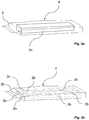
- the portion 2b being removed from a ceiling tile 2a is arranged in an enclosure 4, as shown in fig. 2a .
- the enclosure is in form of a pouch, sack or bag.
- the enclosure 4 may be made of plastics, such as polyethene, glass wool, a non-woven or woven fabric.
- the enclosure 4 may be provided with a fire resistant coating.
- the enclosure 4 is acoustically transparent. By acoustically transparent is meant that sound energy may be transported through the enclosure.
- the surface weight of the enclosure for example a plastic bag, can be approximately 50 to 300 g/m 2 . Increased thickness in this range will give a minor increase of the low frequency absorption.
- the enclosure 4 may in one embodiment be air permeable. The required wall thickness of the enclosure 4 is dependent on whether the enclosure is air permeable or not. Sound in the low frequency range may pass through an air tight enclosure. In order to allow sound in the high frequency range to pass through the enclosure 4, the enclosure should be air permeable.
- the size of the enclosure 4 may for example be 500 x 700 x 300 mm.
- the enclosure 4 may have a shape of a rectangular parallelepiped.
- the enclosure 4 may be provided with a closure means for sealing the enclosure after the portion have been arranged in the enclosure.
- the closure means may be zip closure or a strip provided with an adhesive.
- the strip provided with an adhesive may be arranged on an end portion 5 of the enclosure.
- the closure means may be in form of a clip.
- the clip, or an additional clip may also be adapted to attach the enclosure to the supporting structure, for example to a main or cross runner.
- the clip may be attached to an end portion 5 to the enclosure 4 and attached to the supporting structure, which is shown in figs. 5 and 6 .
- a plurality of portions 2b has been arranged in an enclosure 4 of the type described above.
- the portions 2b have been removed from one or more ceiling tiles 2a when the ceiling tiles 2a have been cut in order to adapt to the size and shape of the room.
- the portions 2b may be arranged on top of each other in the enclosure in more than one layer.
- a plurality of portions 2b may be arranged beside each other in the enclosure 4.
- the portion or portions 2b removed from one or more ceiling tiles may have any shaped, and the shape is not restricted to the shape shown in figs. 2a-b .
- the enclosure 4 including one or more portions 2b being removed from ceiling tiles 2a has been arranged above the suspended ceiling 1 , preferably on top of the suspended ceiling 1.
- the enclosure 4 is arranged along the perimeter ceiling tiles 2a along the wall or in a corner of the suspended ceiling.
- the enclosure 4 may be attached to the supporting structure.
- the enclosure 4 may be arranged on top of one of the ceiling tiles 2, 2a or on top of one of the profiles 10, 11.
- fig. 4 more than one enclosure 4 have been arranged above the suspended ceiling 1.
- the enclosures 4 are of the type described above in connection with fig. 2a .
- One or more portions 2b being removed from one or more ceiling tiles 2a is arranged in each enclosure 4.
- the enclosures 4 have been distributed over the area of the suspended ceiling 1.
- the enclosures 4 are distributed such that the sound absorbing properties of the suspended ceiling 1 is optimised.
- the enclosures 4 are arranged above the perimeter ceiling tiles 2a along the walls and/or in the corner of the room.
- the enclosures 4 may be distributed in another way in order to optimise the sound absorbing properties of the suspended ceiling 1, depending of the size, shape and other properties of the room.
- the enclosures 4 may be attached to profiles 10, 11 of the supporting structure by means of a clip or similar.
- the cut-off portions 2b By arranging the portions 2b removed from ceiling tiles 2a on top the suspended ceiling 1, the cut-off portions 2b, usually considered as waste material, is used as additional sound absorbing material. Material considered as waste material thus increases the sound absorbing capacity of the suspended ceiling 1. Furthermore, the superfluous material does not have to be transported away in order to be taken care of.
- the portion or portions 2b removed from a ceiling tile 2a may be arranged directly on top of the suspended ceiling 1 without being arranged in any enclosure 4.
- the portion or portions 2b may also be arranged above the suspended ceiling 1 and be suspended to the ceiling structure.
- the ceiling tile 2a from which the portion 2b is removed or cut-off is included in the suspended ceiling 1.
- additional sound absorbing material may be taken from another suspended ceiling in the building and be added to the suspended ceiling 1.
- the ceiling tile 2a from which the portion 2b is removed or cut-off is not included in the suspended ceiling 1.
- cut-off portions 2b can be moved from a room wherein the need extra sound absorbing is lower to a room in which the need for extra sound absorbing is higher, for instance from a corridor to a class room.
- some of the ceiling tiles 2a from which the portions 2b are removed or cut-off is not included in the suspended ceiling 1.
- the portion 2b being removed from a ceiling tile 2a is not necessarily associated with one of the ceiling tiles 2 of the suspended ceiling 1.
- porous ceiling tiles have been arranged on top of the suspended ceiling, covering 30 to 40 % of the ceiling area, in order to reach very good acoustic conditions at 125 Hz.
- a 100 mm ceiling tile added to a typical absorption class A ceiling tile will increase the absorption coefficient at 125 Hz from 0.30 - 0.40 to 0.85 - 0.90.
- the reverberation time in unoccupied room is typically in the region 0.60 to 1.0 s at 125 Hz.
- the reverberation time will normally decrease to 0.40 to 0.50 s.
- a reverberation time of 0.40 to 0.50 at 125 Hz corresponds to very good low frequency conditions.
- Typical amount of superfluous material is approximately 6 to 8 % of the total ceiling area. For example, if the total ceiling area is 700 m 2 , the amount of superfluous material will be 49 m 2 (7% waste is assumed).
- the superfluous material i.e. portions removed from ceiling tile, is arranged above the suspended ceiling. If the superfluous material is arranged above the suspended ceiling such that it covers an area of 23 m 2 , this area corresponds to almost 40 % of a typical ceiling area in a classroom, i.e. 60 m 2 . As described above, covering 30-40 % of the ceiling area with ceiling tiles is enough to secure very good acoustic conditions at low frequencies.
- the superfluous material i.e. the portions being removed from ceiling tiles associated with the suspended ceiling in the same room or a suspended ceiling in another room, may be distributed over the area of the suspended ceiling.
- the enclosures will cover an area of 23 m 2 . Since this area is almost 40 % of a typical ceiling area in a classroom, i.e. 60 m 2 , the amount will be enough to secure very good acoustic conditions at low frequencies.
- the enclosure 4 is not required for achieving the desired effect.
- the portion or portions 2b removed from a ceiling tile 2a may be arranged directly above of the suspended ceiling 1 without being arranged in any enclosure 4.
- the enclosure 4 is preferably acoustically transparent such that sound energy may be transported through the enclosure 4.
- the absorbing efficiency at 125 Hz is approximately proportional to the amount of added equivalent absorption area. This means that even smaller amount added with superfluous material than 40% of the total ceiling area will improve the low frequency absorption, although the effect decrease if the area of added absorption material decrease. All additional material having sound absorbing properties will positively affect the low frequency absorption of the suspended ceiling.
- the enclosures 4 may be attached to the suspended ceiling 1 in order to prevent enclosures 4 from falling down if a ceiling tile 2, 2a is removed from the suspended ceiling 1.
- Fig. 5 shows an enclosure 4 arranged on top of the suspended ceiling 1.
- the enclosure 4 comprises an end portion 5 which is arranged such that the end profile 5 extends over a profile 10 of the supporting structure.
- the profile 10 may be a main runner, cross runner or any other type of profile.
- a clip 6 is attached to the profile 10 such that the end portion 5 of the enclosure 4 is attached to the profile.
- the web of the profile is provided with a bulb 12.
- the clip 6 is adapted to grip the bulb 12 of the profile.
- the clip 6 is adapted to enclose a top portion of the bulb 12.
- the end portion 5 of the enclosure 4 is arranged between the clip 6 and the bulb 12 such that the end portion 5 is attached to the bulb 12.
- more than one clip 5 may be arranged at the end portion 5 of the enclosure 4.
- Fig. 6 shows an alternative solution wherein the enclosure 4 is attached to a ceiling tile 2.
- a fastening member 7 is inserted through the end portion 5 of the enclosure 4 into the ceiling tile 2 such that the enclosure 4 is attached to the ceiling tile 2.
- the fastening member 7 is an L-shaped member.
- Fig. 7 discloses a holder 20 for the enclosures 4 in which the portions 2b are to be placed.
- the holder 20 is adapted to be arranged on a scaffolding or ladder (not shown) on which the person assembling the suspended ceiling 1 is standing.
- the assembler is placing the portion 2b being removed from a ceiling tile 2a in an enclosure 4 (not shown in fig. 7 ) arranged on the holder 20.
- the holder 20 comprises a plate 21.
- the holder 20 further comprises attaching means 25 for attaching and hanging the holder 20 on the scaffolding, preferably on a tubular scaffolding (not shown).
- the holder 20 further comprises holding means 22 for holding a plurality of enclosures 4.
- the holder comprises a frame 23 extending outwards from the plate 21 perpendicular from the plate 21. In the embodiment shown in fig. 7 , the frame 23 has two tongues 24. The tongues 24 are upwardly protruding.
- the frame 23 forms a loop on which an enclosure 4 may be passed in order to form an opening of the enclosure 4. An edge portion of the enclosure 4 may be passed over the tongue.
- the holder 20 may be formed from a sheet, for example a metal sheet of aluminium, steel etc.
- the attaching means 22 and/or the holding means 20 may be formed of cut-out portions of the sheet being folded.
- the holder 20 is adapted to hold a plurality of enclosures 4, in which portions 2b removed from a ceiling tile 2a may be placed.
- the enclosures 4 may be in form of bags.
- the bags may be plastic bags.
- a stack of bags may be arranged on the holder 20.
- the stack of bags has two apertures in which the holding means 22 may be inserted in order to suspend the stack of bags.
- a top portion of the bag may be passed over the frame 23 and the tongues 24 of the holder 20 in order to keep the bag opened.
- the stack of bags may be provided with a weakening portion, for example in form of a tear line, such that an individual bag may be torn off from the stack of bags.
- the bag may further be provided with a closure means, for instance a zip seal (not shown) or a strip provided with an adhesive.
- a closure means for instance a zip seal (not shown) or a strip provided with an adhesive.
- the bag may be sealed with a clip (not shown). This clip or a separate clip may be used to attach the bag to the profiles 10, 11 of the supporting structure.
- the bag When one bag is filled, the bag is torn off the stack and placed above the suspended ceiling 1. The assembler then opens a new bag by passing the top portion over the frame 23 on the holder 20.
- the holder 30 is adapted to be arranged on a scaffolding or ladder (not shown) on which the person assembling the suspended ceiling 1 is standing.
- the assembler is placing the portion 2b being removed from ceiling tile 2a in an enclosure 4 arranged on the holder 30.
- the holder 30 in fig. 8 comprises an annular portion 31, a flange 32 and attaching means 33.
- the flange 32 is extending perpendicular from a lower portion of the annular portion 31.
- the attaching means 33 are extending from the flange 32 and attached to the flange 32.
- the attaching means 33 are adapted to fasten the holder 30 to a scaffolding or ladder (not shown).
- the holder 30 is adapted to hold at least one enclosure 4.
- a top portion of the enclosure 4 is adapted to be passed over the annular portion 31.
- the enclosure 4 is in form of a bag, preferably plastic bag.
- the bag may be in form of an endless bag.
- the endless bag is divided into individual portions by sealing the end of the bag by means of a clip 35.
- the assembler then places portions 2b removed from at least one ceiling tile 2a in the bag.
- the assembler separates the part of the bag which is filled, for example by cutting the bag portion.
- the bag portion may then be sealed by means of an additional clip.
- the bag is then placed above the ceiling 1.
- the clip 35 may be used to attach the clip to the profiles 10, 11 of the supporting structure.
- an entire ceiling tile 2 i.e. a ceiling tile from which no portion has been removed or cut, may also be arranged above the suspended ceiling 1, preferably on top of the suspended ceiling 1.
- the ceiling tile may be an uncut ceiling tile.
- the ceiling tile may be of the type described above.
- the spare ceiling tile 2 is easily accessible when needed.
- the ceiling tile 2 arranged above the suspended ceiling 1 is of the same type as the ceiling tiles 2 forming the suspended ceiling 1.
- the spare ceiling tile 2 arranged above the suspended ceiling 1 is of a type which is adapted to face the interior of a room.
- the spare ceiling tile 2 and the ceiling tiles 2 forming the suspended ceiling 1 is made of compressed fibre material, preferably mineral fibre, and most preferably glass wool.
- the spare ceiling tile 2 and the ceiling tiles 2 forming the suspended ceiling 1 may each comprise at least one surface layer.
- the spare ceiling tile 2 and the ceiling tiles 2 forming the suspended ceiling 1 may each comprise at least one layer of paint.
- the ceiling tile may be arranged in an enclosure of the type described above.
- the spare ceiling tile 2 functions as additional sound absorbing material when arranged above the suspended ceiling 1. Thereby, the sound absorbing capacity of the suspended ceiling 1 is increased.
- the spare ceiling tile 2 is removed from above the suspended ceiling 1 and arranged in the position of the damaged ceiling tile.
- the method may include arranging a ceiling tile from which no portion have been removed or cut above the suspended ceiling, preferably on top of the suspended ceiling, in the above described manner.
- a ceiling tile from which no portion has been removed or cut is arranged above the suspended and no portion removed from ceiling tiles are arranged above the suspended ceiling.
- ceiling tiles from a suspended ceiling which is to be removed or replaced may be arranged above the suspended ceiling.
- One or more ceiling tiles from the suspended ceiling which is to be removed or replaced are arranged above, preferably on top of, another suspended ceiling.
- said one or more ceiling tiles are arranged in at least one enclosure.
- the enclosure and the ceiling tile may be of the above described type.
- the suspended ceiling on which the old ceiling tiles are placed may be a new suspended ceiling or an existing suspended ceiling. Also ceiling tiles which have been damaged can be used as additional sound absorbing material and be arranged above the suspended ceiling.
- the ceiling tiles which are to be arranged above the suspended ceiling may previously have been arranged in the same room, or have been arranged in a suspended ceiling in another room or in another building.
- the ceiling tile from which the portion is removed may not necessarily be a ceiling tile arranged adjacent a wall.
Landscapes
- Engineering & Computer Science (AREA)
- Architecture (AREA)
- Physics & Mathematics (AREA)
- Electromagnetism (AREA)
- Civil Engineering (AREA)
- Structural Engineering (AREA)
- Acoustics & Sound (AREA)
- Building Environments (AREA)
- Residential Or Office Buildings (AREA)
- Working Measures On Existing Buildindgs (AREA)
Claims (10)
- Procédé pour monter un plafond suspendu (1) dans une salle, comprenant
la fourniture d'une structure de support (10, 11) et de dalles de plafond (2) et
l'installation desdites dalles de plafond (2) dans la structure de support (10, 11), caractérisé en ce
qu'une dalle de plafond (2) est adaptée à la taille et à la forme de la salle par le retrait d'une partie de dalle superflue (2b),
la dalle de plafond adaptée (2a) est installée dans le plafond suspendu (1),
ladite partie superflue (2b) est agencée au-dessus des dalles de plafond (2) déjà installées dudit plafond suspendu (1). - Procédé selon la revendication 1, comprenant en outre l'agencement de ladite partie superflue (2b) au-dessus des dalles de plafond installées (2) dudit plafond suspendu (1) de façon adjacente à une paroi.
- Procédé selon la revendication 1 ou 2, comprenant en outre l'agencement de ladite partie superflue (2b) au-dessus des dalles de plafond installées (2) dudit plafond suspendu (1) dans un coin.
- Procédé selon l'une quelconque des revendications 1 à 3, comprenant en outre l'agencement de ladite partie superflue (2b) dans une enceinte (4) au-dessus des dalles de plafond déjà installées (2).
- Procédé selon la revendication 4, dans lequel une pluralité de parties superflues (2b) est agencée dans ladite enceinte (4).
- Procédé selon la revendication 4 ou 5, dans lequel une ou plusieurs partie(s) superflue(s) (2b) est/sont agencée(e) dans une pluralité d'enceintes (4) et comprenant en outre la distribution de ladite pluralité d'enceintes (4) au-dessus des dalles de plafond installées (2) dudit plafond suspendu (1).
- Procédé selon la revendication 6, dans lequel ladite pluralité d'enceintes (4) est répartie de telle façon que les propriétés d'absorption acoustique du plafond suspendu (1) sont optimisées.
- Procédé selon l'une quelconque des revendications 4 - 7, comprenant en outre la fixation de ladite enceinte (4) à la structure de support (10, 11).
- Procédé selon l'une quelconque des revendications 1 - 8, comprenant en outre l'agencement d'une dalle de plafond entière au-dessus des dalles de plafond installées (2) du plafond suspendu (1).
- Procédé selon l'une quelconque des revendications 1 - 9, dans lequel lesdites dalles de plafond (2, 2a, 2b) sont fabriquées en matériau de fibres compressées, de fibres minérales de préférence, de fibres de verre de la manière préférée entre toutes.
Priority Applications (2)
| Application Number | Priority Date | Filing Date | Title |
|---|---|---|---|
| EP11180133.8A EP2568091B1 (fr) | 2011-09-06 | 2011-09-06 | Procédé pour monter un plafond suspendu et ledit plafond suspendu |
| PCT/EP2012/066445 WO2013034449A2 (fr) | 2011-09-06 | 2012-08-23 | Procédé permettant de fixer un plafond suspendu, et plafond suspendu |
Applications Claiming Priority (1)
| Application Number | Priority Date | Filing Date | Title |
|---|---|---|---|
| EP11180133.8A EP2568091B1 (fr) | 2011-09-06 | 2011-09-06 | Procédé pour monter un plafond suspendu et ledit plafond suspendu |
Publications (2)
| Publication Number | Publication Date |
|---|---|
| EP2568091A1 EP2568091A1 (fr) | 2013-03-13 |
| EP2568091B1 true EP2568091B1 (fr) | 2017-07-05 |
Family
ID=46727216
Family Applications (1)
| Application Number | Title | Priority Date | Filing Date |
|---|---|---|---|
| EP11180133.8A Not-in-force EP2568091B1 (fr) | 2011-09-06 | 2011-09-06 | Procédé pour monter un plafond suspendu et ledit plafond suspendu |
Country Status (2)
| Country | Link |
|---|---|
| EP (1) | EP2568091B1 (fr) |
| WO (1) | WO2013034449A2 (fr) |
Families Citing this family (5)
| Publication number | Priority date | Publication date | Assignee | Title |
|---|---|---|---|---|
| JP2017020167A (ja) * | 2015-07-07 | 2017-01-26 | 大成建設株式会社 | 吸音部材 |
| US10506994B2 (en) * | 2017-08-29 | 2019-12-17 | General Electric Company | Apparatus for a radiographic device |
| FI3578734T3 (fi) * | 2018-06-04 | 2023-03-29 | Saint Gobain Ecophon Ab | Menetelmä laattamateriaalin kierrättämiseksi |
| CN113047629B (zh) * | 2021-03-18 | 2022-04-26 | 中国十七冶集团有限公司 | 一种异型空间吊顶安装方法 |
| CN116498034B (zh) * | 2023-03-24 | 2023-10-17 | 江苏汇宝不锈钢有限公司 | 不锈钢装饰板的强吸音结构及安装方法 |
Family Cites Families (3)
| Publication number | Priority date | Publication date | Assignee | Title |
|---|---|---|---|---|
| US2017548A (en) * | 1930-01-14 | 1935-10-15 | Maurice C Rosenblatt | Building construction |
| GB9604729D0 (en) * | 1996-03-06 | 1996-05-08 | Edinburgh Acoustical Co Ltd | Sound deadening panels |
| EP2090707B1 (fr) * | 2008-02-13 | 2013-05-29 | Saint-Gobain Ecophon AB | Plafond et son procédé d'agencement |
-
2011
- 2011-09-06 EP EP11180133.8A patent/EP2568091B1/fr not_active Not-in-force
-
2012
- 2012-08-23 WO PCT/EP2012/066445 patent/WO2013034449A2/fr not_active Ceased
Non-Patent Citations (1)
| Title |
|---|
| None * |
Also Published As
| Publication number | Publication date |
|---|---|
| EP2568091A1 (fr) | 2013-03-13 |
| WO2013034449A2 (fr) | 2013-03-14 |
| WO2013034449A3 (fr) | 2013-05-10 |
Similar Documents
| Publication | Publication Date | Title |
|---|---|---|
| EP2568091B1 (fr) | Procédé pour monter un plafond suspendu et ledit plafond suspendu | |
| US20200123772A1 (en) | Ceiling module | |
| US7120269B2 (en) | Lay-in tile speaker system | |
| US20100064618A1 (en) | Ceiling tile and edge suspension system | |
| US20120317915A1 (en) | Self-Hanging Notched Ceiling Tile | |
| US20070193131A1 (en) | Acoustical panel ceiling system | |
| WO2014004360A1 (fr) | Panneau en gypse pour plafond monolithique acoustique | |
| US8689505B2 (en) | Profile-bending means for frame to be pocketed | |
| KR20190006020A (ko) | 해양 윈도우 조립체 | |
| US20070102238A1 (en) | Acoustical panel using wood veneer | |
| WO1998026136A1 (fr) | Panneau de construction | |
| WO1998026136A9 (fr) | Panneau de construction | |
| US7643647B2 (en) | Lay-in tile speaker system | |
| US12286787B2 (en) | Gasketed ceiling system | |
| JP7015649B2 (ja) | 天井材の取付け方法 | |
| US9071899B2 (en) | Narrow ceiling panel speaker systems | |
| EP2090707B1 (fr) | Plafond et son procédé d'agencement | |
| WO2017139204A1 (fr) | Système de rail pour mur suspendu | |
| JP7772627B2 (ja) | 制気口ボックス及び天井ボードへの制気口ボックスの取付方法 | |
| KR20080038146A (ko) | 천장 타일 수선 방법 | |
| JP5799612B2 (ja) | 減圧養生工法 | |
| JP2021067084A (ja) | 天井材、および天井材の製造方法 | |
| US11280088B2 (en) | Monolithic ceiling system | |
| JP2024032615A (ja) | 換気装置の取り付け方法及び換気装置の交換方法 | |
| EP2221426B1 (fr) | Plafond suspendu et procédé pour supporter un plafond suspendu |
Legal Events
| Date | Code | Title | Description |
|---|---|---|---|
| PUAI | Public reference made under article 153(3) epc to a published international application that has entered the european phase |
Free format text: ORIGINAL CODE: 0009012 |
|
| AK | Designated contracting states |
Kind code of ref document: A1 Designated state(s): AL AT BE BG CH CY CZ DE DK EE ES FI FR GB GR HR HU IE IS IT LI LT LU LV MC MK MT NL NO PL PT RO RS SE SI SK SM TR |
|
| AX | Request for extension of the european patent |
Extension state: BA ME |
|
| 17P | Request for examination filed |
Effective date: 20130829 |
|
| RBV | Designated contracting states (corrected) |
Designated state(s): AL AT BE BG CH CY CZ DE DK EE ES FI FR GB GR HR HU IE IS IT LI LT LU LV MC MK MT NL NO PL PT RO RS SE SI SK SM TR |
|
| STAA | Information on the status of an ep patent application or granted ep patent |
Free format text: STATUS: EXAMINATION IS IN PROGRESS |
|
| 17Q | First examination report despatched |
Effective date: 20161202 |
|
| GRAP | Despatch of communication of intention to grant a patent |
Free format text: ORIGINAL CODE: EPIDOSNIGR1 |
|
| STAA | Information on the status of an ep patent application or granted ep patent |
Free format text: STATUS: GRANT OF PATENT IS INTENDED |
|
| INTG | Intention to grant announced |
Effective date: 20170217 |
|
| GRAS | Grant fee paid |
Free format text: ORIGINAL CODE: EPIDOSNIGR3 |
|
| GRAA | (expected) grant |
Free format text: ORIGINAL CODE: 0009210 |
|
| STAA | Information on the status of an ep patent application or granted ep patent |
Free format text: STATUS: THE PATENT HAS BEEN GRANTED |
|
| AK | Designated contracting states |
Kind code of ref document: B1 Designated state(s): AL AT BE BG CH CY CZ DE DK EE ES FI FR GB GR HR HU IE IS IT LI LT LU LV MC MK MT NL NO PL PT RO RS SE SI SK SM TR |
|
| REG | Reference to a national code |
Ref country code: GB Ref legal event code: FG4D |
|
| REG | Reference to a national code |
Ref country code: CH Ref legal event code: EP |
|
| REG | Reference to a national code |
Ref country code: AT Ref legal event code: REF Ref document number: 906710 Country of ref document: AT Kind code of ref document: T Effective date: 20170715 |
|
| REG | Reference to a national code |
Ref country code: IE Ref legal event code: FG4D |
|
| REG | Reference to a national code |
Ref country code: DE Ref legal event code: R096 Ref document number: 602011039268 Country of ref document: DE |
|
| REG | Reference to a national code |
Ref country code: FR Ref legal event code: PLFP Year of fee payment: 7 |
|
| REG | Reference to a national code |
Ref country code: NL Ref legal event code: MP Effective date: 20170705 |
|
| REG | Reference to a national code |
Ref country code: AT Ref legal event code: MK05 Ref document number: 906710 Country of ref document: AT Kind code of ref document: T Effective date: 20170705 |
|
| REG | Reference to a national code |
Ref country code: LT Ref legal event code: MG4D |
|
| PG25 | Lapsed in a contracting state [announced via postgrant information from national office to epo] |
Ref country code: NO Free format text: LAPSE BECAUSE OF FAILURE TO SUBMIT A TRANSLATION OF THE DESCRIPTION OR TO PAY THE FEE WITHIN THE PRESCRIBED TIME-LIMIT Effective date: 20171005 Ref country code: SE Free format text: LAPSE BECAUSE OF FAILURE TO SUBMIT A TRANSLATION OF THE DESCRIPTION OR TO PAY THE FEE WITHIN THE PRESCRIBED TIME-LIMIT Effective date: 20170705 Ref country code: AT Free format text: LAPSE BECAUSE OF FAILURE TO SUBMIT A TRANSLATION OF THE DESCRIPTION OR TO PAY THE FEE WITHIN THE PRESCRIBED TIME-LIMIT Effective date: 20170705 Ref country code: NL Free format text: LAPSE BECAUSE OF FAILURE TO SUBMIT A TRANSLATION OF THE DESCRIPTION OR TO PAY THE FEE WITHIN THE PRESCRIBED TIME-LIMIT Effective date: 20170705 Ref country code: HR Free format text: LAPSE BECAUSE OF FAILURE TO SUBMIT A TRANSLATION OF THE DESCRIPTION OR TO PAY THE FEE WITHIN THE PRESCRIBED TIME-LIMIT Effective date: 20170705 Ref country code: FI Free format text: LAPSE BECAUSE OF FAILURE TO SUBMIT A TRANSLATION OF THE DESCRIPTION OR TO PAY THE FEE WITHIN THE PRESCRIBED TIME-LIMIT Effective date: 20170705 Ref country code: LT Free format text: LAPSE BECAUSE OF FAILURE TO SUBMIT A TRANSLATION OF THE DESCRIPTION OR TO PAY THE FEE WITHIN THE PRESCRIBED TIME-LIMIT Effective date: 20170705 |
|
| PG25 | Lapsed in a contracting state [announced via postgrant information from national office to epo] |
Ref country code: PL Free format text: LAPSE BECAUSE OF FAILURE TO SUBMIT A TRANSLATION OF THE DESCRIPTION OR TO PAY THE FEE WITHIN THE PRESCRIBED TIME-LIMIT Effective date: 20170705 Ref country code: LV Free format text: LAPSE BECAUSE OF FAILURE TO SUBMIT A TRANSLATION OF THE DESCRIPTION OR TO PAY THE FEE WITHIN THE PRESCRIBED TIME-LIMIT Effective date: 20170705 Ref country code: GR Free format text: LAPSE BECAUSE OF FAILURE TO SUBMIT A TRANSLATION OF THE DESCRIPTION OR TO PAY THE FEE WITHIN THE PRESCRIBED TIME-LIMIT Effective date: 20171006 Ref country code: BG Free format text: LAPSE BECAUSE OF FAILURE TO SUBMIT A TRANSLATION OF THE DESCRIPTION OR TO PAY THE FEE WITHIN THE PRESCRIBED TIME-LIMIT Effective date: 20171005 Ref country code: IS Free format text: LAPSE BECAUSE OF FAILURE TO SUBMIT A TRANSLATION OF THE DESCRIPTION OR TO PAY THE FEE WITHIN THE PRESCRIBED TIME-LIMIT Effective date: 20171105 Ref country code: RS Free format text: LAPSE BECAUSE OF FAILURE TO SUBMIT A TRANSLATION OF THE DESCRIPTION OR TO PAY THE FEE WITHIN THE PRESCRIBED TIME-LIMIT Effective date: 20170705 Ref country code: ES Free format text: LAPSE BECAUSE OF FAILURE TO SUBMIT A TRANSLATION OF THE DESCRIPTION OR TO PAY THE FEE WITHIN THE PRESCRIBED TIME-LIMIT Effective date: 20170705 |
|
| REG | Reference to a national code |
Ref country code: DE Ref legal event code: R097 Ref document number: 602011039268 Country of ref document: DE |
|
| PG25 | Lapsed in a contracting state [announced via postgrant information from national office to epo] |
Ref country code: RO Free format text: LAPSE BECAUSE OF FAILURE TO SUBMIT A TRANSLATION OF THE DESCRIPTION OR TO PAY THE FEE WITHIN THE PRESCRIBED TIME-LIMIT Effective date: 20170705 Ref country code: DK Free format text: LAPSE BECAUSE OF FAILURE TO SUBMIT A TRANSLATION OF THE DESCRIPTION OR TO PAY THE FEE WITHIN THE PRESCRIBED TIME-LIMIT Effective date: 20170705 Ref country code: CZ Free format text: LAPSE BECAUSE OF FAILURE TO SUBMIT A TRANSLATION OF THE DESCRIPTION OR TO PAY THE FEE WITHIN THE PRESCRIBED TIME-LIMIT Effective date: 20170705 |
|
| REG | Reference to a national code |
Ref country code: CH Ref legal event code: PL |
|
| PLBE | No opposition filed within time limit |
Free format text: ORIGINAL CODE: 0009261 |
|
| STAA | Information on the status of an ep patent application or granted ep patent |
Free format text: STATUS: NO OPPOSITION FILED WITHIN TIME LIMIT |
|
| PG25 | Lapsed in a contracting state [announced via postgrant information from national office to epo] |
Ref country code: SM Free format text: LAPSE BECAUSE OF FAILURE TO SUBMIT A TRANSLATION OF THE DESCRIPTION OR TO PAY THE FEE WITHIN THE PRESCRIBED TIME-LIMIT Effective date: 20170705 Ref country code: IT Free format text: LAPSE BECAUSE OF FAILURE TO SUBMIT A TRANSLATION OF THE DESCRIPTION OR TO PAY THE FEE WITHIN THE PRESCRIBED TIME-LIMIT Effective date: 20170705 Ref country code: SK Free format text: LAPSE BECAUSE OF FAILURE TO SUBMIT A TRANSLATION OF THE DESCRIPTION OR TO PAY THE FEE WITHIN THE PRESCRIBED TIME-LIMIT Effective date: 20170705 Ref country code: MC Free format text: LAPSE BECAUSE OF FAILURE TO SUBMIT A TRANSLATION OF THE DESCRIPTION OR TO PAY THE FEE WITHIN THE PRESCRIBED TIME-LIMIT Effective date: 20170705 Ref country code: EE Free format text: LAPSE BECAUSE OF FAILURE TO SUBMIT A TRANSLATION OF THE DESCRIPTION OR TO PAY THE FEE WITHIN THE PRESCRIBED TIME-LIMIT Effective date: 20170705 |
|
| 26N | No opposition filed |
Effective date: 20180406 |
|
| REG | Reference to a national code |
Ref country code: IE Ref legal event code: MM4A |
|
| REG | Reference to a national code |
Ref country code: BE Ref legal event code: MM Effective date: 20170930 |
|
| PG25 | Lapsed in a contracting state [announced via postgrant information from national office to epo] |
Ref country code: LU Free format text: LAPSE BECAUSE OF NON-PAYMENT OF DUE FEES Effective date: 20170906 |
|
| PG25 | Lapsed in a contracting state [announced via postgrant information from national office to epo] |
Ref country code: IE Free format text: LAPSE BECAUSE OF NON-PAYMENT OF DUE FEES Effective date: 20170906 Ref country code: CH Free format text: LAPSE BECAUSE OF NON-PAYMENT OF DUE FEES Effective date: 20170930 Ref country code: LI Free format text: LAPSE BECAUSE OF NON-PAYMENT OF DUE FEES Effective date: 20170930 |
|
| REG | Reference to a national code |
Ref country code: FR Ref legal event code: PLFP Year of fee payment: 8 |
|
| PG25 | Lapsed in a contracting state [announced via postgrant information from national office to epo] |
Ref country code: BE Free format text: LAPSE BECAUSE OF NON-PAYMENT OF DUE FEES Effective date: 20170930 Ref country code: SI Free format text: LAPSE BECAUSE OF FAILURE TO SUBMIT A TRANSLATION OF THE DESCRIPTION OR TO PAY THE FEE WITHIN THE PRESCRIBED TIME-LIMIT Effective date: 20170705 |
|
| PG25 | Lapsed in a contracting state [announced via postgrant information from national office to epo] |
Ref country code: MT Free format text: LAPSE BECAUSE OF NON-PAYMENT OF DUE FEES Effective date: 20170906 |
|
| PG25 | Lapsed in a contracting state [announced via postgrant information from national office to epo] |
Ref country code: HU Free format text: LAPSE BECAUSE OF FAILURE TO SUBMIT A TRANSLATION OF THE DESCRIPTION OR TO PAY THE FEE WITHIN THE PRESCRIBED TIME-LIMIT; INVALID AB INITIO Effective date: 20110906 |
|
| PG25 | Lapsed in a contracting state [announced via postgrant information from national office to epo] |
Ref country code: CY Free format text: LAPSE BECAUSE OF NON-PAYMENT OF DUE FEES Effective date: 20170705 |
|
| PG25 | Lapsed in a contracting state [announced via postgrant information from national office to epo] |
Ref country code: MK Free format text: LAPSE BECAUSE OF FAILURE TO SUBMIT A TRANSLATION OF THE DESCRIPTION OR TO PAY THE FEE WITHIN THE PRESCRIBED TIME-LIMIT Effective date: 20170705 |
|
| PG25 | Lapsed in a contracting state [announced via postgrant information from national office to epo] |
Ref country code: TR Free format text: LAPSE BECAUSE OF FAILURE TO SUBMIT A TRANSLATION OF THE DESCRIPTION OR TO PAY THE FEE WITHIN THE PRESCRIBED TIME-LIMIT Effective date: 20170705 |
|
| PG25 | Lapsed in a contracting state [announced via postgrant information from national office to epo] |
Ref country code: PT Free format text: LAPSE BECAUSE OF FAILURE TO SUBMIT A TRANSLATION OF THE DESCRIPTION OR TO PAY THE FEE WITHIN THE PRESCRIBED TIME-LIMIT Effective date: 20170705 |
|
| PG25 | Lapsed in a contracting state [announced via postgrant information from national office to epo] |
Ref country code: AL Free format text: LAPSE BECAUSE OF FAILURE TO SUBMIT A TRANSLATION OF THE DESCRIPTION OR TO PAY THE FEE WITHIN THE PRESCRIBED TIME-LIMIT Effective date: 20170705 |
|
| PGFP | Annual fee paid to national office [announced via postgrant information from national office to epo] |
Ref country code: GB Payment date: 20220816 Year of fee payment: 12 Ref country code: DE Payment date: 20220817 Year of fee payment: 12 |
|
| PGFP | Annual fee paid to national office [announced via postgrant information from national office to epo] |
Ref country code: FR Payment date: 20220816 Year of fee payment: 12 |
|
| REG | Reference to a national code |
Ref country code: DE Ref legal event code: R119 Ref document number: 602011039268 Country of ref document: DE |
|
| GBPC | Gb: european patent ceased through non-payment of renewal fee |
Effective date: 20230906 |
|
| PG25 | Lapsed in a contracting state [announced via postgrant information from national office to epo] |
Ref country code: GB Free format text: LAPSE BECAUSE OF NON-PAYMENT OF DUE FEES Effective date: 20230906 |
|
| PG25 | Lapsed in a contracting state [announced via postgrant information from national office to epo] |
Ref country code: GB Free format text: LAPSE BECAUSE OF NON-PAYMENT OF DUE FEES Effective date: 20230906 Ref country code: FR Free format text: LAPSE BECAUSE OF NON-PAYMENT OF DUE FEES Effective date: 20230930 Ref country code: DE Free format text: LAPSE BECAUSE OF NON-PAYMENT OF DUE FEES Effective date: 20240403 |