EP2568120A2 - Turbinenmotorstator und Montageverfahren dafür - Google Patents
Turbinenmotorstator und Montageverfahren dafür Download PDFInfo
- Publication number
- EP2568120A2 EP2568120A2 EP12181345A EP12181345A EP2568120A2 EP 2568120 A2 EP2568120 A2 EP 2568120A2 EP 12181345 A EP12181345 A EP 12181345A EP 12181345 A EP12181345 A EP 12181345A EP 2568120 A2 EP2568120 A2 EP 2568120A2
- Authority
- EP
- European Patent Office
- Prior art keywords
- vanes
- cambered
- vane
- nominally
- group
- Prior art date
- Legal status (The legal status is an assumption and is not a legal conclusion. Google has not performed a legal analysis and makes no representation as to the accuracy of the status listed.)
- Granted
Links
Images


Classifications
-
- F—MECHANICAL ENGINEERING; LIGHTING; HEATING; WEAPONS; BLASTING
- F01—MACHINES OR ENGINES IN GENERAL; ENGINE PLANTS IN GENERAL; STEAM ENGINES
- F01D—NON-POSITIVE DISPLACEMENT MACHINES OR ENGINES, e.g. STEAM TURBINES
- F01D9/00—Stators
- F01D9/02—Nozzles; Nozzle boxes; Stator blades; Guide conduits, e.g. individual nozzles
- F01D9/04—Nozzles; Nozzle boxes; Stator blades; Guide conduits, e.g. individual nozzles forming ring or sector
- F01D9/041—Nozzles; Nozzle boxes; Stator blades; Guide conduits, e.g. individual nozzles forming ring or sector using blades
-
- F—MECHANICAL ENGINEERING; LIGHTING; HEATING; WEAPONS; BLASTING
- F01—MACHINES OR ENGINES IN GENERAL; ENGINE PLANTS IN GENERAL; STEAM ENGINES
- F01D—NON-POSITIVE DISPLACEMENT MACHINES OR ENGINES, e.g. STEAM TURBINES
- F01D9/00—Stators
- F01D9/02—Nozzles; Nozzle boxes; Stator blades; Guide conduits, e.g. individual nozzles
- F01D9/04—Nozzles; Nozzle boxes; Stator blades; Guide conduits, e.g. individual nozzles forming ring or sector
- F01D9/042—Nozzles; Nozzle boxes; Stator blades; Guide conduits, e.g. individual nozzles forming ring or sector fixing blades to stators
-
- F—MECHANICAL ENGINEERING; LIGHTING; HEATING; WEAPONS; BLASTING
- F01—MACHINES OR ENGINES IN GENERAL; ENGINE PLANTS IN GENERAL; STEAM ENGINES
- F01D—NON-POSITIVE DISPLACEMENT MACHINES OR ENGINES, e.g. STEAM TURBINES
- F01D9/00—Stators
-
- F—MECHANICAL ENGINEERING; LIGHTING; HEATING; WEAPONS; BLASTING
- F01—MACHINES OR ENGINES IN GENERAL; ENGINE PLANTS IN GENERAL; STEAM ENGINES
- F01D—NON-POSITIVE DISPLACEMENT MACHINES OR ENGINES, e.g. STEAM TURBINES
- F01D9/00—Stators
- F01D9/02—Nozzles; Nozzle boxes; Stator blades; Guide conduits, e.g. individual nozzles
- F01D9/04—Nozzles; Nozzle boxes; Stator blades; Guide conduits, e.g. individual nozzles forming ring or sector
- F01D9/042—Nozzles; Nozzle boxes; Stator blades; Guide conduits, e.g. individual nozzles forming ring or sector fixing blades to stators
- F01D9/044—Nozzles; Nozzle boxes; Stator blades; Guide conduits, e.g. individual nozzles forming ring or sector fixing blades to stators permanently, e.g. by welding, brazing, casting or the like
-
- F—MECHANICAL ENGINEERING; LIGHTING; HEATING; WEAPONS; BLASTING
- F04—POSITIVE - DISPLACEMENT MACHINES FOR LIQUIDS; PUMPS FOR LIQUIDS OR ELASTIC FLUIDS
- F04D—NON-POSITIVE-DISPLACEMENT PUMPS
- F04D29/00—Details, component parts, or accessories
- F04D29/40—Casings; Connections of working fluid
- F04D29/52—Casings; Connections of working fluid for axial pumps
- F04D29/54—Fluid-guiding means, e.g. diffusers
- F04D29/541—Specially adapted for elastic fluid pumps
- F04D29/542—Bladed diffusers
- F04D29/544—Blade shapes
-
- F—MECHANICAL ENGINEERING; LIGHTING; HEATING; WEAPONS; BLASTING
- F05—INDEXING SCHEMES RELATING TO ENGINES OR PUMPS IN VARIOUS SUBCLASSES OF CLASSES F01-F04
- F05D—INDEXING SCHEME FOR ASPECTS RELATING TO NON-POSITIVE-DISPLACEMENT MACHINES OR ENGINES, GAS-TURBINES OR JET-PROPULSION PLANTS
- F05D2240/00—Components
- F05D2240/10—Stators
- F05D2240/12—Fluid guiding means, e.g. vanes
-
- F—MECHANICAL ENGINEERING; LIGHTING; HEATING; WEAPONS; BLASTING
- F05—INDEXING SCHEMES RELATING TO ENGINES OR PUMPS IN VARIOUS SUBCLASSES OF CLASSES F01-F04
- F05D—INDEXING SCHEME FOR ASPECTS RELATING TO NON-POSITIVE-DISPLACEMENT MACHINES OR ENGINES, GAS-TURBINES OR JET-PROPULSION PLANTS
- F05D2240/00—Components
- F05D2240/80—Platforms for stationary or moving blades
-
- F—MECHANICAL ENGINEERING; LIGHTING; HEATING; WEAPONS; BLASTING
- F05—INDEXING SCHEMES RELATING TO ENGINES OR PUMPS IN VARIOUS SUBCLASSES OF CLASSES F01-F04
- F05D—INDEXING SCHEME FOR ASPECTS RELATING TO NON-POSITIVE-DISPLACEMENT MACHINES OR ENGINES, GAS-TURBINES OR JET-PROPULSION PLANTS
- F05D2250/00—Geometry
- F05D2250/30—Arrangement of components
- F05D2250/38—Arrangement of components angled, e.g. sweep angle
-
- F—MECHANICAL ENGINEERING; LIGHTING; HEATING; WEAPONS; BLASTING
- F05—INDEXING SCHEMES RELATING TO ENGINES OR PUMPS IN VARIOUS SUBCLASSES OF CLASSES F01-F04
- F05D—INDEXING SCHEME FOR ASPECTS RELATING TO NON-POSITIVE-DISPLACEMENT MACHINES OR ENGINES, GAS-TURBINES OR JET-PROPULSION PLANTS
- F05D2270/00—Control
- F05D2270/30—Control parameters, e.g. input parameters
- F05D2270/301—Pressure
-
- Y—GENERAL TAGGING OF NEW TECHNOLOGICAL DEVELOPMENTS; GENERAL TAGGING OF CROSS-SECTIONAL TECHNOLOGIES SPANNING OVER SEVERAL SECTIONS OF THE IPC; TECHNICAL SUBJECTS COVERED BY FORMER USPC CROSS-REFERENCE ART COLLECTIONS [XRACs] AND DIGESTS
- Y10—TECHNICAL SUBJECTS COVERED BY FORMER USPC
- Y10T—TECHNICAL SUBJECTS COVERED BY FORMER US CLASSIFICATION
- Y10T29/00—Metal working
- Y10T29/49—Method of mechanical manufacture
- Y10T29/49316—Impeller making
- Y10T29/4932—Turbomachine making
- Y10T29/49323—Assembling fluid flow directing devices, e.g., stators, diaphragms, nozzles
Definitions
- This invention relates to a stator for a turbomachine and particularly, but not exclusively, to a stator for a gas turbine engine, together with a method for assembling such a stator.
- a conventional axial flow gas turbine engine 10 comprises an air intake 11, a low pressure compressor (or fan) 12, an intermediate pressure compressor 13, a high pressure compressor 14, a combustor 15, a high pressure turbine 16, an intermediate pressure turbine 17, a low pressure turbine 18, and an exhaust nozzle 19.
- air is drawn into the engine 10 through the intake 11 and accelerated by the fan 12, to produce two air flows: a first air flow which enters the intermediate pressure compressor 13 and a second air flow which bypasses the core of the engine to provide direct propulsive thrust.
- the first air flow entering the intermediate pressure compressor 13 is compressed before entering the high pressure compressor 14 where further compression takes place.
- the compressed air leaving the high pressure compressor 14 is directed into the combustor 15 where it is mixed with fuel and the resulting mixture is combusted.
- the high pressure combustion products then rapidly expand as they pass through and drive the high, intermediate and low pressure turbines 16, 17 and 18.
- the gas leaving the low pressure turbine 18 is then exhausted through the exhaust nozzle 19 and provides additional propulsive thrust.
- the high, intermediate and low pressure turbines 16, 17 and 18 respectively drive the high and intermediate pressure compressors 14 and 13 and the fan 12 by means of separate interconnecting shafts.
- Typical axial-flow compressors and turbines each generally comprise a plurality of stages, each of which in turn comprises a stator stage which is mounted on the casing inner wall and a rotor stage which is rotatably driven in the casing.
- Each stator stage will typically comprise a plurality of individual stator vanes arranged as an annular array supported between respective inner and outer supports (or “platforms"), with each individual stator vane extending substantially radially between the platforms.
- the stator vanes in each stator stage are configured to straighten the air flow before it enters the adjacent rotor stage.
- a turbine engine stator stage comprising a plurality of vanes, each of the plurality of vanes having a camber angle, the method comprising the steps of:
- cyclic camber Such variation in the camber of the individual stator vanes around the circumference of the assembled stator stage is termed "cyclic camber”.
- method step (a) comprises the steps of:
- the stator includes a plurality of groups of stator vanes which include five different camber angles; these being defined as a nominal camber angle, 'nominal + 4°' and 'nominal + 8°' camber angles (termed “overcamber”) and 'nominal - 4°' and 'nominal - 8°' camber angles (termed “undercamber”).
- stator stage In order to simplify the manufacture of the stator stage it is therefore desirable to use a minimum quantity of discretely cambered vanes in an assembled stator stage.
- method step (b) comprises the steps of:
- vanes By arranging the vanes in groups in which a nominally cambered vane is positioned between one or more overcambered vanes and one or more undercambered vanes, it is possible to assemble the groups of vanes separately.
- the assembled groups of vanes may themselves then be positioned within the intermediate pressure compressor casing to form the assembled stator stage.
- This assembly technique makes the stator stage easier and quicker to assemble.
- each of the nominally cambered vane and an endmost of each of the undercambered and overcambered vanes in a group of vanes has a respective inspection feature, each inspection feature having a length, the method comprising the additional steps of:
- each of the nominally cambered vane and an endmost of each of the undercambered and overcambered vanes in a group of vanes With a respective inspection feature, it becomes possible to identify each of these types of vane simply by measuring some aspect (for example, a length) of the inspection feature.
- the inspection feature takes the form of a tang which protrudes from the outer platform of the vane.
- This check can be carried out using a simple GO / NO GO type inspection gauge which makes it easy for a user to quickly determine the quantity and order of vanes in the assembled stator stage.
- each group of vanes comprises the correct quantity of vanes, that the ordering of the vanes within the group is correct and, most importantly, that the group of vanes is correctly positioned circumferentially in the stator stage.
- the turbine engine stator stage further comprises a plurality of nominally cambered spacing vanes and wherein step (d) comprises the step of:
- each of the pre-assembled groups of vanes is separated by one or more spacing vanes. This enables specific groups of vanes to be positioned at the required circumferential position within the stator stage in order to achieve the required modification to the airflow through the stator stage.
- step (d1) comprises the additional initial step of:
- spacing vanes which have a range of nominal widths enables the separate groups of vanes to be positioned at the appropriate circumferential position in the stator stage whilst also enabling the expansion gap of the assembled stator stage to be controlled to the required limits.
- a turbine engine stator stage comprising a plurality of vanes, each of the plurality of vanes having a camber angle, the plurality of vanes being arranged in a plurality of groups, each group comprising a pre-determined sequence of vanes, the ordering of vanes within the sequence being determined by the camber of the individual vanes, and the circumferential position of each group within the stator stage being predetermined.
- each group comprises one nominally cambered vane, at least one over-cambered vane and at least one under-cambered vane.
- each of the plurality of vanes comprises an inner platform and an outer platform, each of the inner and outer platforms having a first side and an opposite second side, the first side of the inner platform of the nominally cambered vane and the second side of the inner platform of each of the at least one over-cambered vanes in each group each having respective co-operating angled first and second sides which enables each of the at least one over-cambered vanes to be consecutively positioned abutting the first side of the nominally cambered vane, and the second side of the outer platform of the nominally cambered vane and the first side of the outer platform of each of the at least one under-cambered vanes in each group each having respective co-operating angled second and first sides which enables each of the at least one under-cambered vanes to be consecutively positioned abutting the second side of the nominally cambered vane.
- the presence of angled sides on the interfacing sides of the inner platforms of the nominally cambered vane and the over-cambered vanes means that the over-cambered vanes can only be positioned on a first side of the nominally cambered vane if the resulting assembly of vanes is to form a planar group of vanes which can then form part of the assembled stator stage.
- the feature of co-operating pairs of sides on inner and outer platforms of the vanes means that the over-cambered and under-cambered vanes must be positioned on opposite sides of the nominally cambered vane. This makes it simpler for a user to assemble a group of vanes.
- the nominally cambered vane and the endmost of each of the undercambered and overcambered vanes in a group of vanes each comprise a respective inspection feature having a length, the length of the respective inspection feature identifying the nominally cambered vane and the undercambered and overcambered vanes at respective opposite ends of the sequence of vanes in the group.
- the plurality of groups of vanes comprises at least two groups of vanes, each group having a different sequence of over-cambered, nominally cambered and under-cambered vanes to each other group.
- each group of vanes is separated from an adjacent group by at least one nominally cambered spacing vane.
- stator stage further comprises an expansion gap and the spacing vane has a width such that the expansion gap of the assembled stator stage is within a predetermined limit.
- a turbine engine stator stage comprising a plurality of groups of vanes, each group of vanes comprising a nominally cambered vane, at least one over-cambered vane and at least one under-cambered vane, each of the vanes comprising an inner platform and an outer platform, each of the inner and outer platforms having a first side and an opposite second side, wherein within each group; the first side of the inner platform of the nominally cambered vane and the second side of the inner platform of each of the over-cambered vanes each having respective co-operating angled first and second sides which enables each of the over-cambered vanes to be consecutively positioned abutting the first side of the nominally cambered vane, and the second side of the outer platform of the nominally cambered vane and the first side of the outer platform of each of the under-cambered vanes each having respective co-operating angled second and first sides which enables each of the under-cambered va
- a turbine engine comprising a stator stage, the stator stage comprising a plurality of vanes, each of the plurality of vanes having a camber angle, the plurality of vanes being arranged in a plurality of groups, each group comprising a pre-determined sequence of vanes, the ordering of vanes within the sequence being determined by the camber of the individual vanes, and the circumferential position of each group within the stator stage being predetermined.
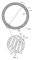
- a turbine engine stator stage according to the invention is designated generally by the reference numeral 100.
- the stator stage 100 comprises a plurality of stator vanes 120 which are arranged circumferentially in groups 170 to form the assembled stator stage 100 which is located inside the engine casing (not shown).
- the engine casing is split axially into two halves into each of which is assembled half of the stator stage 100.
- the two half engine casings are then joined at a later stage of the engine assembly to form the complete stator stage 100.
- the complete stator stage 100 is provided with an expansion gap 162 which allows for thermal expansion of the stator stage as the engine reaches its operating temperature.
- Each of the vanes 120 comprises an outer platform 130 which is integrally formed with an aerofoil portion 150 and an inner platform 140.
- the aerofoil portion 150 is cambered relative to the axis of the stator stage 100.
- the method of assembling the stator stage involves sliding individual vanes 120 into each of the engine casing halves in a predetermined sequence.
- the respective outer platforms 130 and inner platforms 140 of adjacent vanes 120 abut closely against one another in a circumferential manner.
- strut assemblies 154 which extend radially inwards from the engine casing, in order to support the shaft assembly. These strut assemblies 154 necessarily intrude into the air flow as it passes through the engine and may result in a loss of aerodynamic efficiency for the engine.
- the stator stage 100 comprises vanes 120 having a range of discrete camber values.
- Each vane 120 is configured as a vane 122 having a nominal camber angle, a vane 124,126 having a camber angle greater than the nominal angle (over-cambered) or a vane 128,129 having a camber less than the nominal angle (under-cambered).
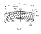
- Figures 3 and 4 show one such group 170 of vanes 120 having a single central nominally cambered vane 122 with five over-cambered vanes 124,126 positioned on one side of the central vane 122 and five under-cambered vanes 128,129 positioned on the other side of the central vane 122.
- the single nominally cambered vane 122 is aligned with the axis 156 of the strut 154.
- the over-cambered and under -cambered vanes 124,126,128,129 serve to direct the airflow around the strut 154. This has the effect of reducing the pressure loss caused by the presence of the strut 154 in the airflow, which in turn improves the efficiency of the engine.
- vanes 120 within the group shown in Figures 3 and 4 is symmetrical around the central vane 122, in other embodiments of the invention this arrangement may be asymmetrical.
- each vane has a first side 132 and an opposite second side 134
- the inner platform 140 of each vane 120 has corresponding first 142 and second 144 sides.
- the nominally cambered vane 122 is positioned between over-cambered vanes 124,126 and under-cambered vanes 128,129.
- the first sides 132,142 of the outer and inner platforms 130,140 of the central nominally cambered vane 122 are configured to abut against the corresponding second sides 134,144 of the over-cambered vanes 124,126.
- the second sides 134,144 of the outer and inner platforms 130,140 of the nominally cambered vane 122 are arranged to abut against the corresponding first sides 132,142 of the under-cambered vanes 128,129.
- first and second sides of each of the co-operating outer and inner platforms 130,140 are configured with a combination of sides either parallel to or angled relative to the axis of the stator stage 100.
- each outermost vane in each group 170 of vanes 120 is parallel to the stator stage 100 axis. This ensures that groups 170 of vanes can be assembled as part of the stator stage 100 in various different circumferential arrangements.
- each of the over-cambered 124,126 and under-cambered vanes 128,129 must be available in both end 124,128 (i.e. the end vane in a group) and mid 126,129 (i.e. between the nominally cambered vane 170 and an end vane) configurations.
- the first side 132 of the outer platform 130 of the nominally cambered vane 122 ( Figure 5 ) is parallel to the axis 166 of the stator stage 100 while the first side 142 of the inner platform 140 is angled at an angle ⁇ 1 to the stator assembly axis 166.
- the second side 134 of the outer platform 130 of both the end and mid over-cambered vanes 124,126 is parallel to the stator assembly axis 166 and the second side 144 of the inner platform 140 of these vanes 124,126 is angled at an angle ⁇ 1 to the stator assembly axis 166. This enables either of the end or mid over-cambered vanes 124,126 to abut against the first side 132,142 of the nominally cambered vane 122.
- the group 170 of vanes is to comprise more than one over-cambered vane 124,126, such as, say, five over-cambered vanes 124,126, as shown in Figures 3 and 4 , the group 170 will include one end 124 and four mid 126 over-cambered vanes.
- the second side 134 of the outer 130 platform of the nominally cambered vane 122 ( Figure 5 ) is angled at an angle ⁇ 2 to the stator assembly axis 166 while the second side 144 of the corresponding inner platform 140 is parallel to the axis of the stator stage 100.
- the first side 132 of the outer platform 130 of both the end and mid under-cambered vanes 128,129 is angled at an angle ⁇ 2 to the stator assembly axis 166 and the first side 142 of the inner platform 140 of each of these vanes 128,129 is parallel to the stator assembly axis 166.
- angles ⁇ 1 and ⁇ 2 are identical to one another. However in other embodiments these angles may be different to one another.
- the pre-assembled groups 170 of vanes 120 are then positioned in the compressor casing in a pre-determined sequence to form the completed stator stage 100.
- each of the nominally cambered vanes 122 is checked to ensure that it corresponds to the axis 156 of a strut 154.
- one or more spacing vanes 123 are positioned between the groups 170.
- the spacing vanes 123 are nominally cambered vanes which are available in a number of different widths, i.e. the distance between the first and second sides of the platforms.
Landscapes
- Engineering & Computer Science (AREA)
- Mechanical Engineering (AREA)
- General Engineering & Computer Science (AREA)
- Physics & Mathematics (AREA)
- Geometry (AREA)
- Turbine Rotor Nozzle Sealing (AREA)
- Structures Of Non-Positive Displacement Pumps (AREA)
Applications Claiming Priority (1)
| Application Number | Priority Date | Filing Date | Title |
|---|---|---|---|
| GB201115581A GB201115581D0 (en) | 2011-09-09 | 2011-09-09 | A turbine engine stator and method of assembly of the same |
Publications (3)
| Publication Number | Publication Date |
|---|---|
| EP2568120A2 true EP2568120A2 (de) | 2013-03-13 |
| EP2568120A3 EP2568120A3 (de) | 2017-12-27 |
| EP2568120B1 EP2568120B1 (de) | 2018-12-26 |
Family
ID=44908297
Family Applications (1)
| Application Number | Title | Priority Date | Filing Date |
|---|---|---|---|
| EP12181345.5A Active EP2568120B1 (de) | 2011-09-09 | 2012-08-22 | Turbinenmotorstator und Montageverfahren dafür |
Country Status (3)
| Country | Link |
|---|---|
| US (1) | US9062552B2 (de) |
| EP (1) | EP2568120B1 (de) |
| GB (1) | GB201115581D0 (de) |
Cited By (3)
| Publication number | Priority date | Publication date | Assignee | Title |
|---|---|---|---|---|
| WO2014143290A1 (en) * | 2013-03-15 | 2014-09-18 | United Technologies Corporation | Off-cambered vanes for gas turbine engines |
| US9593586B2 (en) | 2013-04-05 | 2017-03-14 | Rolls-Royce Plc | Vane assembly and method of making the same |
| EP3477060A1 (de) * | 2017-10-26 | 2019-05-01 | Rolls-Royce plc | Gehäuseanordnung und verfahren zur herstellung einer gehäuseanordnung für einen gasturbinenmotor |
Families Citing this family (5)
| Publication number | Priority date | Publication date | Assignee | Title |
|---|---|---|---|---|
| US9540938B2 (en) * | 2012-09-28 | 2017-01-10 | United Technologies Corporation | Pylon matched fan exit guide vane for noise reduction in a geared turbofan engine |
| JP6428128B2 (ja) * | 2014-10-08 | 2018-11-28 | 株式会社Ihi | 静翼構造、及びターボファンエンジン |
| DE102016212767A1 (de) | 2016-07-13 | 2018-01-18 | MTU Aero Engines AG | Verstellbares Turbomaschinen-Schaufelgitter |
| CN113623076B (zh) * | 2021-09-06 | 2022-07-22 | 中国联合重型燃气轮机技术有限公司 | 一种重型燃机进气缸 |
| CN119288912B (zh) * | 2024-11-07 | 2025-12-02 | 中国航发沈阳黎明航空发动机有限责任公司 | 一种压气机内部流场均匀性调整方法 |
Family Cites Families (13)
| Publication number | Priority date | Publication date | Assignee | Title |
|---|---|---|---|---|
| GB712589A (en) * | 1950-03-03 | 1954-07-28 | Rolls Royce | Improvements in or relating to guide vane assemblies in annular fluid ducts |
| FR2205927A5 (de) | 1972-11-08 | 1974-05-31 | Bertin & Cie | |
| US4131387A (en) * | 1976-02-27 | 1978-12-26 | General Electric Company | Curved blade turbomachinery noise reduction |
| GB2046849A (en) | 1979-04-17 | 1980-11-19 | Rolls Royse Ltd | Turbomachine strut |
| DE59709447D1 (de) * | 1997-11-17 | 2003-04-10 | Alstom Switzerland Ltd | Endstufe für axialdurchströmte Turbine |
| US7234914B2 (en) * | 2002-11-12 | 2007-06-26 | Continum Dynamics, Inc. | Apparatus and method for enhancing lift produced by an airfoil |
| GB2401654B (en) | 2003-05-14 | 2006-04-19 | Rolls Royce Plc | A stator vane assembly for a turbomachine |
| GB0314123D0 (en) * | 2003-06-18 | 2003-07-23 | Rolls Royce Plc | A gas turbine engine |
| GB2435309B (en) * | 2004-05-12 | 2007-10-10 | Rolls Royce Plc | A combination of an aircraft and a gas turbine engine |
| US8348600B2 (en) * | 2008-05-27 | 2013-01-08 | United Technologies Corporation | Gas turbine engine having controllable inlet guide vanes |
| US20090317237A1 (en) * | 2008-06-20 | 2009-12-24 | General Electric Company | System and method for reduction of unsteady pressures in turbomachinery |
| DE102008049358A1 (de) | 2008-09-29 | 2010-04-01 | Mtu Aero Engines Gmbh | Axiale Strömungsmaschine mit asymmetrischem Verdichtereintrittsleitgitter |
| US20110110763A1 (en) * | 2009-11-06 | 2011-05-12 | Dresser-Rand Company | Exhaust Ring and Method to Reduce Turbine Acoustic Signature |
-
2011
- 2011-09-09 GB GB201115581A patent/GB201115581D0/en not_active Ceased
-
2012
- 2012-08-22 EP EP12181345.5A patent/EP2568120B1/de active Active
- 2012-08-22 US US13/591,836 patent/US9062552B2/en active Active
Non-Patent Citations (1)
| Title |
|---|
| None |
Cited By (3)
| Publication number | Priority date | Publication date | Assignee | Title |
|---|---|---|---|---|
| WO2014143290A1 (en) * | 2013-03-15 | 2014-09-18 | United Technologies Corporation | Off-cambered vanes for gas turbine engines |
| US9593586B2 (en) | 2013-04-05 | 2017-03-14 | Rolls-Royce Plc | Vane assembly and method of making the same |
| EP3477060A1 (de) * | 2017-10-26 | 2019-05-01 | Rolls-Royce plc | Gehäuseanordnung und verfahren zur herstellung einer gehäuseanordnung für einen gasturbinenmotor |
Also Published As
| Publication number | Publication date |
|---|---|
| GB201115581D0 (en) | 2011-10-26 |
| US9062552B2 (en) | 2015-06-23 |
| EP2568120A3 (de) | 2017-12-27 |
| EP2568120B1 (de) | 2018-12-26 |
| US20130280054A1 (en) | 2013-10-24 |
Similar Documents
| Publication | Publication Date | Title |
|---|---|---|
| US9062552B2 (en) | Turbine engine stator and method of assembly of the same | |
| US10794396B2 (en) | Inlet pre-swirl gas turbine engine | |
| US10024193B2 (en) | Pin supported CMC shroud | |
| EP3026221B1 (de) | Leitschaufelanordnung, gasturbinenmotor und zugehöriges verfahren zur minderung von laufschaufelschwingungen | |
| US20180328187A1 (en) | Turbine engine with an airfoil and insert | |
| US10760589B2 (en) | Turbofan engine assembly and methods of assembling the same | |
| CN101776011B (zh) | 涡轮翼型件同步 | |
| EP3075967A1 (de) | Verfahren zur schaufelmontage und turbinenrahmen | |
| US8429816B2 (en) | Stator ring configuration | |
| US20170306768A1 (en) | Turbine engine shroud assembly | |
| US20160017732A1 (en) | Off-Cambered Vanes for Gas Turbine Engines | |
| CN106050314A (zh) | 涡轮框架和用于涡轮框架的翼型件 | |
| CN101666327A (zh) | 涡轮机翼型件的同步 | |
| US20070012046A1 (en) | Gas turbine intermediate structure and a gas turbine engine comprising the intermediate structure | |
| US10683809B2 (en) | Impeller-mounted vortex spoiler | |
| KR102712942B1 (ko) | 터빈 블레이드의 중심을 변위시키는 방법 및 시스템 | |
| EP3382147A1 (de) | Asymmetrische schaufelbaugruppe | |
| EP3584406A1 (de) | Klammer- und stiftausgleich für einen rotor | |
| US11060406B2 (en) | Rotor for gas turbine engine | |
| US20160305251A1 (en) | Gas turbine engine rotor mistuning | |
| CN101666269B (zh) | 涡轮机翼型件的同步 | |
| US11215084B2 (en) | Support straps and method of assembly for gas turbine engine | |
| US11401835B2 (en) | Turbine center frame | |
| US11415012B1 (en) | Tandem stator with depressions in gaspath wall |
Legal Events
| Date | Code | Title | Description |
|---|---|---|---|
| PUAI | Public reference made under article 153(3) epc to a published international application that has entered the european phase |
Free format text: ORIGINAL CODE: 0009012 |
|
| AK | Designated contracting states |
Kind code of ref document: A2 Designated state(s): AL AT BE BG CH CY CZ DE DK EE ES FI FR GB GR HR HU IE IS IT LI LT LU LV MC MK MT NL NO PL PT RO RS SE SI SK SM TR |
|
| AX | Request for extension of the european patent |
Extension state: BA ME |
|
| RAP1 | Party data changed (applicant data changed or rights of an application transferred) |
Owner name: ROLLS-ROYCE PLC |
|
| PUAL | Search report despatched |
Free format text: ORIGINAL CODE: 0009013 |
|
| AK | Designated contracting states |
Kind code of ref document: A3 Designated state(s): AL AT BE BG CH CY CZ DE DK EE ES FI FR GB GR HR HU IE IS IT LI LT LU LV MC MK MT NL NO PL PT RO RS SE SI SK SM TR |
|
| AX | Request for extension of the european patent |
Extension state: BA ME |
|
| RIC1 | Information provided on ipc code assigned before grant |
Ipc: F04D 29/54 20060101ALI20171117BHEP Ipc: F01D 9/04 20060101AFI20171117BHEP |
|
| STAA | Information on the status of an ep patent application or granted ep patent |
Free format text: STATUS: REQUEST FOR EXAMINATION WAS MADE |
|
| 17P | Request for examination filed |
Effective date: 20180622 |
|
| RBV | Designated contracting states (corrected) |
Designated state(s): AL AT BE BG CH CY CZ DE DK EE ES FI FR GB GR HR HU IE IS IT LI LT LU LV MC MK MT NL NO PL PT RO RS SE SI SK SM TR |
|
| GRAP | Despatch of communication of intention to grant a patent |
Free format text: ORIGINAL CODE: EPIDOSNIGR1 |
|
| STAA | Information on the status of an ep patent application or granted ep patent |
Free format text: STATUS: GRANT OF PATENT IS INTENDED |
|
| INTG | Intention to grant announced |
Effective date: 20180927 |
|
| GRAS | Grant fee paid |
Free format text: ORIGINAL CODE: EPIDOSNIGR3 |
|
| GRAA | (expected) grant |
Free format text: ORIGINAL CODE: 0009210 |
|
| STAA | Information on the status of an ep patent application or granted ep patent |
Free format text: STATUS: THE PATENT HAS BEEN GRANTED |
|
| AK | Designated contracting states |
Kind code of ref document: B1 Designated state(s): AL AT BE BG CH CY CZ DE DK EE ES FI FR GB GR HR HU IE IS IT LI LT LU LV MC MK MT NL NO PL PT RO RS SE SI SK SM TR |
|
| REG | Reference to a national code |
Ref country code: GB Ref legal event code: FG4D |
|
| REG | Reference to a national code |
Ref country code: CH Ref legal event code: EP |
|
| REG | Reference to a national code |
Ref country code: AT Ref legal event code: REF Ref document number: 1081702 Country of ref document: AT Kind code of ref document: T Effective date: 20190115 |
|
| REG | Reference to a national code |
Ref country code: DE Ref legal event code: R096 Ref document number: 602012055056 Country of ref document: DE |
|
| REG | Reference to a national code |
Ref country code: IE Ref legal event code: FG4D |
|
| PG25 | Lapsed in a contracting state [announced via postgrant information from national office to epo] |
Ref country code: FI Free format text: LAPSE BECAUSE OF FAILURE TO SUBMIT A TRANSLATION OF THE DESCRIPTION OR TO PAY THE FEE WITHIN THE PRESCRIBED TIME-LIMIT Effective date: 20181226 Ref country code: NO Free format text: LAPSE BECAUSE OF FAILURE TO SUBMIT A TRANSLATION OF THE DESCRIPTION OR TO PAY THE FEE WITHIN THE PRESCRIBED TIME-LIMIT Effective date: 20190326 Ref country code: LV Free format text: LAPSE BECAUSE OF FAILURE TO SUBMIT A TRANSLATION OF THE DESCRIPTION OR TO PAY THE FEE WITHIN THE PRESCRIBED TIME-LIMIT Effective date: 20181226 Ref country code: HR Free format text: LAPSE BECAUSE OF FAILURE TO SUBMIT A TRANSLATION OF THE DESCRIPTION OR TO PAY THE FEE WITHIN THE PRESCRIBED TIME-LIMIT Effective date: 20181226 Ref country code: LT Free format text: LAPSE BECAUSE OF FAILURE TO SUBMIT A TRANSLATION OF THE DESCRIPTION OR TO PAY THE FEE WITHIN THE PRESCRIBED TIME-LIMIT Effective date: 20181226 Ref country code: BG Free format text: LAPSE BECAUSE OF FAILURE TO SUBMIT A TRANSLATION OF THE DESCRIPTION OR TO PAY THE FEE WITHIN THE PRESCRIBED TIME-LIMIT Effective date: 20190326 |
|
| REG | Reference to a national code |
Ref country code: NL Ref legal event code: MP Effective date: 20181226 |
|
| REG | Reference to a national code |
Ref country code: LT Ref legal event code: MG4D |
|
| PG25 | Lapsed in a contracting state [announced via postgrant information from national office to epo] |
Ref country code: RS Free format text: LAPSE BECAUSE OF FAILURE TO SUBMIT A TRANSLATION OF THE DESCRIPTION OR TO PAY THE FEE WITHIN THE PRESCRIBED TIME-LIMIT Effective date: 20181226 Ref country code: SE Free format text: LAPSE BECAUSE OF FAILURE TO SUBMIT A TRANSLATION OF THE DESCRIPTION OR TO PAY THE FEE WITHIN THE PRESCRIBED TIME-LIMIT Effective date: 20181226 Ref country code: GR Free format text: LAPSE BECAUSE OF FAILURE TO SUBMIT A TRANSLATION OF THE DESCRIPTION OR TO PAY THE FEE WITHIN THE PRESCRIBED TIME-LIMIT Effective date: 20190327 Ref country code: AL Free format text: LAPSE BECAUSE OF FAILURE TO SUBMIT A TRANSLATION OF THE DESCRIPTION OR TO PAY THE FEE WITHIN THE PRESCRIBED TIME-LIMIT Effective date: 20181226 |
|
| REG | Reference to a national code |
Ref country code: AT Ref legal event code: MK05 Ref document number: 1081702 Country of ref document: AT Kind code of ref document: T Effective date: 20181226 |
|
| PG25 | Lapsed in a contracting state [announced via postgrant information from national office to epo] |
Ref country code: NL Free format text: LAPSE BECAUSE OF FAILURE TO SUBMIT A TRANSLATION OF THE DESCRIPTION OR TO PAY THE FEE WITHIN THE PRESCRIBED TIME-LIMIT Effective date: 20181226 |
|
| PG25 | Lapsed in a contracting state [announced via postgrant information from national office to epo] |
Ref country code: IT Free format text: LAPSE BECAUSE OF FAILURE TO SUBMIT A TRANSLATION OF THE DESCRIPTION OR TO PAY THE FEE WITHIN THE PRESCRIBED TIME-LIMIT Effective date: 20181226 Ref country code: PL Free format text: LAPSE BECAUSE OF FAILURE TO SUBMIT A TRANSLATION OF THE DESCRIPTION OR TO PAY THE FEE WITHIN THE PRESCRIBED TIME-LIMIT Effective date: 20181226 Ref country code: PT Free format text: LAPSE BECAUSE OF FAILURE TO SUBMIT A TRANSLATION OF THE DESCRIPTION OR TO PAY THE FEE WITHIN THE PRESCRIBED TIME-LIMIT Effective date: 20190426 Ref country code: CZ Free format text: LAPSE BECAUSE OF FAILURE TO SUBMIT A TRANSLATION OF THE DESCRIPTION OR TO PAY THE FEE WITHIN THE PRESCRIBED TIME-LIMIT Effective date: 20181226 Ref country code: ES Free format text: LAPSE BECAUSE OF FAILURE TO SUBMIT A TRANSLATION OF THE DESCRIPTION OR TO PAY THE FEE WITHIN THE PRESCRIBED TIME-LIMIT Effective date: 20181226 |
|
| PG25 | Lapsed in a contracting state [announced via postgrant information from national office to epo] |
Ref country code: SM Free format text: LAPSE BECAUSE OF FAILURE TO SUBMIT A TRANSLATION OF THE DESCRIPTION OR TO PAY THE FEE WITHIN THE PRESCRIBED TIME-LIMIT Effective date: 20181226 Ref country code: EE Free format text: LAPSE BECAUSE OF FAILURE TO SUBMIT A TRANSLATION OF THE DESCRIPTION OR TO PAY THE FEE WITHIN THE PRESCRIBED TIME-LIMIT Effective date: 20181226 Ref country code: RO Free format text: LAPSE BECAUSE OF FAILURE TO SUBMIT A TRANSLATION OF THE DESCRIPTION OR TO PAY THE FEE WITHIN THE PRESCRIBED TIME-LIMIT Effective date: 20181226 Ref country code: IS Free format text: LAPSE BECAUSE OF FAILURE TO SUBMIT A TRANSLATION OF THE DESCRIPTION OR TO PAY THE FEE WITHIN THE PRESCRIBED TIME-LIMIT Effective date: 20190426 Ref country code: SK Free format text: LAPSE BECAUSE OF FAILURE TO SUBMIT A TRANSLATION OF THE DESCRIPTION OR TO PAY THE FEE WITHIN THE PRESCRIBED TIME-LIMIT Effective date: 20181226 |
|
| REG | Reference to a national code |
Ref country code: DE Ref legal event code: R097 Ref document number: 602012055056 Country of ref document: DE |
|
| PG25 | Lapsed in a contracting state [announced via postgrant information from national office to epo] |
Ref country code: AT Free format text: LAPSE BECAUSE OF FAILURE TO SUBMIT A TRANSLATION OF THE DESCRIPTION OR TO PAY THE FEE WITHIN THE PRESCRIBED TIME-LIMIT Effective date: 20181226 Ref country code: DK Free format text: LAPSE BECAUSE OF FAILURE TO SUBMIT A TRANSLATION OF THE DESCRIPTION OR TO PAY THE FEE WITHIN THE PRESCRIBED TIME-LIMIT Effective date: 20181226 |
|
| PLBE | No opposition filed within time limit |
Free format text: ORIGINAL CODE: 0009261 |
|
| STAA | Information on the status of an ep patent application or granted ep patent |
Free format text: STATUS: NO OPPOSITION FILED WITHIN TIME LIMIT |
|
| 26N | No opposition filed |
Effective date: 20190927 |
|
| PG25 | Lapsed in a contracting state [announced via postgrant information from national office to epo] |
Ref country code: SI Free format text: LAPSE BECAUSE OF FAILURE TO SUBMIT A TRANSLATION OF THE DESCRIPTION OR TO PAY THE FEE WITHIN THE PRESCRIBED TIME-LIMIT Effective date: 20181226 |
|
| PG25 | Lapsed in a contracting state [announced via postgrant information from national office to epo] |
Ref country code: TR Free format text: LAPSE BECAUSE OF FAILURE TO SUBMIT A TRANSLATION OF THE DESCRIPTION OR TO PAY THE FEE WITHIN THE PRESCRIBED TIME-LIMIT Effective date: 20181226 |
|
| PG25 | Lapsed in a contracting state [announced via postgrant information from national office to epo] |
Ref country code: LU Free format text: LAPSE BECAUSE OF NON-PAYMENT OF DUE FEES Effective date: 20190822 Ref country code: LI Free format text: LAPSE BECAUSE OF NON-PAYMENT OF DUE FEES Effective date: 20190831 Ref country code: CH Free format text: LAPSE BECAUSE OF NON-PAYMENT OF DUE FEES Effective date: 20190831 Ref country code: MC Free format text: LAPSE BECAUSE OF FAILURE TO SUBMIT A TRANSLATION OF THE DESCRIPTION OR TO PAY THE FEE WITHIN THE PRESCRIBED TIME-LIMIT Effective date: 20181226 |
|
| REG | Reference to a national code |
Ref country code: BE Ref legal event code: MM Effective date: 20190831 |
|
| PG25 | Lapsed in a contracting state [announced via postgrant information from national office to epo] |
Ref country code: IE Free format text: LAPSE BECAUSE OF NON-PAYMENT OF DUE FEES Effective date: 20190822 |
|
| PG25 | Lapsed in a contracting state [announced via postgrant information from national office to epo] |
Ref country code: BE Free format text: LAPSE BECAUSE OF NON-PAYMENT OF DUE FEES Effective date: 20190831 |
|
| PG25 | Lapsed in a contracting state [announced via postgrant information from national office to epo] |
Ref country code: CY Free format text: LAPSE BECAUSE OF FAILURE TO SUBMIT A TRANSLATION OF THE DESCRIPTION OR TO PAY THE FEE WITHIN THE PRESCRIBED TIME-LIMIT Effective date: 20181226 |
|
| PG25 | Lapsed in a contracting state [announced via postgrant information from national office to epo] |
Ref country code: MT Free format text: LAPSE BECAUSE OF FAILURE TO SUBMIT A TRANSLATION OF THE DESCRIPTION OR TO PAY THE FEE WITHIN THE PRESCRIBED TIME-LIMIT Effective date: 20181226 Ref country code: HU Free format text: LAPSE BECAUSE OF FAILURE TO SUBMIT A TRANSLATION OF THE DESCRIPTION OR TO PAY THE FEE WITHIN THE PRESCRIBED TIME-LIMIT; INVALID AB INITIO Effective date: 20120822 |
|
| PG25 | Lapsed in a contracting state [announced via postgrant information from national office to epo] |
Ref country code: MK Free format text: LAPSE BECAUSE OF FAILURE TO SUBMIT A TRANSLATION OF THE DESCRIPTION OR TO PAY THE FEE WITHIN THE PRESCRIBED TIME-LIMIT Effective date: 20181226 |
|
| P01 | Opt-out of the competence of the unified patent court (upc) registered |
Effective date: 20230528 |
|
| PGFP | Annual fee paid to national office [announced via postgrant information from national office to epo] |
Ref country code: DE Payment date: 20230828 Year of fee payment: 12 |
|
| REG | Reference to a national code |
Ref country code: DE Ref legal event code: R119 Ref document number: 602012055056 Country of ref document: DE |
|
| PG25 | Lapsed in a contracting state [announced via postgrant information from national office to epo] |
Ref country code: DE Free format text: LAPSE BECAUSE OF NON-PAYMENT OF DUE FEES Effective date: 20250301 |
|
| PGFP | Annual fee paid to national office [announced via postgrant information from national office to epo] |
Ref country code: GB Payment date: 20250826 Year of fee payment: 14 |
|
| PGFP | Annual fee paid to national office [announced via postgrant information from national office to epo] |
Ref country code: FR Payment date: 20250825 Year of fee payment: 14 |