EP2568151B1 - Gezackte Düsenabströmkante einer Gasturbine - Google Patents
Gezackte Düsenabströmkante einer Gasturbine Download PDFInfo
- Publication number
- EP2568151B1 EP2568151B1 EP12195123.0A EP12195123A EP2568151B1 EP 2568151 B1 EP2568151 B1 EP 2568151B1 EP 12195123 A EP12195123 A EP 12195123A EP 2568151 B1 EP2568151 B1 EP 2568151B1
- Authority
- EP
- European Patent Office
- Prior art keywords
- nozzle
- lobe
- lobes
- apexes
- trailing edges
- Prior art date
- Legal status (The legal status is an assumption and is not a legal conclusion. Google has not performed a legal analysis and makes no representation as to the accuracy of the status listed.)
- Active
Links
Images


Classifications
-
- F—MECHANICAL ENGINEERING; LIGHTING; HEATING; WEAPONS; BLASTING
- F02—COMBUSTION ENGINES; HOT-GAS OR COMBUSTION-PRODUCT ENGINE PLANTS
- F02K—JET-PROPULSION PLANTS
- F02K1/00—Plants characterised by the form or arrangement of the jet pipe or nozzle; Jet pipes or nozzles peculiar thereto
- F02K1/40—Nozzles having means for dividing the jet into a plurality of partial jets or having an elongated cross-section outlet
-
- F—MECHANICAL ENGINEERING; LIGHTING; HEATING; WEAPONS; BLASTING
- F02—COMBUSTION ENGINES; HOT-GAS OR COMBUSTION-PRODUCT ENGINE PLANTS
- F02K—JET-PROPULSION PLANTS
- F02K1/00—Plants characterised by the form or arrangement of the jet pipe or nozzle; Jet pipes or nozzles peculiar thereto
- F02K1/38—Introducing air inside the jet
- F02K1/386—Introducing air inside the jet mixing devices in the jet pipe, e.g. for mixing primary and secondary flow
-
- F—MECHANICAL ENGINEERING; LIGHTING; HEATING; WEAPONS; BLASTING
- F02—COMBUSTION ENGINES; HOT-GAS OR COMBUSTION-PRODUCT ENGINE PLANTS
- F02K—JET-PROPULSION PLANTS
- F02K1/00—Plants characterised by the form or arrangement of the jet pipe or nozzle; Jet pipes or nozzles peculiar thereto
- F02K1/46—Nozzles having means for adding air to the jet or for augmenting the mixing region between the jet and the ambient air, e.g. for silencing
-
- F—MECHANICAL ENGINEERING; LIGHTING; HEATING; WEAPONS; BLASTING
- F05—INDEXING SCHEMES RELATING TO ENGINES OR PUMPS IN VARIOUS SUBCLASSES OF CLASSES F01-F04
- F05D—INDEXING SCHEME FOR ASPECTS RELATING TO NON-POSITIVE-DISPLACEMENT MACHINES OR ENGINES, GAS-TURBINES OR JET-PROPULSION PLANTS
- F05D2250/00—Geometry
- F05D2250/60—Structure; Surface texture
- F05D2250/61—Structure; Surface texture corrugated
- F05D2250/611—Structure; Surface texture corrugated undulated
-
- F—MECHANICAL ENGINEERING; LIGHTING; HEATING; WEAPONS; BLASTING
- F05—INDEXING SCHEMES RELATING TO ENGINES OR PUMPS IN VARIOUS SUBCLASSES OF CLASSES F01-F04
- F05D—INDEXING SCHEME FOR ASPECTS RELATING TO NON-POSITIVE-DISPLACEMENT MACHINES OR ENGINES, GAS-TURBINES OR JET-PROPULSION PLANTS
- F05D2250/00—Geometry
- F05D2250/70—Shape
-
- F—MECHANICAL ENGINEERING; LIGHTING; HEATING; WEAPONS; BLASTING
- F05—INDEXING SCHEMES RELATING TO ENGINES OR PUMPS IN VARIOUS SUBCLASSES OF CLASSES F01-F04
- F05D—INDEXING SCHEME FOR ASPECTS RELATING TO NON-POSITIVE-DISPLACEMENT MACHINES OR ENGINES, GAS-TURBINES OR JET-PROPULSION PLANTS
- F05D2260/00—Function
- F05D2260/96—Preventing, counteracting or reducing vibration or noise
Definitions
- This invention relates to exhaust flow nozzles, such as those used in gas turbine engines, having serrations or undulations to reduce noise.
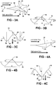
- the trough trailing edge 42 is recessed relative to the lobe trailing edge 40.
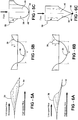
- Another variation is shown in Figures 5A-5C , and includes tabs 46 having curved apexes 48 having a terminal point 50 similar to the geometries shown in Figures 3A-4C .
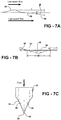
- Figure 6A-7C have triangular-like tabs 46 that come to sharp points at their apexes.
- the preferred lobe features such as shape and h/w ratio are distinct from prior art for lobed mixers in that the side-walls are substantially non-vertical (so as to avoid high concentrations of vorticity and mixing) and the h/w ratios are usually of order 1 or smaller, significantly lower than ratios of 4-6 characteristic of lobed mixers.
- Axial vorticity generated by this configuration was obtained using Reynolds-averaged Navier Stokes computations.
- contouring of the (lobe) trough edges coupled with the lobe feature allows and enhances radial flow in the base region, producing more circulation without increasing drag penalty.
- the lobe provides a means to direct a portion of the exit exhaust in the axial direction and adjust the effective area at the nozzle exit. In this way, the undulation of the nozzle edge expands the design space enabling optimal nozzle design to reduce thrust penalty.
Landscapes
- Engineering & Computer Science (AREA)
- Chemical & Material Sciences (AREA)
- Combustion & Propulsion (AREA)
- Mechanical Engineering (AREA)
- General Engineering & Computer Science (AREA)
- Structures Of Non-Positive Displacement Pumps (AREA)
- Control Of Turbines (AREA)
- Jet Pumps And Other Pumps (AREA)
- Turbine Rotor Nozzle Sealing (AREA)
Claims (14)
- Düse (12; 14), umfassend:eine ringförmige Wand (28), die einen Fluidflussdurchlass definiert und einen Basisabschnitt (30) und einen angrenzenden Austrittsabschnitt (32) beinhaltet, wobei der Austrittsabschnitt (32) Wellen (34) in einer im Allgemeinen radialen Richtung beinhaltet, die Lappen (36) und Mulden (38) bereitstellen, die jeweils Abströmkanten (40, 42) beinhalten, wobei die Muldenabströmkanten (42) von den Lappenabströmkanten (40) in einer im Allgemeinen axialen Richtung ausgespart sind, wobei die Lappenabströmkanten Spitzen (48) bilden, wobei die Spitzen an Laschen (46) bereitgestellt sind, und wobei sich Mulden (38) radial einwärts in einer axialen Richtung in Richtung der Muldenabströmkanten (42) erstrecken;wobei der Basisabschnitt (30) eine Kontur mit einer imaginären Fläche (S) beinhaltet, die sich axial in der Richtung der Kontur erstreckt, wobei sich die Lappen (36) radial auswärts der imaginären Fläche (S) erstrecken und sich die Mulden (38) radial einwärts der imaginären Fläche (S) erstrecken;wobei jeder Lappen (36) die gleiche Form wie jeder der anderen Lappen (36) aufweist und jede Mulde (38) die gleiche Form wie jede der anderen Mulden (38) aufweist;und dass die Mulden (38) von den Lappen (36) in der im Allgemeinen axialen Richtung ausgespart sind, wobei sich die Lappen (36) radial auswärts in einem Lappenwinkel erstrecken, der als der mittlere Lappenwinkel (36) in der axialen Richtung definiert ist, ungefähr zwischen 0 und 26 Grad;wobei die Lappen (36) radial von der imaginären Fläche (S) auf ungefähr einer Höhe beabstandet sind, wobei die Lappen (36) die imaginäre Fläche (S) brechen und eine Breite definieren, die als der Abstand zwischen Spitzen von benachbarten Lappen (36) definiert ist, wobei die Höhe geteilt durch die Breite ein maximales Verhältnis von 0,2 definiert;wobei eine axiale Kontur jedes Lappens (36) eine Kosinusform ist; undwobei die Lappen (36) und die Mulden (38) eine sinusförmige Umfangskontur bereitstellen.
- Düse nach Anspruch 1, wobei eine Ebene eine Achse der Düse beinhaltet, wobei eine der Spitzen (48) in der Ebene liegt, und wobei eine Kante der Lasche (46), die die eine der Spitzen (48) in einem Winkel relativ zu der Ebene beinhaltet, eine Laschenplattform bereitstellt.
- Düse nach Anspruch 1 oder 2, wobei die Muldenabströmkante (42) in der im Allgemeinen axialen Richtung eine bogenförmige Kontur bildet.
- Düse nach einem vorhergehenden Anspruch, wobei die Laschen (46) eine Laschenkontur in der im Allgemeinen axialen Richtung beinhalten, wobei sich die Laschen (46) radial einwärts nahe der Spitzen (48) erstrecken, um einen Laschenpenetrationswinkel relativ zu der Laschenkontur bereitzustellen.
- Düse nach Anspruch 4, wobei die Laschenkontur parabelförmig ist.
- Düse nach einem vorhergehenden Anspruch, wobei die Düse (14) 6 bis 12 Laschen (46) und 6 bis 12 Lappen (36) beinhaltet.
- Düse nach einem vorhergehenden Anspruch, wobei das Verhältnis von Höhe geteilt durch Breite 0,1 beträgt.
- Düse nach einem vorhergehenden Anspruch, wobei der Lappenwinkel 14 bis 18 Grad beträgt.
- Gasturbinentriebwerk, umfassend:eine Gebläseausströmdüse (12), die um eine Kernausströmdüse (14) angeordnet ist, und einen zentralen Körper (18), der innerhalb der Kernausströmdüse (14) positioniert ist;wobei eine der Düsen (12, 14) eine Düse nach einem vorhergehenden Anspruch ist.
- Gasturbinentriebwerk nach Anspruch 9, wobei die eine der Düsen die Kernausströmdüse (14) ist.
- Gasturbinentriebwerk nach Anspruch 10, wobei sich die Spitzen (48) über ein Schlussende der Gebläseausströmdüse (12) hinaus erstrecken.
- Gasturbinentriebwerk nach Anspruch 11, wobei die eine der Düsen die Gebläseausströmdüse (12) ist.
- Gasturbinentriebwerk nach Anspruch 12, wobei die andere Düse eine zweite ringförmige Wand (28) beinhaltet, die einen zweiten Fluidflussdurchlass definiert und einen zweiten Basisabschnitt (30) und einen zweiten angrenzenden Austrittsabschnitt (32) definiert, wobei der zweite Austrittsabschnitt (32) zweite Wellen (34) in der im Allgemeinen radialen Richtung beinhaltet, die zweite Lappen (36) und zweite Mulden (38) bereitstellen, die jeweils zweite Abströmkanten (40, 42) beinhalten, wobei eine der zweiten Lappen- und Muldenabströmkanten (40, 42) in der im Allgemeinen axialen Richtung von den anderen der zweiten Lappen- und Muldenabströmkanten (40, 42) ausgespart ist, wobei die anderen der zweiten Lappen- und Muldenabströmkanten (40, 42) zweite Spitzen (48) bilden, wobei die zweiten Spitzen (48) an zweiten Laschen (46) bereitgestellt sind, und wobei sich zweite Mulden (38) radial einwärts in einer axialen Richtung in Richtung der zweiten Muldenabströmkanten (42) erstrecken.
- Gasturbinentriebwerk nach Anspruch 13, wobei eine Anzahl der Laschen (46) und zweiten Laschen (46) gleich ist, wobei die Lappen (36) und zweiten Lappen (36) in radialer Ausrichtung zueinander sind.
Applications Claiming Priority (2)
| Application Number | Priority Date | Filing Date | Title |
|---|---|---|---|
| US11/200,616 US7543452B2 (en) | 2005-08-10 | 2005-08-10 | Serrated nozzle trailing edge for exhaust noise suppression |
| EP06254093.5A EP1752649B1 (de) | 2005-08-10 | 2006-08-04 | Gezackte Düsenabströmkante einer Gasturbine |
Related Parent Applications (3)
| Application Number | Title | Priority Date | Filing Date |
|---|---|---|---|
| EP06254093.5 Division | 2006-08-04 | ||
| EP06254093.5A Division EP1752649B1 (de) | 2005-08-10 | 2006-08-04 | Gezackte Düsenabströmkante einer Gasturbine |
| EP06254093.5A Division-Into EP1752649B1 (de) | 2005-08-10 | 2006-08-04 | Gezackte Düsenabströmkante einer Gasturbine |
Publications (3)
| Publication Number | Publication Date |
|---|---|
| EP2568151A2 EP2568151A2 (de) | 2013-03-13 |
| EP2568151A3 EP2568151A3 (de) | 2013-11-06 |
| EP2568151B1 true EP2568151B1 (de) | 2020-02-26 |
Family
ID=37027836
Family Applications (2)
| Application Number | Title | Priority Date | Filing Date |
|---|---|---|---|
| EP06254093.5A Active EP1752649B1 (de) | 2005-08-10 | 2006-08-04 | Gezackte Düsenabströmkante einer Gasturbine |
| EP12195123.0A Active EP2568151B1 (de) | 2005-08-10 | 2006-08-04 | Gezackte Düsenabströmkante einer Gasturbine |
Family Applications Before (1)
| Application Number | Title | Priority Date | Filing Date |
|---|---|---|---|
| EP06254093.5A Active EP1752649B1 (de) | 2005-08-10 | 2006-08-04 | Gezackte Düsenabströmkante einer Gasturbine |
Country Status (5)
| Country | Link |
|---|---|
| US (1) | US7543452B2 (de) |
| EP (2) | EP1752649B1 (de) |
| JP (1) | JP2007046598A (de) |
| CN (1) | CN1912372A (de) |
| CA (1) | CA2551929A1 (de) |
Families Citing this family (41)
| Publication number | Priority date | Publication date | Assignee | Title |
|---|---|---|---|---|
| US7305817B2 (en) * | 2004-02-09 | 2007-12-11 | General Electric Company | Sinuous chevron exhaust nozzle |
| US7377108B2 (en) * | 2004-04-09 | 2008-05-27 | The Boeing Company | Apparatus and method for reduction jet noise from single jets |
| GB0505246D0 (en) * | 2005-03-15 | 2005-04-20 | Rolls Royce Plc | Engine noise |
| FR2902837B1 (fr) * | 2006-06-26 | 2008-10-24 | Snecma Sa | Capot pour tuyere de turbomachine muni de motifs triangulaires a doubles sommets pour reduire le bruit de jet |
| US8015819B2 (en) * | 2006-09-29 | 2011-09-13 | The United States Of America As Represented By The Administrator Of The National Aeronautics And Space Administration | Wet active chevron nozzle for controllable jet noise reduction |
| US7963099B2 (en) * | 2007-05-21 | 2011-06-21 | General Electric Company | Fluted chevron exhaust nozzle |
| US7926285B2 (en) * | 2007-07-18 | 2011-04-19 | General Electric Company | Modular chevron exhaust nozzle |
| FR2921700A1 (fr) * | 2007-09-28 | 2009-04-03 | Snecma Sa | Capot pour tuyere de turbomachine a motifs a reduction de bruit de jet |
| FR2929334B1 (fr) * | 2008-03-31 | 2012-06-01 | Airbus France | Dispositif de reduction du bruit genere par reacteur d'aeronef a conduits de fluide coudes |
| FR2930972B1 (fr) * | 2008-05-07 | 2012-11-30 | Airbus France | Turbomachine a double flux pour aeronef a emission de bruit reduite |
| GB0820175D0 (en) * | 2008-11-05 | 2008-12-10 | Rolls Royce Plc | A gas turbine engine variable area exhuast nozzle |
| FR2945838B1 (fr) * | 2009-05-20 | 2014-06-13 | Snecma | Capot pour tuyere de turbomachine muni de motifs a ailettes laterales pour reduire le bruit de jet. |
| US9964070B2 (en) * | 2009-06-12 | 2018-05-08 | The Boeing Company | Gas turbine engine nozzle including housing having scalloped root regions |
| US8356468B2 (en) * | 2009-06-12 | 2013-01-22 | The Boeing Company | Gas turbine engine nozzle configurations |
| US8794902B1 (en) * | 2010-01-26 | 2014-08-05 | II Daniel K. Van Ness | System and method to improve the exhaust pressure across a RAM air turbine through secondary flow mixing |
| BR112012025460A2 (pt) * | 2010-04-09 | 2016-07-05 | Ihi Corp | bocal de fluxo de jato e motor a jato |
| US8635875B2 (en) | 2010-04-29 | 2014-01-28 | Pratt & Whitney Canada Corp. | Gas turbine engine exhaust mixer including circumferentially spaced-apart radial rows of tabs extending downstream on the radial walls, crests and troughs |
| FR2960028B1 (fr) * | 2010-05-12 | 2016-07-15 | Snecma | Dispositif pour attenuer le bruit emis par le jet d'un moteur de propulsion d'un aeronef. |
| US9435537B2 (en) | 2010-11-30 | 2016-09-06 | General Electric Company | System and method for premixer wake and vortex filling for enhanced flame-holding resistance |
| FR2986831A1 (fr) | 2012-02-10 | 2013-08-16 | Snecma | Procede pour definir la forme d'une tuyere convergente-divergente d'une turbomachine et tuyere convergente-divergente correspondante. |
| FR2986833B1 (fr) * | 2012-02-10 | 2017-05-19 | Snecma | Procede pour definir des chevrons dans un capot d'une tuyere de turbomachine et capot pour une tuyere de turbomachine correspondant |
| US9511873B2 (en) * | 2012-03-09 | 2016-12-06 | The Boeing Company | Noise-reducing engine nozzle system |
| US20170082063A1 (en) * | 2012-03-09 | 2017-03-23 | The Boeing Company | Engine nozzle system for shock-cell noise reduction |
| FR3008739B1 (fr) * | 2013-07-18 | 2017-03-24 | Snecma | Tuyere d'une turbomachine equipee de chevrons a face interne non axi-symetrique. |
| FR3010454B1 (fr) * | 2013-09-10 | 2024-02-16 | Snecma | Arriere corps de turboreacteur a flux melanges comportant un melangeur a lobes et des chevrons a surface interne non axisymetrique |
| US9869190B2 (en) | 2014-05-30 | 2018-01-16 | General Electric Company | Variable-pitch rotor with remote counterweights |
| US10072510B2 (en) | 2014-11-21 | 2018-09-11 | General Electric Company | Variable pitch fan for gas turbine engine and method of assembling the same |
| US10100653B2 (en) | 2015-10-08 | 2018-10-16 | General Electric Company | Variable pitch fan blade retention system |
| CN105781791A (zh) * | 2016-04-06 | 2016-07-20 | 西北工业大学 | 一种强化混合的脉动喷气用波瓣降噪引射器 |
| JP2017198498A (ja) * | 2016-04-26 | 2017-11-02 | 株式会社Soken | 流量測定装置 |
| CN106542046B (zh) * | 2016-09-29 | 2018-06-01 | 中国运载火箭技术研究院 | 一种扰流式涡破碎尾部减阻装置 |
| FR3070186B1 (fr) * | 2017-08-21 | 2021-06-11 | Safran Aircraft Engines | Tuyere secondaire modifiee acoustique |
| GB201818839D0 (en) | 2018-11-19 | 2019-01-02 | Cambridge Entpr Ltd | Foils with serrations |
| FR3095675B1 (fr) | 2019-05-03 | 2021-04-09 | Safran Aircraft Engines | Mélangeur à flux séparés de turbomachine |
| EP4286267A4 (de) * | 2021-02-02 | 2024-08-21 | Kim, Jung Gyu | Schubverbesserungsvorrichtung |
| US11674435B2 (en) | 2021-06-29 | 2023-06-13 | General Electric Company | Levered counterweight feathering system |
| US11795964B2 (en) | 2021-07-16 | 2023-10-24 | General Electric Company | Levered counterweight feathering system |
| CN114715416B (zh) * | 2022-03-22 | 2025-08-12 | 中国商用飞机有限责任公司北京民用飞机技术研究中心 | 一种航空涡扇发动机及外涵道喷口 |
| US11920539B1 (en) | 2022-10-12 | 2024-03-05 | General Electric Company | Gas turbine exhaust nozzle noise abatement |
| US12442532B2 (en) * | 2023-01-10 | 2025-10-14 | Pratt & Whitney Canada Corp. | Exhaust mixer with protrusions |
| CN119878390A (zh) * | 2025-01-14 | 2025-04-25 | 上海大学 | 一种基于内壁波纹的喷管减阻降噪结构 |
Family Cites Families (37)
| Publication number | Priority date | Publication date | Assignee | Title |
|---|---|---|---|---|
| US3161257A (en) * | 1959-05-01 | 1964-12-15 | Young Alec David | Jet pipe nozzle silencers |
| US3568792A (en) * | 1969-06-18 | 1971-03-09 | Rohr Corp | Sound-suppressing and thrust-reversing apparatus |
| FR2241695B1 (de) * | 1973-08-21 | 1978-03-17 | Bertin & Cie | |
| US4077206A (en) * | 1976-04-16 | 1978-03-07 | The Boeing Company | Gas turbine mixer apparatus for suppressing engine core noise and engine fan noise |
| US4149375A (en) * | 1976-11-29 | 1979-04-17 | United Technologies Corporation | Lobe mixer for gas turbine engine |
| US4302934A (en) * | 1979-11-01 | 1981-12-01 | United Technologies Corporation | Lobed mixer/inverter |
| GB2082259B (en) * | 1980-08-15 | 1984-03-07 | Rolls Royce | Exhaust flow mixers and nozzles |
| US4401269A (en) * | 1980-09-26 | 1983-08-30 | United Technologies Corporation | Lobe mixer for gas turbine engine |
| GB2119859A (en) * | 1982-05-06 | 1983-11-23 | Rolls Royce | Exhaust mixer for bypass gas turbine aeroengine |
| US4548034A (en) * | 1983-05-05 | 1985-10-22 | Rolls-Royce Limited | Bypass gas turbine aeroengines and exhaust mixers therefor |
| GB2146702B (en) * | 1983-09-14 | 1987-12-23 | Rolls Royce | Exhaust mixer for turbofan aeroengine |
| US4707899A (en) * | 1985-08-21 | 1987-11-24 | Morton Thiokol, Inc. | Method of making rocket motor extendible nozzle exit cone |
| CA1324999C (en) * | 1986-04-30 | 1993-12-07 | Walter M. Presz, Jr. | Bodies with reduced surface drag |
| US4850535A (en) * | 1988-03-16 | 1989-07-25 | Ivie Paul B | Variably convergent exhaust nozzle for a model ducted fan unit |
| FR2705737B1 (fr) * | 1993-05-28 | 1995-08-18 | Europ Propulsion | Tuyère de moteur-fusée à divergent échancré. |
| GB2289921A (en) | 1994-06-03 | 1995-12-06 | A E Harris Limited | Nozzle for turbofan aeroengines |
| US6082635A (en) * | 1996-06-12 | 2000-07-04 | The United States Of America As Represented By The Administrator Of The National Aeronautics And Space Administration | Undulated nozzle for enhanced exit area mixing |
| US6016651A (en) * | 1997-06-24 | 2000-01-25 | Sikorsky Aircraft Corporation | Multi-stage mixer/ejector for suppressing infrared radiation |
| US5992140A (en) * | 1997-06-24 | 1999-11-30 | Sikorsky Aircraft Corporation | Exhaust nozzle for suppressing infrared radiation |
| US6360528B1 (en) * | 1997-10-31 | 2002-03-26 | General Electric Company | Chevron exhaust nozzle for a gas turbine engine |
| US6314721B1 (en) * | 1998-09-04 | 2001-11-13 | United Technologies Corporation | Tabbed nozzle for jet noise suppression |
| US6487848B2 (en) * | 1998-11-06 | 2002-12-03 | United Technologies Corporation | Gas turbine engine jet noise suppressor |
| EP1141534B1 (de) * | 1999-01-04 | 2005-04-06 | Allison Advanced Development Company | Abgasmischvorrichtung und gerät mit einer solchen vorrichtung |
| US6578355B1 (en) * | 1999-03-05 | 2003-06-17 | Rolls-Royce Deutschland Ltd & Co Kg | Bloom mixer for a turbofan engine |
| US6640537B2 (en) * | 2000-12-18 | 2003-11-04 | Pratt & Whitney Canada Corp. | Aero-engine exhaust jet noise reduction assembly |
| GB0105349D0 (en) * | 2001-03-03 | 2001-04-18 | Rolls Royce Plc | Gas turbine engine exhaust nozzle |
| US6532729B2 (en) * | 2001-05-31 | 2003-03-18 | General Electric Company | Shelf truncated chevron exhaust nozzle for reduction of exhaust noise and infrared (IR) signature |
| AU2002351309A1 (en) * | 2001-12-07 | 2003-06-23 | Jack H. Anderson | Jet nozzle mixer |
| US6658839B2 (en) * | 2002-02-28 | 2003-12-09 | The Boeing Company | Convergent/divergent segmented exhaust nozzle |
| FR2855558B1 (fr) * | 2003-05-28 | 2005-07-15 | Snecma Moteurs | Tuyere de turbomachine a reduction de bruit |
| FR2857416B1 (fr) * | 2003-07-09 | 2007-05-25 | Snecma Moteurs | Dispositif de reduction du bruit de jet d'une turbomachine |
| US7093423B2 (en) * | 2004-01-20 | 2006-08-22 | General Electric Company | Methods and apparatus for operating gas turbine engines |
| US7305817B2 (en) * | 2004-02-09 | 2007-12-11 | General Electric Company | Sinuous chevron exhaust nozzle |
| US7114323B2 (en) * | 2004-03-05 | 2006-10-03 | United Technologies Corporation | Jet exhaust noise reduction system and method |
| US7246481B2 (en) * | 2004-03-26 | 2007-07-24 | General Electric Company | Methods and apparatus for operating gas turbine engines |
| FR2873166B1 (fr) * | 2004-07-13 | 2008-10-31 | Snecma Moteurs Sa | Tuyere de turbomachine a motifs a reduction de bruit de jet |
| US7578133B2 (en) * | 2005-03-28 | 2009-08-25 | United Technologies Corporation | Reduced radar cross section exhaust nozzle assembly |
-
2005
- 2005-08-10 US US11/200,616 patent/US7543452B2/en not_active Expired - Lifetime
-
2006
- 2006-07-06 CA CA002551929A patent/CA2551929A1/en not_active Abandoned
- 2006-08-01 JP JP2006209439A patent/JP2007046598A/ja active Pending
- 2006-08-04 EP EP06254093.5A patent/EP1752649B1/de active Active
- 2006-08-04 EP EP12195123.0A patent/EP2568151B1/de active Active
- 2006-08-10 CN CNA2006101148139A patent/CN1912372A/zh active Pending
Non-Patent Citations (1)
| Title |
|---|
| None * |
Also Published As
| Publication number | Publication date |
|---|---|
| CN1912372A (zh) | 2007-02-14 |
| CA2551929A1 (en) | 2007-02-10 |
| EP1752649A3 (de) | 2010-03-24 |
| US20070033922A1 (en) | 2007-02-15 |
| JP2007046598A (ja) | 2007-02-22 |
| US7543452B2 (en) | 2009-06-09 |
| EP2568151A2 (de) | 2013-03-13 |
| EP1752649B1 (de) | 2017-12-20 |
| EP1752649A2 (de) | 2007-02-14 |
| EP2568151A3 (de) | 2013-11-06 |
Similar Documents
| Publication | Publication Date | Title |
|---|---|---|
| EP2568151B1 (de) | Gezackte Düsenabströmkante einer Gasturbine | |
| EP1340901B1 (de) | Schubdüse mit gewelltem Rand zur Geräuschdämpfung | |
| EP1397586B1 (de) | Abgasströmungsführung zur reduktion von luftstrahllärm | |
| US6082635A (en) | Undulated nozzle for enhanced exit area mixing | |
| US5924632A (en) | Jet nozzle having centerbody for enhanced exit area mixing | |
| US6786037B2 (en) | Segmented mixing device having chevrons for exhaust noise reduction in jet engines | |
| JP4293573B2 (ja) | シェヴロン排気ノズル | |
| CA2728527C (en) | Duplex tab exhaust nozzle | |
| US6532729B2 (en) | Shelf truncated chevron exhaust nozzle for reduction of exhaust noise and infrared (IR) signature | |
| US7114323B2 (en) | Jet exhaust noise reduction system and method | |
| US9249755B2 (en) | Method for defining the shape of a turbomachine convergent-divergent nozzle, and corresponding convergent-divergent nozzle | |
| US7310939B2 (en) | Device for reducing the jet noise of a turbomachine | |
| EP0991861A1 (de) | Abgasdüse zur vermeidung von infrarotstrahlung | |
| CN112502853B (zh) | 喷管、配备该喷管的喷气发动机和喷气式飞机 | |
| US20180202391A1 (en) | Fan exhaust for a gas turbine engine | |
| US20160215727A1 (en) | Afterbody for a mixed-flow turbojet engine comprising a lobed mixer and chevrons with a non-axisymmetric inner surface | |
| US20230051249A1 (en) | Compressor blade | |
| EP1731747B1 (de) | Vorrichtung und Methode zur Reduktion des Luftstrahlaustrittslärms | |
| US11274632B2 (en) | Nozzle of a turbomachine provided with chevrons with a non-axisymmetric inner face | |
| CN110998080B (zh) | 改进的声学次级喷嘴 | |
| Seiner et al. | Undulated nozzle for enhanced exit area mixing | |
| Gutmark | Duplex tab exhaust nozzle |
Legal Events
| Date | Code | Title | Description |
|---|---|---|---|
| PUAI | Public reference made under article 153(3) epc to a published international application that has entered the european phase |
Free format text: ORIGINAL CODE: 0009012 |
|
| AC | Divisional application: reference to earlier application |
Ref document number: 1752649 Country of ref document: EP Kind code of ref document: P |
|
| AK | Designated contracting states |
Kind code of ref document: A2 Designated state(s): DE GB |
|
| RIN1 | Information on inventor provided before grant (corrected) |
Inventor name: REBA, RAMONS ANDRIS Inventor name: NARAYANAN, SATISH Inventor name: WAKE, BRIAN ERNEST Inventor name: MAEDER, THIERRY PASCAL |
|
| PUAL | Search report despatched |
Free format text: ORIGINAL CODE: 0009013 |
|
| AK | Designated contracting states |
Kind code of ref document: A3 Designated state(s): DE GB |
|
| RIC1 | Information provided on ipc code assigned before grant |
Ipc: F02K 1/46 20060101AFI20131002BHEP |
|
| 17P | Request for examination filed |
Effective date: 20140506 |
|
| RBV | Designated contracting states (corrected) |
Designated state(s): DE GB |
|
| RAP1 | Party data changed (applicant data changed or rights of an application transferred) |
Owner name: UNITED TECHNOLOGIES CORPORATION |
|
| STAA | Information on the status of an ep patent application or granted ep patent |
Free format text: STATUS: EXAMINATION IS IN PROGRESS |
|
| 17Q | First examination report despatched |
Effective date: 20170127 |
|
| GRAP | Despatch of communication of intention to grant a patent |
Free format text: ORIGINAL CODE: EPIDOSNIGR1 |
|
| STAA | Information on the status of an ep patent application or granted ep patent |
Free format text: STATUS: GRANT OF PATENT IS INTENDED |
|
| INTG | Intention to grant announced |
Effective date: 20190911 |
|
| GRAS | Grant fee paid |
Free format text: ORIGINAL CODE: EPIDOSNIGR3 |
|
| GRAA | (expected) grant |
Free format text: ORIGINAL CODE: 0009210 |
|
| STAA | Information on the status of an ep patent application or granted ep patent |
Free format text: STATUS: THE PATENT HAS BEEN GRANTED |
|
| AC | Divisional application: reference to earlier application |
Ref document number: 1752649 Country of ref document: EP Kind code of ref document: P |
|
| AK | Designated contracting states |
Kind code of ref document: B1 Designated state(s): DE GB |
|
| REG | Reference to a national code |
Ref country code: GB Ref legal event code: FG4D |
|
| REG | Reference to a national code |
Ref country code: DE Ref legal event code: R096 Ref document number: 602006059169 Country of ref document: DE |
|
| PGFP | Annual fee paid to national office [announced via postgrant information from national office to epo] |
Ref country code: DE Payment date: 20200721 Year of fee payment: 15 |
|
| REG | Reference to a national code |
Ref country code: DE Ref legal event code: R097 Ref document number: 602006059169 Country of ref document: DE |
|
| PLBE | No opposition filed within time limit |
Free format text: ORIGINAL CODE: 0009261 |
|
| STAA | Information on the status of an ep patent application or granted ep patent |
Free format text: STATUS: NO OPPOSITION FILED WITHIN TIME LIMIT |
|
| 26N | No opposition filed |
Effective date: 20201127 |
|
| REG | Reference to a national code |
Ref country code: DE Ref legal event code: R119 Ref document number: 602006059169 Country of ref document: DE |
|
| PG25 | Lapsed in a contracting state [announced via postgrant information from national office to epo] |
Ref country code: DE Free format text: LAPSE BECAUSE OF NON-PAYMENT OF DUE FEES Effective date: 20220301 |
|
| PGFP | Annual fee paid to national office [announced via postgrant information from national office to epo] |
Ref country code: GB Payment date: 20250724 Year of fee payment: 20 |