EP2568191A1 - Agencement d'embrayage et son procédé de commande - Google Patents
Agencement d'embrayage et son procédé de commande Download PDFInfo
- Publication number
- EP2568191A1 EP2568191A1 EP12182918A EP12182918A EP2568191A1 EP 2568191 A1 EP2568191 A1 EP 2568191A1 EP 12182918 A EP12182918 A EP 12182918A EP 12182918 A EP12182918 A EP 12182918A EP 2568191 A1 EP2568191 A1 EP 2568191A1
- Authority
- EP
- European Patent Office
- Prior art keywords
- clutch
- actuator
- closed position
- locking
- assembly
- Prior art date
- Legal status (The legal status is an assumption and is not a legal conclusion. Google has not performed a legal analysis and makes no representation as to the accuracy of the status listed.)
- Granted
Links
Images


Classifications
-
- F—MECHANICAL ENGINEERING; LIGHTING; HEATING; WEAPONS; BLASTING
- F16—ENGINEERING ELEMENTS AND UNITS; GENERAL MEASURES FOR PRODUCING AND MAINTAINING EFFECTIVE FUNCTIONING OF MACHINES OR INSTALLATIONS; THERMAL INSULATION IN GENERAL
- F16D—COUPLINGS FOR TRANSMITTING ROTATION; CLUTCHES; BRAKES
- F16D21/00—Systems comprising a plurality of actuated clutches
- F16D21/02—Systems comprising a plurality of actuated clutches for interconnecting three or more shafts or other transmission members in different ways
-
- B—PERFORMING OPERATIONS; TRANSPORTING
- B60—VEHICLES IN GENERAL
- B60K—ARRANGEMENT OR MOUNTING OF PROPULSION UNITS OR OF TRANSMISSIONS IN VEHICLES; ARRANGEMENT OR MOUNTING OF PLURAL DIVERSE PRIME-MOVERS IN VEHICLES; AUXILIARY DRIVES FOR VEHICLES; INSTRUMENTATION OR DASHBOARDS FOR VEHICLES; ARRANGEMENTS IN CONNECTION WITH COOLING, AIR INTAKE, GAS EXHAUST OR FUEL SUPPLY OF PROPULSION UNITS IN VEHICLES
- B60K1/00—Arrangement or mounting of electrical propulsion units
-
- B—PERFORMING OPERATIONS; TRANSPORTING
- B60—VEHICLES IN GENERAL
- B60K—ARRANGEMENT OR MOUNTING OF PROPULSION UNITS OR OF TRANSMISSIONS IN VEHICLES; ARRANGEMENT OR MOUNTING OF PLURAL DIVERSE PRIME-MOVERS IN VEHICLES; AUXILIARY DRIVES FOR VEHICLES; INSTRUMENTATION OR DASHBOARDS FOR VEHICLES; ARRANGEMENTS IN CONNECTION WITH COOLING, AIR INTAKE, GAS EXHAUST OR FUEL SUPPLY OF PROPULSION UNITS IN VEHICLES
- B60K17/00—Arrangement or mounting of transmissions in vehicles
- B60K17/04—Arrangement or mounting of transmissions in vehicles characterised by arrangement, location or kind of gearing
- B60K17/06—Arrangement or mounting of transmissions in vehicles characterised by arrangement, location or kind of gearing of change-speed gearing
- B60K17/08—Arrangement or mounting of transmissions in vehicles characterised by arrangement, location or kind of gearing of change-speed gearing of mechanical type
-
- F—MECHANICAL ENGINEERING; LIGHTING; HEATING; WEAPONS; BLASTING
- F16—ENGINEERING ELEMENTS AND UNITS; GENERAL MEASURES FOR PRODUCING AND MAINTAINING EFFECTIVE FUNCTIONING OF MACHINES OR INSTALLATIONS; THERMAL INSULATION IN GENERAL
- F16D—COUPLINGS FOR TRANSMITTING ROTATION; CLUTCHES; BRAKES
- F16D23/00—Details of mechanically-actuated clutches not specific for one distinct type
- F16D23/12—Mechanical clutch-actuating mechanisms arranged outside the clutch as such
-
- F—MECHANICAL ENGINEERING; LIGHTING; HEATING; WEAPONS; BLASTING
- F16—ENGINEERING ELEMENTS AND UNITS; GENERAL MEASURES FOR PRODUCING AND MAINTAINING EFFECTIVE FUNCTIONING OF MACHINES OR INSTALLATIONS; THERMAL INSULATION IN GENERAL
- F16D—COUPLINGS FOR TRANSMITTING ROTATION; CLUTCHES; BRAKES
- F16D2300/00—Special features for couplings or clutches
- F16D2300/14—Clutches which are normally open, i.e. not engaged in released state
-
- Y—GENERAL TAGGING OF NEW TECHNOLOGICAL DEVELOPMENTS; GENERAL TAGGING OF CROSS-SECTIONAL TECHNOLOGIES SPANNING OVER SEVERAL SECTIONS OF THE IPC; TECHNICAL SUBJECTS COVERED BY FORMER USPC CROSS-REFERENCE ART COLLECTIONS [XRACs] AND DIGESTS
- Y10—TECHNICAL SUBJECTS COVERED BY FORMER USPC
- Y10T—TECHNICAL SUBJECTS COVERED BY FORMER US CLASSIFICATION
- Y10T74/00—Machine element or mechanism
- Y10T74/19—Gearing
- Y10T74/19019—Plural power paths from prime mover
-
- Y—GENERAL TAGGING OF NEW TECHNOLOGICAL DEVELOPMENTS; GENERAL TAGGING OF CROSS-SECTIONAL TECHNOLOGIES SPANNING OVER SEVERAL SECTIONS OF THE IPC; TECHNICAL SUBJECTS COVERED BY FORMER USPC CROSS-REFERENCE ART COLLECTIONS [XRACs] AND DIGESTS
- Y10—TECHNICAL SUBJECTS COVERED BY FORMER USPC
- Y10T—TECHNICAL SUBJECTS COVERED BY FORMER US CLASSIFICATION
- Y10T74/00—Machine element or mechanism
- Y10T74/19—Gearing
- Y10T74/19219—Interchangeably locked
Definitions
- the present invention relates to a clutch assembly for a motor vehicle powertrain, wherein the clutch assembly comprises a first and a second clutch, which are formed as normally open clutches, wherein the first clutch is actuated by means of a first actuator assembly from an open to a closed position and wherein the second clutch is operable from a open position to a closed position by means of a second actuator assembly, and wherein the clutch assembly includes a locking means for locking a clutch in the closed position.
- Such a coupling arrangement is from the document DE 199 17 724 A1 known.
- This document discloses for the two clutches each have their own locking device, which are operated simultaneously to set up a parking lock function to block the transmission at a standstill.
- Clutch arrangements of the type mentioned above can be used, for example, as a clutch assembly in dual-clutch transmissions, wherein the clutch assembly between a drive motor and a multi-speed step transmission is arranged, and wherein the step transmission in this case has two partial transmissions.
- Each partial transmission are associated with different gears, wherein the one sub-transmission usually the even gear stages and the other sub-transmission are usually associated with the odd gear ratios.
- a clutch assembly of the type mentioned also for a drive train can be used, in which the drive motor is formed by an electric motor and in which the transmission has only two gear ratios.
- the clutch assembly is used to switch either the one gear stage or the other gear stage in the power flow towards a differential of a driven axle.
- the clutches are preferably designed as friction clutches, in particular as wet-running multi-plate clutches.
- the friction clutches can also be designed as dry friction clutches.
- the two friction clutches can be operated overlapping to perform gear changes under load can.
- Such friction clutches are usually actuated automatically by means of actuator arrangements.
- high safety requirements are to be met, since a simultaneous closing of both clutches can lead to a blockage of the transmission and thus to a blockage of a driven wheel.
- Friction clutches of this type can be designed either as normally closed or normally open friction clutches.
- Normally closed friction clutches are generally pressed by means of a mechanical spring arrangement in the closed position and opened by means of the actuator assembly.
- Normally open friction clutches for example, are biased by means of a mechanical spring arrangement into an open position and are moved by means of an actuator assembly in the closed position.
- a drive train for a motor vehicle comprising a drive motor and a multi-speed step transmission, which has a first and a second partial transmission, which are switchable by means of a clutch assembly of the type described above in the power flow and whose Outputs are connected to a driven axle, wherein the first clutch can switch the first partial transmission in the power flow and wherein the second clutch can switch the second partial transmission in the power flow, and wherein the clutches for performing a gear change are overlapping operable.
- the above object is achieved by a method for driving a clutch assembly, in particular a clutch assembly of the type described above, wherein the clutch assembly comprises a first and a second clutch, which are formed as normally open clutches, wherein the first clutch by means of a first actuator assembly an open position is operable to a closed position, and wherein the second clutch is actuated by means of a second actuator assembly from an open position to a closed position, and wherein only the second clutch by means of a locking device in the closed position is lockable, whereas the first clutch in the closed position is not lockable, so that the first actuator assembly must be powered to hold the first clutch in the closed position.
- the clutch assembly comprises a first and a second clutch, which are formed as normally open clutches, wherein the first clutch by means of a first actuator assembly an open position is operable to a closed position, and wherein the second clutch is actuated by means of a second actuator assembly from an open position to a closed position, and wherein only the second clutch by means of a locking device in
- the two clutches are preferably designed as friction clutches, in particular as wet-running multi-plate clutches.
- the friction clutches can also be designed as dry friction clutches.
- the actuator assemblies can each be designed as hydraulic actuator arrangements with a piston / cylinder arrangement.
- the actuator assemblies may also be formed by an electric motor or electromagnetically.
- the locking device is preferably a mechanical locking device, wherein the locking position is such a position in which the second clutch can transmit the maximum allowable torque.
- the locking position is preferably a self-holding position, which is preferably held by mechanical spring force during ArretsammlungsShes. Furthermore, the locking position can preferably be held without the second actuator assembly is to supply energy.
- Safety-related aspects may essentially relate to the activation of the first clutch, depending on the respective state of the second clutch (open, closed or in the locking position).
- the second clutch may preferably be moved between the open position and a closed position without establishing the detent position in which the maximum moment is transferable. Therefore, load circuits with overlapping operation of the two clutches can be performed without restriction without using the lock function.
- the first and the second clutch can be used in particular for connecting two rotatable components, in particular for connecting two shafts or for connecting a shaft to a loose wheel, which is mounted on this shaft.
- the locking device can act directly on the second clutch, even if the second actuator arrangement is not activated.
- a mechanical spring arrangement is arranged between the locking device and the second clutch, such as a plate or ring spring.
- the mechanical spring arrangement it is possible to move the second clutch against the spring action from the open to the closed position.
- This function can be used, for example, to set up the locking function.
- the mechanical spring assembly may also serve to bias the second friction clutch generally to the open position so that the second clutch is always open when disengaged from the locking position and when no actuator force is applied by the second actuator assembly.
- the second actuator assembly for establishing the closed position of the second clutch from a first actuator position in a forward direction in a second actuator position is movable, wherein the locking device is formed so that the second actuator assembly for locking the second clutch in the Moves forward beyond the second actuator position in a third actuator position.
- the mechanical spring arrangement is elastically deformed.
- the second clutch is closed both in the second actuator position and in the third actuator position.
- the locking position may be established.
- the third actuator position serves only as an intermediate position for establishing the locking position.
- the fourth position is thus the locking position in which the second clutch is closed and in which no force has to be exerted by the second actuator assembly for this purpose.
- the fourth position may be substantially equal to the second actuator position, but is preferably in the forward direction of the actuator movement seen behind the second actuator position, hence between the second and the third actuator position.
- the lock is released by the second actuator assembly is again moved in the forward direction, so that a release of the mechanical lock is simplified.
- the locking device can also easily establish a locking position (for example by means of a spring-biased pin which presses into a groove of a pressing part of the locking device), from which a return (in the backward direction) is also possible, without first moving again to initiate the forward direction.
- the second partial transmission, to which the second clutch is assigned has the gear ratio which is most frequently used when driving the vehicle.
- the locking device can be used for a high proportion of the driving operation, so that a high efficiency of the drive train can be achieved.
- the second clutch can consequently be assigned to that partial transmission which has the highest Gear ratio (in a 7-speed transmission consequently the gear stage 7, in a 6-speed manual transmission consequently the gear stage 6, etc.).
- the drive motor is an electric motor, wherein each of the two partial transmissions has exactly one forward gear stage and wherein the higher forward gear stage is set up by the second partial transmission.
- the drive train which is used for example for a pure electric vehicle or for a hybrid vehicle
- the drive train is designed as a range extender
- the second gear is used for the vast majority of driving.
- the first gear is usually used here only in athletic accelerations or on large gradients.
- the first clutch is monitored as to whether the first clutch is being moved or driven in the closing direction and a safety measure is initiated, when the first clutch is moved or driven in the closing direction.
- the first clutch may not be closed, otherwise tension conditions may occur in the driveline.
- a safety measure can be initiated, such as a "reset" of a control unit or the like, which usually automatically leads to the first actuator assembly is no longer supplied with energy, so that the first clutch opens automatically (due to their characteristics as a "normally open” or “normally open” clutch.
- gear changes can be performed under load without interruption of traction.
- a safety measure can be initiated, which preferably includes that a control unit undergoes a "reset". As a result, the first clutch is opened, and / or it is prevented that the second clutch moves in the locking position.
- FIG. 1 A first embodiment of a drive train according to the invention is in Fig. 1 generally designated 10.
- the drive train 10 includes a drive motor 12 in the form of an electric motor. Furthermore, the drive train 10 has a transmission 14, which in the present case is designed as a 2-speed transmission. The transmission 14 is power shiftable.
- the differential 16 which distributes drive power to two drive shafts 18L, 18R of a driven axle 17 of a motor vehicle.
- the differential 16 may be a mechanical differential (bevel gear differential, etc.), but may also be a differential formed by two friction clutches.
- the motor 12 is arranged coaxially with one of the drive shafts (here 18R) and has a motor shaft designed as a hollow shaft.
- the motor shaft is concentrically arranged around the drive shaft 18R and connected via a drive constant gear 20 with an intermediate shaft 22.
- the intermediate shaft 22 forms an input shaft for the transmission 14.
- the transmission 14 has a first partial transmission in the form of a first gear set 24 and a second partial transmission in the form of a second gear set 26.
- the first gear set 24 has a first idler gear 28, which is rotatably mounted on the intermediate shaft 22.
- the second gear set 26 has a second loose wheel 30, which is rotatably mounted on the intermediate shaft 22. Fixed gears engaged with the loosening wheels 28, 30 are connected to an input member of the differential 16.
- the powertrain 10 further includes a clutch assembly 34 having a first friction clutch 36 and a second friction clutch 38.
- the first friction clutch 36 serves to switch the first gear set 24 into the power flow.
- the second clutch 38 serves to switch the second gear wheel set 26 into the power flow.
- the couplings 36, 38 are each designed to either separate the idler gear 28, 30 associated therewith from the intermediate shaft 22 or to connect to it.
- the clutches 36, 38 are designed as power shift clutches, in the present case as wet-running multi-plate clutches.
- the respective input members of the clutches 36, 38 are fixedly connected to the intermediate shaft 22.
- the output members of the clutches 36, 38 are connected to the respective idler gears 38, 30.
- a first actuator arrangement 40 is used to actuate the first clutch 36.
- a second actuator arrangement 42 serves to actuate the second clutch 38.
- the actuator arrangements 40, 42 can be actuated independently of one another. In particular, it is possible to use the couplings by means of the actuator arrangements 40, 42 to operate overlapping, in order to be able to perform gear changes under load and without interruption of traction.
- the two clutches 36, 38 are each designed as normally open (“normally open”) couplings. That is, the clutches 36, 38 are biased, for example, to their open position. Only by supplying energy to the respective actuator assemblies 40, 42 and the application of an axial force on the clutches 36, 38 can transmit these torques. When the actuator assemblies 40, 42 are de-energized, the clutches 36, 38 usually open automatically.
- the second clutch 38 is associated with the second gear stage 2 of the transmission 14, thus that gear stage, which is predominantly used when driving the motor vehicle.
- the second coupling 38 is associated with a locking device 44, which in Fig. 1 is indicated schematically. This makes it possible to lock the second clutch 38 in a torque transmitting position, such that the second actuator 42 can be de-energized.
- the locking device 44 is preferably formed self-holding.
- the first clutch 36 has no locking device, so that when the first actuator assembly 40 no energy is supplied, the first clutch 36 always opens automatically.
- the locking device 44 is provided between the second actuator assembly 42 and the second clutch 38. Further, between the locking device 44 and the second clutch 38 is a mechanical spring arrangement 46 arranged.
- the spring assembly 46 may be configured to bias the second clutch 38 in the opening direction. Further, the spring assembly 46 is arranged and configured so that the second actuator assembly 42 can be further overdriven relative to a closed position of the second clutch 38 to establish the locking position of the actuator assembly 42 and the second clutch 38, as will be described below ,
- FIG. 2 an alternative embodiment of a drive train 10 'is shown. This corresponds in terms of design and operation generally the drive train 10 of Fig. 1 , The same elements are therefore identified by the same reference numerals. The following section essentially explains the differences.
- a drive motor 12 is flanged in the form of an electric motor from the outside to a housing 48 of the transmission 14.
- a motor shaft extends into the transmission housing 48 and is rotatably connected to a rotatably mounted in the transmission housing 48 input shaft 50 which is formed as a hollow shaft.
- the two gear sets 24, 26 each have a fixed gear which is connected to the input shaft 50.
- the intermediate shaft 22 is arranged parallel to the input shaft 50.
- the idler gears 28, 30 are rotatably mounted.
- the two clutches 36, 38 are arranged concentrically with the intermediate shaft 22 and can be actuated by means of the actuator arrangements 40, 42.
- a parking brake assembly P is disposed on the intermediate shaft 22.
- final drive including a fixed wheel connected to the intermediate shaft 22 and a wheel connected to an input member of the differential 16.
- the characteristic curve runs substantially linearly and applies both to the opening and to the closing of the first friction clutch 36.
- the characteristic curve established for the second clutch 38 is shown in solid lines and includes a linear portion from the starting point s 0 to a first value s 1 , from which the second clutch is closed and / or can transmit its maximum torque (closed position). In load circuits with overlapping actuation of the first clutch 36 and the second clutch 38, the second clutch 38 is moved substantially within this characteristic section.
- the second actuator assembly 42 is moved in the forward direction beyond the path s 1 , up to s 3 . Subsequently, the clutch is preferably pushed back automatically by the force of the spring assembly 46, in a position s 2 , preferably lies between the two positions s 1 and s 3 . In this position, the second actuator assembly 42 and the second clutch 38 is locked.
- the second actuator 42 is again activated, so that the actuator 42 is moved from the locking position s 2 again in the suppression position s 3 , from which the actuator 42 then back first to the position s 1 and then to the position s 0 arrives.
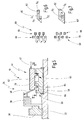
- FIG. 5 an embodiment of a clutch assembly 34 of the drive train 10 is shown in fragmentary form, wherein the same elements as in the embodiment of Fig. 1 are provided with the same reference numerals.
- the locking device 44 has a pressure member 56 which is movable in the axial direction and which is arranged between the second actuator arrangement 42 and the spring arrangement 46.
- the locking device 44 further includes a link member 58 which is mounted in the axial direction substantially immovably on the intermediate shaft 22, but rotatably relative to the intermediate shaft 22nd
- the link member 58 has a slotted guide 60, into which a driver such as a pin 62 of the pressure member 56 protrudes.
- the pressing member 56 includes a first gear 64
- the link member 58 includes a second gear 66, which can set a mechanical lock.
- the mechanical lock 68 and the slide guide 60 are in Fig. 6 shown in more detail.
- the slide guide 60 is approximately L-shaped in plan view and includes a first guide channel, within which the pin 62 is movable from the position s 0 to the position s 1 .
- the first guide channel is axially aligned.
- the slide guide 60 includes a second guide channel, within which the pin 62 is movable from the position s 3 to the position s 2 .
- the second guide channel is substantially aligned axially.
- the two guide channels are connected to each other via a substantially radially, preferably obliquely oriented further guide channel to move the guide pin from the position s 1 to position s 3 .
- the pressing member 56 and the guide member 58 rotate.
- the mechanical lock 68 is designed such that upon displacement of the pin 62 from s 0 to s 1, the first toothing 64 is guided axially through the second toothing 66. Due to the relative rotation of s 1 to s 3 , the first toothing 64 comes into alignment with the second toothing 66, so that in the position s 2, the first toothing 64 abuts the second toothing 66 in the axial direction, whereby the locking position is established. This is in Fig. 6 shown dashed on the left side. In this position, the second actuator 42 can be switched off, so that the first gear 64 is pressed by the spring assembly 46 against the second gear 66.
- the second actuator 42 is again deflected against the force of the spring assembly 46, so that the pin 62 passes from the position s 2 to position s 3 and from there to position s 1 and s 0 can pass.
- the pressure member 56 and the link member 58 may be biased against each other in the circumferential direction.
- FIG. 7 an alternative embodiment of such a slotted guide is shown at 60 '.
- the link guide 60 ' is formed as a heart-shaped gate and has a first guide portion within which the pin 62 is guided from the position s 0 to the position s 2 , and a second - separate - Guide section, within which the pin 62 is guided from the locking position s 2 back to the position s 0 .
- FIG Fig. 8 Another embodiment of a locking device 60 'is shown in FIG Fig. 8 shown.
- an actuator force of the second actuator arrangement 42 ' acts on a pressure element 56', which, as in the above embodiments, is coupled to the second clutch 38 via a spring arrangement.
- the pressure member 56 ' is linearly guided on a guide part 58', which, however, does not necessarily have to have a slotted guide.
- the pressure member On the outer circumference, the pressure member has a radial locking groove 70, into which a locking pin 72 can engage, which is guided displaceably in the radial direction on an unspecified housing.
- a locking spring 74 presses the locking pin 72 against the pressure member 56 '.
- the positions s 0 , s 1 and s 2 and s 3 are entered whose functions correspond to those of the above embodiment. Starting from s 0 , the locking position is reached via s 1 in the forward direction in the position s 2 / s 3 . This position is achievable without having to perform an overpressure as in the embodiment of Fig. 5-7 , Accordingly, the locking position s 2 / s 3 can be solved without first moving in the forward direction is required.
Landscapes
- Engineering & Computer Science (AREA)
- General Engineering & Computer Science (AREA)
- Mechanical Engineering (AREA)
- Chemical & Material Sciences (AREA)
- Combustion & Propulsion (AREA)
- Transportation (AREA)
- Mechanical Operated Clutches (AREA)
- Hydraulic Clutches, Magnetic Clutches, Fluid Clutches, And Fluid Joints (AREA)
Applications Claiming Priority (1)
| Application Number | Priority Date | Filing Date | Title |
|---|---|---|---|
| DE102011113279.5A DE102011113279B4 (de) | 2011-09-06 | 2011-09-06 | Kupplungsanordnung und Verfahren zu deren Ansteuerung |
Publications (2)
| Publication Number | Publication Date |
|---|---|
| EP2568191A1 true EP2568191A1 (fr) | 2013-03-13 |
| EP2568191B1 EP2568191B1 (fr) | 2015-04-08 |
Family
ID=46758657
Family Applications (1)
| Application Number | Title | Priority Date | Filing Date |
|---|---|---|---|
| EP12182918.8A Active EP2568191B1 (fr) | 2011-09-06 | 2012-09-04 | Agencement d'embrayage et son procédé de commande |
Country Status (4)
| Country | Link |
|---|---|
| US (1) | US8984989B2 (fr) |
| EP (1) | EP2568191B1 (fr) |
| CN (1) | CN103047313B (fr) |
| DE (1) | DE102011113279B4 (fr) |
Cited By (1)
| Publication number | Priority date | Publication date | Assignee | Title |
|---|---|---|---|---|
| FR3077536A1 (fr) * | 2018-02-05 | 2019-08-09 | Valeo Embrayages | Dispositif de transmission a deux vitesses pour vehicule electrique |
Families Citing this family (5)
| Publication number | Priority date | Publication date | Assignee | Title |
|---|---|---|---|---|
| DE102015226227B4 (de) | 2015-12-21 | 2022-03-10 | Schaeffler Technologies AG & Co. KG | Doppelkupplung |
| TWI615294B (zh) | 2016-01-15 | 2018-02-21 | 財團法人工業技術研究院 | 具有雙離合器的電動車用兩速變速箱 |
| DE102016205061B4 (de) | 2016-03-24 | 2020-07-09 | Audi Ag | Antriebseinrichtung für ein Kraftfahrzeug |
| US10527111B2 (en) | 2016-10-24 | 2020-01-07 | Deere & Company | Work vehicle drive assembly with electric motor overspeed protection |
| FR3092793B1 (fr) * | 2019-02-15 | 2021-01-29 | Valeo Embrayages | Dispositif de transmission de couple pour un véhicule automobile |
Citations (5)
| Publication number | Priority date | Publication date | Assignee | Title |
|---|---|---|---|---|
| US2991863A (en) * | 1959-06-19 | 1961-07-11 | Int Harvester Co | Hand operated control mechanism for a plurality of clutch assemblies |
| DE19917724A1 (de) | 1999-04-20 | 2000-11-16 | Getrag Getriebe Zahnrad | Antriebstrang für ein Kraftfahrzeug |
| EP1400715A1 (fr) * | 2002-09-20 | 2004-03-24 | ZF Sachs AG | Système d'embrayage et dispositif de retenue pour retenir au moins un embrayage dans un condition engagé |
| DE10316793A1 (de) * | 2002-11-12 | 2004-05-27 | Zf Sachs Ag | Einrückersystem für eine Reibungskupplung |
| DE102007023955A1 (de) | 2007-05-23 | 2008-11-27 | Zf Friedrichshafen Ag | Vorrichtung zum Betätigen eines Schaltelementes einer Getriebeeinrichtung |
Family Cites Families (7)
| Publication number | Priority date | Publication date | Assignee | Title |
|---|---|---|---|---|
| US3419118A (en) * | 1966-12-01 | 1968-12-31 | Borg Warner | Electromagnetically actuated clutch |
| DE3623142A1 (de) * | 1986-07-09 | 1988-01-28 | Hurth Masch Zahnrad Carl | Schaltbare reibungskupplung fuer zahnradgetriebe |
| DE3842722C1 (en) * | 1988-12-19 | 1990-06-13 | Bayerische Motoren Werke Ag, 8000 Muenchen, De | Actuating device for a friction clutch arranged in the drive train of a motor vehicle |
| DE10238117B4 (de) * | 2002-08-21 | 2013-06-13 | Volkswagen Ag | Einrückeranordnung zur Erzeugung einer Einrückkraft für eine Reibungskupplung |
| DE102007007759A1 (de) * | 2006-11-17 | 2008-05-21 | Borgwarner Inc., Auburn Hills | Kupplungsaktuatorik mit Bremseinrichtung und Kupplung mit einer solchen Kupplungsaktuatorik |
| DE102007010307B3 (de) * | 2007-02-22 | 2008-06-05 | Hoerbiger Synchrontechnik Gmbh & Co. Kg | Schaltkupplungsanordnung |
| DE102008013054B4 (de) * | 2008-03-06 | 2010-04-22 | Getrag Getriebe- Und Zahnradfabrik Hermann Hagenmeyer Gmbh & Cie Kg | Stellmechanismus zum Ein- und Ausrücken einer Trennkupplung mit drehbarem Kurvensegment |
-
2011
- 2011-09-06 DE DE102011113279.5A patent/DE102011113279B4/de active Active
-
2012
- 2012-09-04 EP EP12182918.8A patent/EP2568191B1/fr active Active
- 2012-09-05 US US13/604,567 patent/US8984989B2/en active Active
- 2012-09-06 CN CN201210529773.XA patent/CN103047313B/zh active Active
Patent Citations (5)
| Publication number | Priority date | Publication date | Assignee | Title |
|---|---|---|---|---|
| US2991863A (en) * | 1959-06-19 | 1961-07-11 | Int Harvester Co | Hand operated control mechanism for a plurality of clutch assemblies |
| DE19917724A1 (de) | 1999-04-20 | 2000-11-16 | Getrag Getriebe Zahnrad | Antriebstrang für ein Kraftfahrzeug |
| EP1400715A1 (fr) * | 2002-09-20 | 2004-03-24 | ZF Sachs AG | Système d'embrayage et dispositif de retenue pour retenir au moins un embrayage dans un condition engagé |
| DE10316793A1 (de) * | 2002-11-12 | 2004-05-27 | Zf Sachs Ag | Einrückersystem für eine Reibungskupplung |
| DE102007023955A1 (de) | 2007-05-23 | 2008-11-27 | Zf Friedrichshafen Ag | Vorrichtung zum Betätigen eines Schaltelementes einer Getriebeeinrichtung |
Cited By (1)
| Publication number | Priority date | Publication date | Assignee | Title |
|---|---|---|---|---|
| FR3077536A1 (fr) * | 2018-02-05 | 2019-08-09 | Valeo Embrayages | Dispositif de transmission a deux vitesses pour vehicule electrique |
Also Published As
| Publication number | Publication date |
|---|---|
| CN103047313A (zh) | 2013-04-17 |
| CN103047313B (zh) | 2016-09-14 |
| US8984989B2 (en) | 2015-03-24 |
| US20130055851A1 (en) | 2013-03-07 |
| DE102011113279A1 (de) | 2013-03-07 |
| EP2568191B1 (fr) | 2015-04-08 |
| DE102011113279B4 (de) | 2014-08-07 |
Similar Documents
| Publication | Publication Date | Title |
|---|---|---|
| DE102012016235B4 (de) | Aktuatoranordnung für einen Antriebsstrang | |
| EP2568192B1 (fr) | Agencement d'embrayage, faisceau d'entraînement de véhicule automobile et procédé d'actionnement d'embrayage | |
| EP2664826B1 (fr) | Agencement d'actionneur pour une transmission de véhicule automobile | |
| DE4400701C2 (de) | Übertragungsvorrichtung zur Übertragung einer Motorleistung auf Antriebsräder eines Fahrzeuges | |
| DE102013224853B4 (de) | Verfahren zur Schaltsteuerung eines automatisierten Schaltgetriebes | |
| EP2927540B1 (fr) | Système de frein de stationnement pour une boîte de vitesses de véhicule et boîte de vitesses en étant équipée | |
| DE102012022635B4 (de) | Schaltungsanordnung mit Parksperre und Verfahren zu deren Betätigung | |
| EP2568191B1 (fr) | Agencement d'embrayage et son procédé de commande | |
| DE102012015863A1 (de) | Stufengetriebe für ein Kraftfahrzeug | |
| DE10034746A1 (de) | Schaltgetriebe für ein Fahrzeug | |
| DE102012206936A1 (de) | Hybridgetriebe | |
| DE102011017695A1 (de) | Vorrichtung zum Betätigen einer Getriebeeinrichtung mit mehreren elektrohydraulischen betätigbaren reib- und formschlüssigen Schaltelementen | |
| DE112011104889T5 (de) | Linearbetätigung für wählbar festgelegte Zahnräder | |
| WO2010139557A1 (fr) | Ensemble comprenant au moins un embrayage à crabots | |
| DE102015211367B4 (de) | Automatgetriebe eines Fahrzeuges mit einer Zentralsynchronisierungseinrichtung und Verfahren zum Betreiben eines Automatgetriebes | |
| AT5363U1 (de) | Verteilergetriebe mit steuerbarer reibungskupplung | |
| DE102004052869A1 (de) | Parkbremsmechanismus für ein integriertes Schalt- und Verteilergetriebe | |
| DE102017130920B4 (de) | Aktuatoranordnung für einen Kraftfahrzeugantriebsstrang und Verfahren zu dessen Betreiben | |
| DE102019108875A1 (de) | Doppelkupplungs-Aktuator und Antriebsbaugruppe mit einem solchen Aktuator | |
| EP2455249B1 (fr) | Agencement d'entraînement pour véhicules automobiles commandés temporairement par les quatre roues | |
| DE102015108031A1 (de) | Kraftfahrzeug-Antriebsstrang und Ansteuerverfahren | |
| EP3908765A1 (fr) | Arrangement actionneur pour un arrangement d'accouplement pour une chaîne cinématique d'un véhicule automobile | |
| DE2857337C2 (de) | Automatisches Getriebe mit paralleler Eingangs- und Ausgangswelle | |
| DE1211077B (de) | Umlaufraederwechselgetriebe, insbesondere fuer Kraftfahrzeuge | |
| DE102015011405A1 (de) | Getriebeeinrichtung für ein Kraftfahrzeug |
Legal Events
| Date | Code | Title | Description |
|---|---|---|---|
| PUAI | Public reference made under article 153(3) epc to a published international application that has entered the european phase |
Free format text: ORIGINAL CODE: 0009012 |
|
| AK | Designated contracting states |
Kind code of ref document: A1 Designated state(s): AL AT BE BG CH CY CZ DE DK EE ES FI FR GB GR HR HU IE IS IT LI LT LU LV MC MK MT NL NO PL PT RO RS SE SI SK SM TR |
|
| AX | Request for extension of the european patent |
Extension state: BA ME |
|
| 17P | Request for examination filed |
Effective date: 20130816 |
|
| RBV | Designated contracting states (corrected) |
Designated state(s): AL AT BE BG CH CY CZ DE DK EE ES FI FR GB GR HR HU IE IS IT LI LT LU LV MC MK MT NL NO PL PT RO RS SE SI SK SM TR |
|
| GRAP | Despatch of communication of intention to grant a patent |
Free format text: ORIGINAL CODE: EPIDOSNIGR1 |
|
| INTG | Intention to grant announced |
Effective date: 20141029 |
|
| GRAS | Grant fee paid |
Free format text: ORIGINAL CODE: EPIDOSNIGR3 |
|
| GRAA | (expected) grant |
Free format text: ORIGINAL CODE: 0009210 |
|
| AK | Designated contracting states |
Kind code of ref document: B1 Designated state(s): AL AT BE BG CH CY CZ DE DK EE ES FI FR GB GR HR HU IE IS IT LI LT LU LV MC MK MT NL NO PL PT RO RS SE SI SK SM TR |
|
| REG | Reference to a national code |
Ref country code: GB Ref legal event code: FG4D Free format text: NOT ENGLISH |
|
| REG | Reference to a national code |
Ref country code: CH Ref legal event code: EP |
|
| REG | Reference to a national code |
Ref country code: IE Ref legal event code: FG4D Free format text: LANGUAGE OF EP DOCUMENT: GERMAN |
|
| REG | Reference to a national code |
Ref country code: AT Ref legal event code: REF Ref document number: 720830 Country of ref document: AT Kind code of ref document: T Effective date: 20150515 |
|
| REG | Reference to a national code |
Ref country code: DE Ref legal event code: R096 Ref document number: 502012002774 Country of ref document: DE Effective date: 20150521 |
|
| REG | Reference to a national code |
Ref country code: NL Ref legal event code: VDEP Effective date: 20150408 |
|
| REG | Reference to a national code |
Ref country code: LT Ref legal event code: MG4D |
|
| PG25 | Lapsed in a contracting state [announced via postgrant information from national office to epo] |
Ref country code: NL Free format text: LAPSE BECAUSE OF FAILURE TO SUBMIT A TRANSLATION OF THE DESCRIPTION OR TO PAY THE FEE WITHIN THE PRESCRIBED TIME-LIMIT Effective date: 20150408 |
|
| PG25 | Lapsed in a contracting state [announced via postgrant information from national office to epo] |
Ref country code: FI Free format text: LAPSE BECAUSE OF FAILURE TO SUBMIT A TRANSLATION OF THE DESCRIPTION OR TO PAY THE FEE WITHIN THE PRESCRIBED TIME-LIMIT Effective date: 20150408 Ref country code: LT Free format text: LAPSE BECAUSE OF FAILURE TO SUBMIT A TRANSLATION OF THE DESCRIPTION OR TO PAY THE FEE WITHIN THE PRESCRIBED TIME-LIMIT Effective date: 20150408 Ref country code: PT Free format text: LAPSE BECAUSE OF FAILURE TO SUBMIT A TRANSLATION OF THE DESCRIPTION OR TO PAY THE FEE WITHIN THE PRESCRIBED TIME-LIMIT Effective date: 20150810 Ref country code: ES Free format text: LAPSE BECAUSE OF FAILURE TO SUBMIT A TRANSLATION OF THE DESCRIPTION OR TO PAY THE FEE WITHIN THE PRESCRIBED TIME-LIMIT Effective date: 20150408 Ref country code: NO Free format text: LAPSE BECAUSE OF FAILURE TO SUBMIT A TRANSLATION OF THE DESCRIPTION OR TO PAY THE FEE WITHIN THE PRESCRIBED TIME-LIMIT Effective date: 20150708 Ref country code: HR Free format text: LAPSE BECAUSE OF FAILURE TO SUBMIT A TRANSLATION OF THE DESCRIPTION OR TO PAY THE FEE WITHIN THE PRESCRIBED TIME-LIMIT Effective date: 20150408 |
|
| PG25 | Lapsed in a contracting state [announced via postgrant information from national office to epo] |
Ref country code: RS Free format text: LAPSE BECAUSE OF FAILURE TO SUBMIT A TRANSLATION OF THE DESCRIPTION OR TO PAY THE FEE WITHIN THE PRESCRIBED TIME-LIMIT Effective date: 20150408 Ref country code: LV Free format text: LAPSE BECAUSE OF FAILURE TO SUBMIT A TRANSLATION OF THE DESCRIPTION OR TO PAY THE FEE WITHIN THE PRESCRIBED TIME-LIMIT Effective date: 20150408 Ref country code: GR Free format text: LAPSE BECAUSE OF FAILURE TO SUBMIT A TRANSLATION OF THE DESCRIPTION OR TO PAY THE FEE WITHIN THE PRESCRIBED TIME-LIMIT Effective date: 20150709 Ref country code: IS Free format text: LAPSE BECAUSE OF FAILURE TO SUBMIT A TRANSLATION OF THE DESCRIPTION OR TO PAY THE FEE WITHIN THE PRESCRIBED TIME-LIMIT Effective date: 20150808 |
|
| REG | Reference to a national code |
Ref country code: DE Ref legal event code: R097 Ref document number: 502012002774 Country of ref document: DE |
|
| PG25 | Lapsed in a contracting state [announced via postgrant information from national office to epo] |
Ref country code: EE Free format text: LAPSE BECAUSE OF FAILURE TO SUBMIT A TRANSLATION OF THE DESCRIPTION OR TO PAY THE FEE WITHIN THE PRESCRIBED TIME-LIMIT Effective date: 20150408 Ref country code: DK Free format text: LAPSE BECAUSE OF FAILURE TO SUBMIT A TRANSLATION OF THE DESCRIPTION OR TO PAY THE FEE WITHIN THE PRESCRIBED TIME-LIMIT Effective date: 20150408 |
|
| PLBE | No opposition filed within time limit |
Free format text: ORIGINAL CODE: 0009261 |
|
| STAA | Information on the status of an ep patent application or granted ep patent |
Free format text: STATUS: NO OPPOSITION FILED WITHIN TIME LIMIT |
|
| PG25 | Lapsed in a contracting state [announced via postgrant information from national office to epo] |
Ref country code: RO Free format text: LAPSE BECAUSE OF NON-PAYMENT OF DUE FEES Effective date: 20150408 Ref country code: CZ Free format text: LAPSE BECAUSE OF FAILURE TO SUBMIT A TRANSLATION OF THE DESCRIPTION OR TO PAY THE FEE WITHIN THE PRESCRIBED TIME-LIMIT Effective date: 20150408 Ref country code: SK Free format text: LAPSE BECAUSE OF FAILURE TO SUBMIT A TRANSLATION OF THE DESCRIPTION OR TO PAY THE FEE WITHIN THE PRESCRIBED TIME-LIMIT Effective date: 20150408 Ref country code: PL Free format text: LAPSE BECAUSE OF FAILURE TO SUBMIT A TRANSLATION OF THE DESCRIPTION OR TO PAY THE FEE WITHIN THE PRESCRIBED TIME-LIMIT Effective date: 20150408 |
|
| 26N | No opposition filed |
Effective date: 20160111 |
|
| PG25 | Lapsed in a contracting state [announced via postgrant information from national office to epo] |
Ref country code: MC Free format text: LAPSE BECAUSE OF FAILURE TO SUBMIT A TRANSLATION OF THE DESCRIPTION OR TO PAY THE FEE WITHIN THE PRESCRIBED TIME-LIMIT Effective date: 20150408 Ref country code: LU Free format text: LAPSE BECAUSE OF FAILURE TO SUBMIT A TRANSLATION OF THE DESCRIPTION OR TO PAY THE FEE WITHIN THE PRESCRIBED TIME-LIMIT Effective date: 20150904 |
|
| REG | Reference to a national code |
Ref country code: CH Ref legal event code: PL |
|
| PG25 | Lapsed in a contracting state [announced via postgrant information from national office to epo] |
Ref country code: SI Free format text: LAPSE BECAUSE OF FAILURE TO SUBMIT A TRANSLATION OF THE DESCRIPTION OR TO PAY THE FEE WITHIN THE PRESCRIBED TIME-LIMIT Effective date: 20150408 |
|
| REG | Reference to a national code |
Ref country code: IE Ref legal event code: MM4A |
|
| PG25 | Lapsed in a contracting state [announced via postgrant information from national office to epo] |
Ref country code: CH Free format text: LAPSE BECAUSE OF NON-PAYMENT OF DUE FEES Effective date: 20150930 Ref country code: LI Free format text: LAPSE BECAUSE OF NON-PAYMENT OF DUE FEES Effective date: 20150930 Ref country code: IE Free format text: LAPSE BECAUSE OF NON-PAYMENT OF DUE FEES Effective date: 20150904 |
|
| REG | Reference to a national code |
Ref country code: FR Ref legal event code: PLFP Year of fee payment: 5 |
|
| PG25 | Lapsed in a contracting state [announced via postgrant information from national office to epo] |
Ref country code: MT Free format text: LAPSE BECAUSE OF FAILURE TO SUBMIT A TRANSLATION OF THE DESCRIPTION OR TO PAY THE FEE WITHIN THE PRESCRIBED TIME-LIMIT Effective date: 20150408 |
|
| GBPC | Gb: european patent ceased through non-payment of renewal fee |
Effective date: 20160904 |
|
| PG25 | Lapsed in a contracting state [announced via postgrant information from national office to epo] |
Ref country code: BG Free format text: LAPSE BECAUSE OF FAILURE TO SUBMIT A TRANSLATION OF THE DESCRIPTION OR TO PAY THE FEE WITHIN THE PRESCRIBED TIME-LIMIT Effective date: 20150408 Ref country code: SM Free format text: LAPSE BECAUSE OF FAILURE TO SUBMIT A TRANSLATION OF THE DESCRIPTION OR TO PAY THE FEE WITHIN THE PRESCRIBED TIME-LIMIT Effective date: 20150408 Ref country code: HU Free format text: LAPSE BECAUSE OF FAILURE TO SUBMIT A TRANSLATION OF THE DESCRIPTION OR TO PAY THE FEE WITHIN THE PRESCRIBED TIME-LIMIT; INVALID AB INITIO Effective date: 20120904 |
|
| PG25 | Lapsed in a contracting state [announced via postgrant information from national office to epo] |
Ref country code: SE Free format text: LAPSE BECAUSE OF FAILURE TO SUBMIT A TRANSLATION OF THE DESCRIPTION OR TO PAY THE FEE WITHIN THE PRESCRIBED TIME-LIMIT Effective date: 20150408 Ref country code: CY Free format text: LAPSE BECAUSE OF FAILURE TO SUBMIT A TRANSLATION OF THE DESCRIPTION OR TO PAY THE FEE WITHIN THE PRESCRIBED TIME-LIMIT Effective date: 20150408 |
|
| PG25 | Lapsed in a contracting state [announced via postgrant information from national office to epo] |
Ref country code: BE Free format text: LAPSE BECAUSE OF NON-PAYMENT OF DUE FEES Effective date: 20150930 Ref country code: GB Free format text: LAPSE BECAUSE OF NON-PAYMENT OF DUE FEES Effective date: 20160904 |
|
| PG25 | Lapsed in a contracting state [announced via postgrant information from national office to epo] |
Ref country code: TR Free format text: LAPSE BECAUSE OF FAILURE TO SUBMIT A TRANSLATION OF THE DESCRIPTION OR TO PAY THE FEE WITHIN THE PRESCRIBED TIME-LIMIT Effective date: 20150408 |
|
| REG | Reference to a national code |
Ref country code: FR Ref legal event code: PLFP Year of fee payment: 6 |
|
| REG | Reference to a national code |
Ref country code: DE Ref legal event code: R081 Ref document number: 502012002774 Country of ref document: DE Owner name: MAGNA PT B.V. & CO. KG, DE Free format text: FORMER OWNER: GETRAG GETRIEBE- UND ZAHNRADFABRIK HERMANN HAGENMEYER GMBH & CIE KG, 74199 UNTERGRUPPENBACH, DE Ref country code: DE Ref legal event code: R082 Ref document number: 502012002774 Country of ref document: DE Representative=s name: RAUSCH, GABRIELE, DIPL.-PHYS. DR.RER.NAT., DE Ref country code: DE Ref legal event code: R081 Ref document number: 502012002774 Country of ref document: DE Owner name: GETRAG B.V. & CO. KG, DE Free format text: FORMER OWNER: GETRAG GETRIEBE- UND ZAHNRADFABRIK HERMANN HAGENMEYER GMBH & CIE KG, 74199 UNTERGRUPPENBACH, DE |
|
| PG25 | Lapsed in a contracting state [announced via postgrant information from national office to epo] |
Ref country code: MK Free format text: LAPSE BECAUSE OF FAILURE TO SUBMIT A TRANSLATION OF THE DESCRIPTION OR TO PAY THE FEE WITHIN THE PRESCRIBED TIME-LIMIT Effective date: 20150408 |
|
| REG | Reference to a national code |
Ref country code: FR Ref legal event code: PLFP Year of fee payment: 7 |
|
| PG25 | Lapsed in a contracting state [announced via postgrant information from national office to epo] |
Ref country code: AL Free format text: LAPSE BECAUSE OF FAILURE TO SUBMIT A TRANSLATION OF THE DESCRIPTION OR TO PAY THE FEE WITHIN THE PRESCRIBED TIME-LIMIT Effective date: 20150408 |
|
| REG | Reference to a national code |
Ref country code: AT Ref legal event code: MM01 Ref document number: 720830 Country of ref document: AT Kind code of ref document: T Effective date: 20170904 |
|
| PG25 | Lapsed in a contracting state [announced via postgrant information from national office to epo] |
Ref country code: AT Free format text: LAPSE BECAUSE OF NON-PAYMENT OF DUE FEES Effective date: 20170904 |
|
| REG | Reference to a national code |
Ref country code: DE Ref legal event code: R082 Ref document number: 502012002774 Country of ref document: DE Representative=s name: RAUSCH, GABRIELE, DIPL.-PHYS. DR.RER.NAT., DE Ref country code: DE Ref legal event code: R081 Ref document number: 502012002774 Country of ref document: DE Owner name: MAGNA PT B.V. & CO. KG, DE Free format text: FORMER OWNER: GETRAG B.V. & CO. KG, 74199 UNTERGRUPPENBACH, DE |
|
| P01 | Opt-out of the competence of the unified patent court (upc) registered |
Effective date: 20230517 |
|
| REG | Reference to a national code |
Ref country code: DE Ref legal event code: R082 Ref document number: 502012002774 Country of ref document: DE Representative=s name: EULER, MATTHIAS, DR., DE |
|
| REG | Reference to a national code |
Ref country code: DE Ref legal event code: R081 Ref document number: 502012002774 Country of ref document: DE Owner name: MAGNA PT B.V. & CO. KGAA, DE Free format text: FORMER OWNER: MAGNA PT B.V. & CO. KG, 74199 UNTERGRUPPENBACH, DE |
|
| PGFP | Annual fee paid to national office [announced via postgrant information from national office to epo] |
Ref country code: DE Payment date: 20250919 Year of fee payment: 14 |
|
| PGFP | Annual fee paid to national office [announced via postgrant information from national office to epo] |
Ref country code: IT Payment date: 20250923 Year of fee payment: 14 |
|
| PGFP | Annual fee paid to national office [announced via postgrant information from national office to epo] |
Ref country code: FR Payment date: 20250922 Year of fee payment: 14 |