EP2568321A2 - Véhicule de type à enfourcher et guide de lumière utilisé dans celui-ci - Google Patents
Véhicule de type à enfourcher et guide de lumière utilisé dans celui-ci Download PDFInfo
- Publication number
- EP2568321A2 EP2568321A2 EP12183503A EP12183503A EP2568321A2 EP 2568321 A2 EP2568321 A2 EP 2568321A2 EP 12183503 A EP12183503 A EP 12183503A EP 12183503 A EP12183503 A EP 12183503A EP 2568321 A2 EP2568321 A2 EP 2568321A2
- Authority
- EP
- European Patent Office
- Prior art keywords
- light
- light guide
- optical structures
- width direction
- chassis
- Prior art date
- Legal status (The legal status is an assumption and is not a legal conclusion. Google has not performed a legal analysis and makes no representation as to the accuracy of the status listed.)
- Granted
Links
Images


Classifications
-
- B—PERFORMING OPERATIONS; TRANSPORTING
- B60—VEHICLES IN GENERAL
- B60Q—ARRANGEMENT OF SIGNALLING OR LIGHTING DEVICES, THE MOUNTING OR SUPPORTING THEREOF OR CIRCUITS THEREFOR, FOR VEHICLES IN GENERAL
- B60Q1/00—Arrangement of optical signalling or lighting devices, the mounting or supporting thereof or circuits therefor
- B60Q1/0029—Spatial arrangement
- B60Q1/0041—Spatial arrangement of several lamps in relation to each other
- B60Q1/0047—Signalling unit mounted on a headlamp unit
-
- B—PERFORMING OPERATIONS; TRANSPORTING
- B60—VEHICLES IN GENERAL
- B60Q—ARRANGEMENT OF SIGNALLING OR LIGHTING DEVICES, THE MOUNTING OR SUPPORTING THEREOF OR CIRCUITS THEREFOR, FOR VEHICLES IN GENERAL
- B60Q1/00—Arrangement of optical signalling or lighting devices, the mounting or supporting thereof or circuits therefor
- B60Q1/26—Arrangement of optical signalling or lighting devices, the mounting or supporting thereof or circuits therefor the devices being primarily intended to indicate the vehicle, or parts thereof, or to give signals, to other traffic
-
- B—PERFORMING OPERATIONS; TRANSPORTING
- B62—LAND VEHICLES FOR TRAVELLING OTHERWISE THAN ON RAILS
- B62J—CYCLE SADDLES OR SEATS; AUXILIARY DEVICES OR ACCESSORIES SPECIALLY ADAPTED TO CYCLES AND NOT OTHERWISE PROVIDED FOR, e.g. ARTICLE CARRIERS OR CYCLE PROTECTORS
- B62J17/00—Weather guards for riders; Fairings or stream-lining parts not otherwise provided for
- B62J17/02—Weather guards for riders; Fairings or stream-lining parts not otherwise provided for shielding only the rider's front
-
- B—PERFORMING OPERATIONS; TRANSPORTING
- B62—LAND VEHICLES FOR TRAVELLING OTHERWISE THAN ON RAILS
- B62J—CYCLE SADDLES OR SEATS; AUXILIARY DEVICES OR ACCESSORIES SPECIALLY ADAPTED TO CYCLES AND NOT OTHERWISE PROVIDED FOR, e.g. ARTICLE CARRIERS OR CYCLE PROTECTORS
- B62J6/00—Arrangement of optical signalling or lighting devices on cycles; Mounting or supporting thereof; Circuits therefor
- B62J6/20—Arrangement of reflectors, e.g. on the wheel spokes ; Lighting devices mounted on wheel spokes
-
- F—MECHANICAL ENGINEERING; LIGHTING; HEATING; WEAPONS; BLASTING
- F21—LIGHTING
- F21S—NON-PORTABLE LIGHTING DEVICES; SYSTEMS THEREOF; VEHICLE LIGHTING DEVICES SPECIALLY ADAPTED FOR VEHICLE EXTERIORS
- F21S43/00—Signalling devices specially adapted for vehicle exteriors, e.g. brake lamps, direction indicator lights or reversing lights
- F21S43/20—Signalling devices specially adapted for vehicle exteriors, e.g. brake lamps, direction indicator lights or reversing lights characterised by refractors, transparent cover plates, light guides or filters
- F21S43/235—Light guides
- F21S43/236—Light guides characterised by the shape of the light guide
- F21S43/237—Light guides characterised by the shape of the light guide rod-shaped
-
- F—MECHANICAL ENGINEERING; LIGHTING; HEATING; WEAPONS; BLASTING
- F21—LIGHTING
- F21S—NON-PORTABLE LIGHTING DEVICES; SYSTEMS THEREOF; VEHICLE LIGHTING DEVICES SPECIALLY ADAPTED FOR VEHICLE EXTERIORS
- F21S43/00—Signalling devices specially adapted for vehicle exteriors, e.g. brake lamps, direction indicator lights or reversing lights
- F21S43/20—Signalling devices specially adapted for vehicle exteriors, e.g. brake lamps, direction indicator lights or reversing lights characterised by refractors, transparent cover plates, light guides or filters
- F21S43/235—Light guides
- F21S43/236—Light guides characterised by the shape of the light guide
- F21S43/239—Light guides characterised by the shape of the light guide plate-shaped
-
- F—MECHANICAL ENGINEERING; LIGHTING; HEATING; WEAPONS; BLASTING
- F21—LIGHTING
- F21S—NON-PORTABLE LIGHTING DEVICES; SYSTEMS THEREOF; VEHICLE LIGHTING DEVICES SPECIALLY ADAPTED FOR VEHICLE EXTERIORS
- F21S43/00—Signalling devices specially adapted for vehicle exteriors, e.g. brake lamps, direction indicator lights or reversing lights
- F21S43/20—Signalling devices specially adapted for vehicle exteriors, e.g. brake lamps, direction indicator lights or reversing lights characterised by refractors, transparent cover plates, light guides or filters
- F21S43/235—Light guides
- F21S43/236—Light guides characterised by the shape of the light guide
- F21S43/241—Light guides characterised by the shape of the light guide of complex shape
-
- F—MECHANICAL ENGINEERING; LIGHTING; HEATING; WEAPONS; BLASTING
- F21—LIGHTING
- F21S—NON-PORTABLE LIGHTING DEVICES; SYSTEMS THEREOF; VEHICLE LIGHTING DEVICES SPECIALLY ADAPTED FOR VEHICLE EXTERIORS
- F21S43/00—Signalling devices specially adapted for vehicle exteriors, e.g. brake lamps, direction indicator lights or reversing lights
- F21S43/20—Signalling devices specially adapted for vehicle exteriors, e.g. brake lamps, direction indicator lights or reversing lights characterised by refractors, transparent cover plates, light guides or filters
- F21S43/235—Light guides
- F21S43/242—Light guides characterised by the emission area
- F21S43/245—Light guides characterised by the emission area emitting light from one or more of its major surfaces
-
- F—MECHANICAL ENGINEERING; LIGHTING; HEATING; WEAPONS; BLASTING
- F21—LIGHTING
- F21S—NON-PORTABLE LIGHTING DEVICES; SYSTEMS THEREOF; VEHICLE LIGHTING DEVICES SPECIALLY ADAPTED FOR VEHICLE EXTERIORS
- F21S43/00—Signalling devices specially adapted for vehicle exteriors, e.g. brake lamps, direction indicator lights or reversing lights
- F21S43/20—Signalling devices specially adapted for vehicle exteriors, e.g. brake lamps, direction indicator lights or reversing lights characterised by refractors, transparent cover plates, light guides or filters
- F21S43/235—Light guides
- F21S43/247—Light guides with a single light source being coupled into the light guide
-
- B—PERFORMING OPERATIONS; TRANSPORTING
- B62—LAND VEHICLES FOR TRAVELLING OTHERWISE THAN ON RAILS
- B62J—CYCLE SADDLES OR SEATS; AUXILIARY DEVICES OR ACCESSORIES SPECIALLY ADAPTED TO CYCLES AND NOT OTHERWISE PROVIDED FOR, e.g. ARTICLE CARRIERS OR CYCLE PROTECTORS
- B62J6/00—Arrangement of optical signalling or lighting devices on cycles; Mounting or supporting thereof; Circuits therefor
- B62J6/02—Headlights
- B62J6/022—Headlights specially adapted for motorcycles or the like
-
- G—PHYSICS
- G02—OPTICS
- G02B—OPTICAL ELEMENTS, SYSTEMS OR APPARATUS
- G02B6/00—Light guides; Structural details of arrangements comprising light guides and other optical elements, e.g. couplings
- G02B6/0001—Light guides; Structural details of arrangements comprising light guides and other optical elements, e.g. couplings specially adapted for lighting devices or systems
- G02B6/0011—Light guides; Structural details of arrangements comprising light guides and other optical elements, e.g. couplings specially adapted for lighting devices or systems the light guides being planar or of plate-like form
- G02B6/0033—Means for improving the coupling-out of light from the light guide
- G02B6/0035—Means for improving the coupling-out of light from the light guide provided on the surface of the light guide or in the bulk of it
- G02B6/0036—2-D arrangement of prisms, protrusions, indentations or roughened surfaces
-
- G—PHYSICS
- G02—OPTICS
- G02B—OPTICAL ELEMENTS, SYSTEMS OR APPARATUS
- G02B6/00—Light guides; Structural details of arrangements comprising light guides and other optical elements, e.g. couplings
- G02B6/0001—Light guides; Structural details of arrangements comprising light guides and other optical elements, e.g. couplings specially adapted for lighting devices or systems
- G02B6/0011—Light guides; Structural details of arrangements comprising light guides and other optical elements, e.g. couplings specially adapted for lighting devices or systems the light guides being planar or of plate-like form
- G02B6/0033—Means for improving the coupling-out of light from the light guide
- G02B6/0035—Means for improving the coupling-out of light from the light guide provided on the surface of the light guide or in the bulk of it
- G02B6/0045—Means for improving the coupling-out of light from the light guide provided on the surface of the light guide or in the bulk of it by shaping at least a portion of the light guide
Definitions
- a saddle-riding type vehicle which is typified by a motorcycle, is equipped with a front cover at the front of the chassis.
- a headlight is usually attached to the front cover, and position lights are also sometimes attached.
- a smaller front cover improves the aerodynamics of a saddle-riding type vehicle.
- a windscreen is disposed above the front cover, and the front wheel is disposed below the front cover. Therefore, in front view, it is particularly favorable for the size of the front cover to be as small as possible in the up and down direction.
- the headlight, position lights, and other such illumination lamps are disposed in the center part of the front cover, where they can only be disposed in a limited area.
- Smaller illumination lamps allow the size of the front cover to be smaller in the front and back direction and the up and down direction. However, if the illumination lamps are smaller, the light emission surface area is also smaller, so the quantity of light may be inadequate.
- Japanese Laid-Open Patent Application 2007-062565 proposes a technique for solving this problem.
- the vehicular illumination device disclosed in Japanese Laid-Open Patent Application 2007-062565 comprises a pair of projector lamps, a light guide, and first and second reflectors.
- the light guide is disposed below the pair of projector lamps.
- the light guide receives light from the projector lamps, and light is emitted from the front end face of the light guide.
- the first and second reflectors are disposed above the projector lamps.
- the first and second reflectors are disposed opposite each other, and form a light guide path over which light from the projector lamps is guided upward.
- a light guide pertaining to an embodiment of the present invention is used on a saddle-riding type vehicle.
- the saddle-riding type vehicle comprises a front cover and a light source disposed on the front cover.
- the light guide receives light moving from the light source in the width direction of the chassis.
- the light guide comprises a first emission face that faces up or down from the chassis and emits light and a second emission face that faces forward from the chassis and emits light.
- the length of the light guide in the front and back direction of the chassis and the length of the light guide in the normal direction of the first emission face are shorter than the length of the light guide in the width direction of the chassis.
- a saddle-riding type vehicle pertaining to an embodiment of the present invention comprises a front cover, a light source, and a light guide.
- the front cover is disposed at the front part of a chassis.
- the light source and the light guide are disposed on the front cover.
- the light guide extends in the width direction of the chassis, and receives light moving from the light source in the width direction of the chassis.
- the light guide has first and second emission faces.
- the first emission face faces up or down from the chassis and emits light.
- the second emission face that faces forward from the chassis and emits light.
- the length of the light guide in the front and back direction of the chassis and the length of the light guide in the normal direction of the first emission face are shorter than the length of the light guide in the width direction of the chassis.
- the size of the front cover can be kept small while allowing visibility to be increased.
- the saddle-riding type vehicle pertaining to an embodiment of the present invention will now be described through reference to the drawings.
- the "saddle-riding type vehicle” referred to in this Specification encompasses motorcycles, all-terrain vehicles, snowmobiles, and so forth.
- the term “motorcycle” here encompasses scooters and mopeds.
- the saddle-riding type vehicle 1 shown in FIG. 1 is an on-road motorcycle.
- the saddle-riding type vehicle in this embodiment is not limited to being an on-road motorcycle.
- the saddle-riding type vehicle in this embodiment may instead be an off-road motorcycle.
- front, rear, left, and right are directions as seen from the point of view of a rider riding the saddle-riding type vehicle.
- the saddle-riding type vehicle 1 comprises a head pipe 11, a front fork 3, a front wheel 4, a handlebar 5, a rear arm 7, a rear wheel 8, and an engine 9.
- the head pipe 11 is disposed at the front part of the chassis.
- the handlebar 5 is rotatably attached above the head pipe 11.
- the front fork 3 is disposed below the head pipe 11.
- the front wheel 4 is rotatably attached to the lower end of the front fork 3.
- a frame 2 is connected to the head pipe 11.
- the frame 2 extends from the head pipe 11 toward the rear of the saddle-riding type vehicle 1.
- the rear end of the frame 2 is bent downward.
- a pivot shaft 6 is provided to the rear end of the frame 2.
- the front end of the rear arm 7 is attached to the pivot shaft 6, and the rear arm 7 is supported rotatably up and down around the pivot shaft 6.
- the rear wheel 8 is rotatably attached to the rear end of the rear arm 7.
- the engine 9 is disposed below the frame 2.
- the engine 9 is attached to the frame 2 by a support plate.
- a fuel tank 12 is disposed above the frame 2.
- a seat 13 is disposed to the rear of the fuel tank 12.
- FIG. 2 is a front view of the saddle-riding type vehicle 1. As shown in FIG. 2 , the front cover 10 comprises a windscreen 21 at its upper part. The front cover 10 also has a pair of openings 23. The openings 23 are disposed on the left and right in front view, with the center in the width direction of the saddle-riding type vehicle 1 in between.
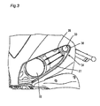
- a headlight unit 30 is disposed on the rear face side of the front cover 10.
- the headlight unit 30 comprises a pair of left and right light components 31 at its front part. Each of the light components 31 is disposed in one of the openings 23.
- the light component 31 comprises a headlight 32, a position light 33, and a light emitting member 34.
- the headlight 32 is disposed toward the center of the saddle-riding type vehicle 1 in front view, while the position light 33 is disposed more to the side of the saddle-riding type vehicle 1.
- the position light 33 is disposed away from the headlight 32, and is disposed diagonally upward with respect to the headlight 32.
- a through-hole 35 is formed between the headlight 32 and the position light 33. When the vehicle is being ridden, the through-holes 35 introduce outside air and supply it to the engine 9.
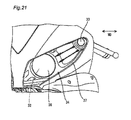
- FIG. 4 is a front view of the light emitting member 34.
- the light emitting member 34 comprises a light cover 36 and a light guide 37.
- the light cover 36 is disposed in front of the position light 33, and covers the position light 33.
- the light emitted from the position light 33 is transmitted forward through the light cover 36.
- the light cover 36 also transmits emitted light from the position light 33 and guides it to an end 37E of the light guide 37 (see FIG. 4 ).
- the light guide 37 is disposed below the position light 33, and extends in the width direction WD of the saddle-riding type vehicle 1. More specifically, the light guide 37 extends diagonally downward from the light cover 36 toward the center of the saddle-riding type vehicle 1.
- FIG. 5 is an oblique view of the light emitting member 34
- FIG. 6 is a plan view of the light guide 37 in the light emitting member 34.
- the light guide 37 has a flat form. That is, the light guide 37 is longer in the width direction WD and shorter in the chassis front and back direction and up and down direction. Accordingly, installing the light guide 37 does not increase the size of the front cover in the up and down direction or the front and back direction.
- the light guide 37 receives emitted light from the position light 33 (light source), and emits light. As shown in FIG. 6 , a plurality of attachment members 371 are formed along the rear edge of the light guide 37. The attachment members 371 are used to attach the light guide 37 to the main part of the headlight unit 30.
- the light guide 37 has emission faces 37F and 37U, and a structured face 37B.
- width direction light R0 the light R0 moving in the width direction of the saddle-riding type vehicle 1
- the light guide 37 fully reflects the width direction light R0 at the structured face 37B and emits upward from the emission face 37U.
- the light guide 37 also fully reflects the width direction light R0 at the structured face 37B and emits forward from the emission face 37F.
- the light guide 37 emits the width direction light R0 in two directions (upward and forward). Since light from the light source can be emitted in two directions by a single member (the light guide 37), the size of the front cover 10 can be kept small, while the emission surface area can be increased.
- the structure of the light guide 37 will be discussed in detail below.
- FIG. 10 is a schematic view of the path taken by the width direction light R0 moving through the light guide 37, and is a schematic of the light guide 37 in plan view.
- the optical structures 370 are indicated by lines in FIG. 10 for the sake of illustration.
- the width direction light R0 emitted from the light source passes through the light cover 36 and is incident on the end 37E of the light guide 37.
- the width direction light R0 moves in the width direction WD through the light guide 37.
- the optical structures 370 are inclined with respect to the width direction WD. Therefore, when the width direction light R0 is incident on the optical structures 370 (on their side faces S2), the width direction light R0 is fully reflected. As shown in FIG.
- the optical structures 370 are inclined with respect to the width direction WD so that of the ends 370F and 370R of the optical structures 370, the ends 370F on the emission face 37F side are disposed farther away from the light source (the position light 33) than the other ends 370R. Accordingly, the light R0 fully reflected by the optical structures 370 moves in the emission face 37F direction. As a result, the width direction light R0 is emitted forward from the light guide 37.
- the light guide 37 also emits the width direction light R0 from the emission face 37U. That is, the light guide 37 emits the width direction light R0 not only forward, but also upward.
- FIG. 11 is a schematic view of the path of the width direction light R0 moving through the light guide 37, when the light guide 37 is seen in front view.
- the optical structures 370 are in the form of grooves, and the width of their lateral cross sectional shape gradually narrows toward the groove bottom.
- the side faces S1 and S2 of the optical structures 370 are flat, and the side faces S2 are disposed closer to the light source (the position light 33) than the side faces S1.
- the width direction light R0 moves through the light guide 37 in the width direction WD.
- the width direction light R0 is incident on and fully reflected by the side faces S2 of the optical structures 370.
- the light R0 fully reflected by the side faces S2 moves upward and is emitted to the outside from the emission face 37U.
- Parts (R01 and R02) of the width direction light R0 moving through the light guide 37 are incident on the emission face 37U.
- the incident angle of the light R01 and R02 on the emission face 37U exceeds the critical angle. Therefore, the light R01 and R02 is fully reflected by the emission face 37U and continues moving through the light guide 37 in the width direction WD.
- the light R01 and R02 is incident on the side faces S2 of the optical structures 370. At this point the light R01 and R02 is fully reflected by the side faces S2 and is emitted upward from the emission face 37U.
- the side faces S2 are preferably disposed inclined so that the incident angle at which the width direction light R0 is incident on the optical structures 370 will be at least the critical angle in a lateral cross section of the optical structures 370. In this case, most of the width direction light R0 is fully reflected and emitted upward from the emission face 37U. This increases the brightness of the emission face 37U.
- the light guide 37 can still emit the light from the light source (the position light 33) upward to a certain extent.
- the light from the light source is light other than the width direction light R0, and includes light that deviates somewhat from the width direction WD. This is because this light is also incident o the light guide 37, moves through the light guide 37 while being fully reflected, and is fully reflected by the side faces S2 and emitted upward.
- the optical structures 370 are inclined with respect to the width direction WD, and of the two ends of the optical structures 370, the end 370F on the emission face 37F is disposed farther away from the light source (the position light 33) than the end 370R on the opposite side.
- the width direction light R0 moving in the light guide 37 is fully reflected by the optical structures 370 and emitted forward from the emission face 37F.
- the optical structures 370 further have a lateral cross sectional shape that gradually narrows toward the groove bottom, and have the side faces S1 and S2.
- the optical structures 370 fully reflect the width direction light R0 at the side faces S2, and emit the light R0 upward from the emission face 37U.
- the light guide 37 can emit the width direction light R0 incident from the light source (the position light 33) in two directions (upward and forward). Therefore, the emission surface area of the saddle-riding type vehicle 1 is expanded by the use of a single member (the light guide 37). Furthermore, as shown in FIGS. 4 and 6 , the length of the light guide 37 in the front and back direction FBD and its length in the direction of a normal line N37U of the emission face 37U are shorter than the length of the light guide 37 in the width direction WD. Therefore, the saddle-riding type vehicle 1 can produce a sufficient quantity of illumination without an increase in the size of the front cover 10. In particular, the size of the front cover 10 can be reduced in the front and back direction and the up and down direction. Preferably, the length of the light guide 37 in the normal line N37U direction is shorter than the length of the light guide 37 in the front and back direction FBD. The size of the front cover 10 in the up and down direction can be made even smaller in this case.
- the light guide 37 preferably has the following configuration in order to minimize brightness unevenness between the emission faces 37F and 37U.
- FIG. 12 is a cross section of the light guide 37 in region A in FIG. 4 (a cross section in the width direction WD).
- FIG. 13 is a cross section of the light guide 37 in region B in FIG. 4 .
- the plurality of optical structures 370 include a plurality of optical structures 370A and a plurality of optical structures 370B.
- the optical structures 370A are disposed closer to the light source (the position light 33) than the optical structures 370B.
- the height H370A of the optical structures 370A is lower than the height H370B of the optical structures 370B.
- the optical structures 370A were lower in height than the optical structures 370B, nearly all of the width direction light R0 would be fully reflected by the optical structures 370A, making it difficult for the width direction light R0 to reach the optical structures 370B. If this happened, there might be uneven brightness at the emission face 37F. More specifically, the brightness of the emission faces 37F and 37U in region A would be higher than that of the emission faces 37F and 37U in region B.
- the optical structures 370A are lower than the optical structures 370B. Therefore, part of the width direction light R0 passes over the optical structures 370A, moves in the width direction WD through the light guide 37, and reaches the optical structures 370B. As a result, the width direction light R0 is fully reflected not only by the optical structures 370A, but also by the optical structures 370B. Therefore, uneven brightness is less apt to occur.
- FIG. 14 is a cross section of the light guide 37 in region C in FIG. 4 .
- the plurality of optical structures 370 further include a plurality of optical structures 370C in region C.
- the optical structures 370C are disposed farther away from the light source than the optical structures 370B, and are taller than the optical structures 370B.
- the optical structures 370 are formed such that the ones closer to the light source (the position light 33) are lower in height. This reduces uneven brightness at the emission faces 37F and 37U.
- adjacent optical structures 370A and 370B are disposed separated from one another, and the distance 370A between adjacent optical structures 370A (see FIG. 12 ) is greater than the distance 370B between adjacent optical structures 370B (see FIG. 13 ).
- the optical structures 370 are formed such that the closer they are to the light source, the greater is the distance between the adjacent optical structures 370. This reduces uneven brightness at the emission faces 37F and 37U.
- the optical structures 370 may also be the same height, and the distances may be the same between adjacent optical structures 370. Adjacent optical structures 370 may also be in contact with each other.
- the light guide 37 can emit the width direction light R0 in two directions (upward and forward).
- the optical structures 370 are prismatic grooves and have the side faces S1 and S2.
- the surface area of the side faces S2 is preferably larger than that of the side faces S1.
- the ones that have the role of emitting light forward and upward are the side faces S2. If the side faces S2 are larger than the side faces S1, then more light can be emitting forward and upward.
- the position light 33 serves as the light source.
- the position light 33 may be an ordinary light bulb in which a light emitting element has been sealed, or may be an LED (light emitting diode) element. If the position light 33 is utilized as the light source, there is no need to provide an additional light source for light guide 37 use. Therefore, the increase in the size of the front cover 10 that would be occasioned by providing an additional light source can be avoided.
- the position light 33 may be used as the light source for light guide 37 use.
- an additional LED element may be provided under the position light 33, and this LED element used as a light source.
- light is emitted in two directions by a single light guide 37. Therefore, the size of the front cover 10 can be reduced somewhat.
- the headlight 32 may be used as a light source instead of the position light 33.
- the light cover 36 of the light emitting member 34 covers the headlight 32.
- the light guide 37 extends in the width direction WD from the light cover 36 covering the headlight 32, toward the side of the saddle-riding type vehicle 1 (that is, toward the position light 33).
- the optical structures 370 are inclined with respect to the width direction WD so that the ends 370F thereof (the ends on the emission face 37F; see FIG. 10 ) are farther away from the headlight 32 than the other ends 370R. That is, the optical structures 370 are inclined to the opposite side from that when the position light 33 is used as the light source. This allows light from the headlight 32 to be emitted forward and upward.
- the light guide 37 may be disposed above the position light 33 and the headlight 32, with the position light 33 serving as the light source.
- the structured face 37B is disposed on the upper face of the light guide 37
- the emission face 37U is disposed on the lower face of the light guide 37. Accordingly, the light guide 37 emits the width direction light R0 forward and downward.
- the light guide 37 allows the size of the front cover 10 to be kept small, while the emission surface area can be increased and visibility improved.
- the saddle-riding type vehicle pertaining to this embodiment comprises a front cover, a light source, and a light guide.
- the front cover is disposed at the front part of the chassis.
- the light source and the light guide are disposed on the front cover.
- the light guide extends in the width direction of the chassis, and receives light moving from the light source in the width direction of the chassis.
- the light guide has first and second emission faces.
- the first emission face faces up or down from the chassis and emits light.
- the second emission face that faces forward from the chassis and emits light.
- the length of the light guide in the front and back direction of the chassis and the length of the light guide in the normal direction of the first emission face are shorter than the length of the light guide in the width direction of the chassis.
- the light guide emits light forward and either upward or downward.
- the length of the light guide in the front and back direction of the chassis and the length of the light guide in the normal direction of the first emission face are shorter than the length of the light guide in the width direction of the chassis. Therefore, the light guide allows the size of the front cover to be kept small while allowing the emission surface area to be increased and visibility to be improved.
- the size of the front cover in the up and down direction can be made even smaller.
- the light guide further comprises a structured face.
- the structured face is disposed on the opposite side from the first emission face, and has a plurality of optical structures aligned with one another.
- the optical structures are grooves that are inclined with respect to the width direction of the chassis, have a lateral cross sectional shape whose width narrows toward the groove bottom, and of the two ends of the optical structures, the ones disposed on the second emission face side are disposed farther away from the light source than the other ends.
- the plurality of optical structures allow the light moving from the light source in the width direction of the saddle-riding type vehicle to be emitted by the light guide in two directions (the first emission face side and the second emission face side). Therefore, the emission surface area can be increased with a single light guide, and the size of the front cover can be kept small.
- the incident angle of light moving from the light source in the width direction of the chassis with respect to the optical structure is at least a critical angle.
- the brightness is increased on the first emission face side.
- the brightness is increased on the second emission face side.
- the plurality of optical structures include a plurality of first optical structures.
- the second optical structures that are disposed closer to the light source than the first optical structures, and are lower than the first optical structures.
- the structured face is disposed below the first emission face.
- the light source is a position light
- the saddle-riding type vehicle further comprises a headlight that is disposed on the front cover away from the position light.
- the size of the front cover can be kept small, while increasing the emission surface area.
- the light guide pertaining to this embodiment is utilized in the above-mentioned saddle-riding type vehicle.
Landscapes
- Engineering & Computer Science (AREA)
- General Engineering & Computer Science (AREA)
- Mechanical Engineering (AREA)
- Non-Portable Lighting Devices Or Systems Thereof (AREA)
Applications Claiming Priority (1)
| Application Number | Priority Date | Filing Date | Title |
|---|---|---|---|
| JP2011195581A JP2013056603A (ja) | 2011-09-08 | 2011-09-08 | 鞍乗り型車両及びそれに用いられる導光体 |
Publications (3)
| Publication Number | Publication Date |
|---|---|
| EP2568321A2 true EP2568321A2 (fr) | 2013-03-13 |
| EP2568321A3 EP2568321A3 (fr) | 2014-04-16 |
| EP2568321B1 EP2568321B1 (fr) | 2021-08-25 |
Family
ID=46939543
Family Applications (1)
| Application Number | Title | Priority Date | Filing Date |
|---|---|---|---|
| EP12183503.7A Active EP2568321B1 (fr) | 2011-09-08 | 2012-09-07 | Véhicule de type à enfourcher avec guide de lumière utilisé dans celui-ci |
Country Status (3)
| Country | Link |
|---|---|
| US (1) | US8936383B2 (fr) |
| EP (1) | EP2568321B1 (fr) |
| JP (1) | JP2013056603A (fr) |
Cited By (7)
| Publication number | Priority date | Publication date | Assignee | Title |
|---|---|---|---|---|
| USD736451S1 (en) * | 2014-07-31 | 2015-08-11 | GM Global Technology Operations LLC | Vehicle front headlamp lens |
| GB2535758A (en) * | 2015-02-26 | 2016-08-31 | Bentley Motors Ltd | Vehicle light assembly and lighting method |
| EP3073183A1 (fr) * | 2015-03-25 | 2016-09-28 | Automotive Lighting Italia S.p.A. | Dispositif d'éclairage pour véhicules |
| EP2987709A4 (fr) * | 2013-03-28 | 2017-01-04 | Honda Motor Co., Ltd. | Phare pour véhicule motorisé à deux roues |
| EP3150431A1 (fr) * | 2015-09-30 | 2017-04-05 | Honda Motor Co., Ltd. | Véhicule motorisé à deux roues |
| EP3055164A4 (fr) * | 2013-10-10 | 2017-05-17 | Honda Motor Company Limited | Structure de phare à diodes électroluminescentes pour motocycle |
| WO2023275102A1 (fr) * | 2021-06-29 | 2023-01-05 | Valeo Vision | Guide de lumière à structure micro-optique combinée, phare de véhicule et véhicule |
Families Citing this family (15)
| Publication number | Priority date | Publication date | Assignee | Title |
|---|---|---|---|---|
| JP2014198546A (ja) * | 2013-03-29 | 2014-10-23 | 本田技研工業株式会社 | 自動二輪車のヘッドライト装置 |
| JP6104675B2 (ja) | 2013-03-29 | 2017-03-29 | 本田技研工業株式会社 | 自動二輪車のヘッドライト装置 |
| JP6190611B2 (ja) | 2013-03-29 | 2017-08-30 | 本田技研工業株式会社 | 自動二輪車のヘッドライト装置 |
| JP6204081B2 (ja) * | 2013-06-19 | 2017-09-27 | 株式会社小糸製作所 | 車両用灯具 |
| JP6105658B2 (ja) * | 2015-03-11 | 2017-03-29 | 本田技研工業株式会社 | 車両用灯火器 |
| JP2016215757A (ja) * | 2015-05-18 | 2016-12-22 | シマノ(シンガポール)プライベートリミテッド | 自転車用発光装置および自転車用発光システム |
| CN108025780B (zh) * | 2015-09-22 | 2020-02-21 | 本田技研工业株式会社 | 摩托车的位置灯结构 |
| CN107289391B (zh) * | 2016-03-30 | 2020-10-23 | 长城汽车股份有限公司 | 导光条及车辆灯具 |
| US10619817B2 (en) * | 2017-01-24 | 2020-04-14 | Valeo North America, Inc. | Vehicle light assembly having a reflex lens with a locking detent |
| JP6890287B2 (ja) * | 2017-09-25 | 2021-06-18 | パナソニックIpマネジメント株式会社 | 照明器具 |
| JP7205194B2 (ja) * | 2018-11-22 | 2023-01-17 | マツダ株式会社 | 車両用灯具 |
| JP7205193B2 (ja) * | 2018-11-22 | 2023-01-17 | マツダ株式会社 | 車両用灯具 |
| CN113474242B (zh) * | 2019-02-27 | 2023-04-18 | 本田技研工业株式会社 | 跨骑型车辆 |
| US11433758B2 (en) * | 2019-07-26 | 2022-09-06 | Yamaha Hatsudoki Kabushiki Kaisha | Recreational off-highway vehicle with vehicle front structure |
| JP2024065839A (ja) * | 2022-10-31 | 2024-05-15 | 市光工業株式会社 | 車両用灯具 |
Citations (1)
| Publication number | Priority date | Publication date | Assignee | Title |
|---|---|---|---|---|
| JP2007062565A (ja) | 2005-08-31 | 2007-03-15 | Honda Motor Co Ltd | 車両用照明装置 |
Family Cites Families (9)
| Publication number | Priority date | Publication date | Assignee | Title |
|---|---|---|---|---|
| US5432876C1 (en) * | 1992-10-19 | 2002-05-21 | Minnesota Mining & Mfg | Illumination devices and optical fibres for use therein |
| US20050189545A1 (en) * | 2001-04-05 | 2005-09-01 | Bridgestone Corporation | Linear light emitter and method of manufacturing the light emitter |
| WO2003075051A1 (fr) * | 2002-03-05 | 2003-09-12 | Koninklijke Philips Electronics N.V. | Systeme d'eclairage combinant un eclairage homogene diffus et un eclairage local direct |
| JP2005114894A (ja) * | 2003-10-06 | 2005-04-28 | Konica Minolta Business Technologies Inc | 線状照明装置 |
| JP2006236588A (ja) | 2005-02-22 | 2006-09-07 | Koito Mfg Co Ltd | 光照明装置及び車両用灯具 |
| JP5279418B2 (ja) * | 2008-04-03 | 2013-09-04 | ヤマハ発動機株式会社 | 自動二輪車 |
| JP5275776B2 (ja) | 2008-12-17 | 2013-08-28 | 株式会社小糸製作所 | 車両用灯具 |
| JP5534677B2 (ja) | 2009-01-16 | 2014-07-02 | 本田技研工業株式会社 | 自動二輪車のポジションライトおよび灯火装置 |
| US8333493B2 (en) * | 2009-04-03 | 2012-12-18 | North American Lighting, Inc. | Dual-direction light pipe for automotive lighting |
-
2011
- 2011-09-08 JP JP2011195581A patent/JP2013056603A/ja not_active Withdrawn
-
2012
- 2012-09-07 EP EP12183503.7A patent/EP2568321B1/fr active Active
- 2012-09-07 US US13/606,504 patent/US8936383B2/en active Active
Patent Citations (1)
| Publication number | Priority date | Publication date | Assignee | Title |
|---|---|---|---|---|
| JP2007062565A (ja) | 2005-08-31 | 2007-03-15 | Honda Motor Co Ltd | 車両用照明装置 |
Cited By (10)
| Publication number | Priority date | Publication date | Assignee | Title |
|---|---|---|---|---|
| EP2987709A4 (fr) * | 2013-03-28 | 2017-01-04 | Honda Motor Co., Ltd. | Phare pour véhicule motorisé à deux roues |
| US9963182B2 (en) | 2013-03-28 | 2018-05-08 | Honda Motor Co., Ltd. | Headlight for two-wheeled motor vehicle |
| EP3055164A4 (fr) * | 2013-10-10 | 2017-05-17 | Honda Motor Company Limited | Structure de phare à diodes électroluminescentes pour motocycle |
| USD736451S1 (en) * | 2014-07-31 | 2015-08-11 | GM Global Technology Operations LLC | Vehicle front headlamp lens |
| GB2535758A (en) * | 2015-02-26 | 2016-08-31 | Bentley Motors Ltd | Vehicle light assembly and lighting method |
| GB2535758B (en) * | 2015-02-26 | 2018-09-05 | Bentley Motors Ltd | Vehicle light assembly and lighting method |
| US10421388B2 (en) | 2015-02-26 | 2019-09-24 | Bentley Motors Limited | Vehicle light assembly and lighting method |
| EP3073183A1 (fr) * | 2015-03-25 | 2016-09-28 | Automotive Lighting Italia S.p.A. | Dispositif d'éclairage pour véhicules |
| EP3150431A1 (fr) * | 2015-09-30 | 2017-04-05 | Honda Motor Co., Ltd. | Véhicule motorisé à deux roues |
| WO2023275102A1 (fr) * | 2021-06-29 | 2023-01-05 | Valeo Vision | Guide de lumière à structure micro-optique combinée, phare de véhicule et véhicule |
Also Published As
| Publication number | Publication date |
|---|---|
| EP2568321B1 (fr) | 2021-08-25 |
| US20130063966A1 (en) | 2013-03-14 |
| JP2013056603A (ja) | 2013-03-28 |
| EP2568321A3 (fr) | 2014-04-16 |
| US8936383B2 (en) | 2015-01-20 |
Similar Documents
| Publication | Publication Date | Title |
|---|---|---|
| EP2568321B1 (fr) | Véhicule de type à enfourcher avec guide de lumière utilisé dans celui-ci | |
| US7182494B2 (en) | Rear lamp unit for vehicle | |
| US6793384B2 (en) | Tail lamp structure for motorcycle | |
| US7815353B2 (en) | Headlight device and vehicle | |
| EP3760916B1 (fr) | Véhicule à enfourcher et dispositif d'éclairage pour véhicule à enfourcher | |
| US20180264993A1 (en) | Headlight structure of saddled vehicle | |
| US9676437B2 (en) | Headlight structure for vehicle | |
| JP2016005942A (ja) | 鞍乗型車両 | |
| EP3354545B1 (fr) | Module d'éclairage pour phare de véhicule | |
| CN110450892B (zh) | 自动二轮车 | |
| US7322725B2 (en) | Light device for vehicle and vehicle provided with same | |
| CN102089199A (zh) | 骑乘式车辆 | |
| EP3560805B1 (fr) | Véhicule à enfourcher | |
| WO2020174763A1 (fr) | Véhicule à selle | |
| US20130069777A1 (en) | Turn signal structure for saddle ride-type vehicle | |
| CN109973915A (zh) | 鞍座式骑乘车辆的前灯 | |
| WO2022163442A1 (fr) | Véhicule de type à selle | |
| JP2010215054A (ja) | 自動二輪車 | |
| JP6944966B2 (ja) | 灯火器 | |
| US10322763B2 (en) | Head lamp device of straddle-type vehicle | |
| JP2022070603A (ja) | 灯火器構造 | |
| KR20210071436A (ko) | 조명용 광학렌즈 및 이를 이용한 조명장치 | |
| WO2024161955A1 (fr) | Lampe de véhicule | |
| US10627068B2 (en) | Headlight device for saddled vehicle | |
| JP7049299B2 (ja) | ヘッドライト及び鞍乗型車両 |
Legal Events
| Date | Code | Title | Description |
|---|---|---|---|
| PUAI | Public reference made under article 153(3) epc to a published international application that has entered the european phase |
Free format text: ORIGINAL CODE: 0009012 |
|
| AK | Designated contracting states |
Kind code of ref document: A2 Designated state(s): AL AT BE BG CH CY CZ DE DK EE ES FI FR GB GR HR HU IE IS IT LI LT LU LV MC MK MT NL NO PL PT RO RS SE SI SK SM TR |
|
| AX | Request for extension of the european patent |
Extension state: BA ME |
|
| PUAL | Search report despatched |
Free format text: ORIGINAL CODE: 0009013 |
|
| AK | Designated contracting states |
Kind code of ref document: A3 Designated state(s): AL AT BE BG CH CY CZ DE DK EE ES FI FR GB GR HR HU IE IS IT LI LT LU LV MC MK MT NL NO PL PT RO RS SE SI SK SM TR |
|
| AX | Request for extension of the european patent |
Extension state: BA ME |
|
| RIC1 | Information provided on ipc code assigned before grant |
Ipc: B60Q 1/26 20060101ALI20140307BHEP Ipc: F21V 8/00 20060101ALI20140307BHEP Ipc: F21S 8/10 20060101ALI20140307BHEP Ipc: B62J 6/00 20060101ALI20140307BHEP Ipc: B60Q 1/00 20060101ALI20140307BHEP Ipc: G02B 6/00 20060101AFI20140307BHEP |
|
| 17P | Request for examination filed |
Effective date: 20141009 |
|
| RBV | Designated contracting states (corrected) |
Designated state(s): AL AT BE BG CH CY CZ DE DK EE ES FI FR GB GR HR HU IE IS IT LI LT LU LV MC MK MT NL NO PL PT RO RS SE SI SK SM TR |
|
| 17Q | First examination report despatched |
Effective date: 20160520 |
|
| STAA | Information on the status of an ep patent application or granted ep patent |
Free format text: STATUS: EXAMINATION IS IN PROGRESS |
|
| REG | Reference to a national code |
Ref country code: DE Ref legal event code: R079 Ref document number: 602012076505 Country of ref document: DE Free format text: PREVIOUS MAIN CLASS: G02B0006000000 Ipc: F21S0043239000 |
|
| GRAP | Despatch of communication of intention to grant a patent |
Free format text: ORIGINAL CODE: EPIDOSNIGR1 |
|
| STAA | Information on the status of an ep patent application or granted ep patent |
Free format text: STATUS: GRANT OF PATENT IS INTENDED |
|
| RIC1 | Information provided on ipc code assigned before grant |
Ipc: F21S 43/239 20180101AFI20210219BHEP Ipc: F21S 43/245 20180101ALI20210219BHEP |
|
| INTG | Intention to grant announced |
Effective date: 20210318 |
|
| GRAS | Grant fee paid |
Free format text: ORIGINAL CODE: EPIDOSNIGR3 |
|
| GRAA | (expected) grant |
Free format text: ORIGINAL CODE: 0009210 |
|
| STAA | Information on the status of an ep patent application or granted ep patent |
Free format text: STATUS: THE PATENT HAS BEEN GRANTED |
|
| AK | Designated contracting states |
Kind code of ref document: B1 Designated state(s): AL AT BE BG CH CY CZ DE DK EE ES FI FR GB GR HR HU IE IS IT LI LT LU LV MC MK MT NL NO PL PT RO RS SE SI SK SM TR |
|
| REG | Reference to a national code |
Ref country code: GB Ref legal event code: FG4D |
|
| REG | Reference to a national code |
Ref country code: CH Ref legal event code: EP |
|
| REG | Reference to a national code |
Ref country code: DE Ref legal event code: R096 Ref document number: 602012076505 Country of ref document: DE |
|
| REG | Reference to a national code |
Ref country code: IE Ref legal event code: FG4D Ref country code: AT Ref legal event code: REF Ref document number: 1424159 Country of ref document: AT Kind code of ref document: T Effective date: 20210915 |
|
| REG | Reference to a national code |
Ref country code: LT Ref legal event code: MG9D |
|
| REG | Reference to a national code |
Ref country code: NL Ref legal event code: MP Effective date: 20210825 |
|
| REG | Reference to a national code |
Ref country code: AT Ref legal event code: MK05 Ref document number: 1424159 Country of ref document: AT Kind code of ref document: T Effective date: 20210825 |
|
| PG25 | Lapsed in a contracting state [announced via postgrant information from national office to epo] |
Ref country code: HR Free format text: LAPSE BECAUSE OF FAILURE TO SUBMIT A TRANSLATION OF THE DESCRIPTION OR TO PAY THE FEE WITHIN THE PRESCRIBED TIME-LIMIT Effective date: 20210825 Ref country code: SE Free format text: LAPSE BECAUSE OF FAILURE TO SUBMIT A TRANSLATION OF THE DESCRIPTION OR TO PAY THE FEE WITHIN THE PRESCRIBED TIME-LIMIT Effective date: 20210825 Ref country code: NO Free format text: LAPSE BECAUSE OF FAILURE TO SUBMIT A TRANSLATION OF THE DESCRIPTION OR TO PAY THE FEE WITHIN THE PRESCRIBED TIME-LIMIT Effective date: 20211125 Ref country code: PT Free format text: LAPSE BECAUSE OF FAILURE TO SUBMIT A TRANSLATION OF THE DESCRIPTION OR TO PAY THE FEE WITHIN THE PRESCRIBED TIME-LIMIT Effective date: 20211227 Ref country code: RS Free format text: LAPSE BECAUSE OF FAILURE TO SUBMIT A TRANSLATION OF THE DESCRIPTION OR TO PAY THE FEE WITHIN THE PRESCRIBED TIME-LIMIT Effective date: 20210825 Ref country code: FI Free format text: LAPSE BECAUSE OF FAILURE TO SUBMIT A TRANSLATION OF THE DESCRIPTION OR TO PAY THE FEE WITHIN THE PRESCRIBED TIME-LIMIT Effective date: 20210825 Ref country code: ES Free format text: LAPSE BECAUSE OF FAILURE TO SUBMIT A TRANSLATION OF THE DESCRIPTION OR TO PAY THE FEE WITHIN THE PRESCRIBED TIME-LIMIT Effective date: 20210825 Ref country code: LT Free format text: LAPSE BECAUSE OF FAILURE TO SUBMIT A TRANSLATION OF THE DESCRIPTION OR TO PAY THE FEE WITHIN THE PRESCRIBED TIME-LIMIT Effective date: 20210825 Ref country code: BG Free format text: LAPSE BECAUSE OF FAILURE TO SUBMIT A TRANSLATION OF THE DESCRIPTION OR TO PAY THE FEE WITHIN THE PRESCRIBED TIME-LIMIT Effective date: 20211125 Ref country code: AT Free format text: LAPSE BECAUSE OF FAILURE TO SUBMIT A TRANSLATION OF THE DESCRIPTION OR TO PAY THE FEE WITHIN THE PRESCRIBED TIME-LIMIT Effective date: 20210825 |
|
| PG25 | Lapsed in a contracting state [announced via postgrant information from national office to epo] |
Ref country code: PL Free format text: LAPSE BECAUSE OF FAILURE TO SUBMIT A TRANSLATION OF THE DESCRIPTION OR TO PAY THE FEE WITHIN THE PRESCRIBED TIME-LIMIT Effective date: 20210825 Ref country code: LV Free format text: LAPSE BECAUSE OF FAILURE TO SUBMIT A TRANSLATION OF THE DESCRIPTION OR TO PAY THE FEE WITHIN THE PRESCRIBED TIME-LIMIT Effective date: 20210825 Ref country code: GR Free format text: LAPSE BECAUSE OF FAILURE TO SUBMIT A TRANSLATION OF THE DESCRIPTION OR TO PAY THE FEE WITHIN THE PRESCRIBED TIME-LIMIT Effective date: 20211126 |
|
| PG25 | Lapsed in a contracting state [announced via postgrant information from national office to epo] |
Ref country code: NL Free format text: LAPSE BECAUSE OF FAILURE TO SUBMIT A TRANSLATION OF THE DESCRIPTION OR TO PAY THE FEE WITHIN THE PRESCRIBED TIME-LIMIT Effective date: 20210825 |
|
| PG25 | Lapsed in a contracting state [announced via postgrant information from national office to epo] |
Ref country code: DK Free format text: LAPSE BECAUSE OF FAILURE TO SUBMIT A TRANSLATION OF THE DESCRIPTION OR TO PAY THE FEE WITHIN THE PRESCRIBED TIME-LIMIT Effective date: 20210825 |
|
| REG | Reference to a national code |
Ref country code: CH Ref legal event code: PL |
|
| REG | Reference to a national code |
Ref country code: BE Ref legal event code: MM Effective date: 20210930 |
|
| REG | Reference to a national code |
Ref country code: DE Ref legal event code: R097 Ref document number: 602012076505 Country of ref document: DE |
|
| PG25 | Lapsed in a contracting state [announced via postgrant information from national office to epo] |
Ref country code: SM Free format text: LAPSE BECAUSE OF FAILURE TO SUBMIT A TRANSLATION OF THE DESCRIPTION OR TO PAY THE FEE WITHIN THE PRESCRIBED TIME-LIMIT Effective date: 20210825 Ref country code: SK Free format text: LAPSE BECAUSE OF FAILURE TO SUBMIT A TRANSLATION OF THE DESCRIPTION OR TO PAY THE FEE WITHIN THE PRESCRIBED TIME-LIMIT Effective date: 20210825 Ref country code: RO Free format text: LAPSE BECAUSE OF FAILURE TO SUBMIT A TRANSLATION OF THE DESCRIPTION OR TO PAY THE FEE WITHIN THE PRESCRIBED TIME-LIMIT Effective date: 20210825 Ref country code: MC Free format text: LAPSE BECAUSE OF FAILURE TO SUBMIT A TRANSLATION OF THE DESCRIPTION OR TO PAY THE FEE WITHIN THE PRESCRIBED TIME-LIMIT Effective date: 20210825 Ref country code: EE Free format text: LAPSE BECAUSE OF FAILURE TO SUBMIT A TRANSLATION OF THE DESCRIPTION OR TO PAY THE FEE WITHIN THE PRESCRIBED TIME-LIMIT Effective date: 20210825 Ref country code: CZ Free format text: LAPSE BECAUSE OF FAILURE TO SUBMIT A TRANSLATION OF THE DESCRIPTION OR TO PAY THE FEE WITHIN THE PRESCRIBED TIME-LIMIT Effective date: 20210825 Ref country code: AL Free format text: LAPSE BECAUSE OF FAILURE TO SUBMIT A TRANSLATION OF THE DESCRIPTION OR TO PAY THE FEE WITHIN THE PRESCRIBED TIME-LIMIT Effective date: 20210825 |
|
| PLBE | No opposition filed within time limit |
Free format text: ORIGINAL CODE: 0009261 |
|
| STAA | Information on the status of an ep patent application or granted ep patent |
Free format text: STATUS: NO OPPOSITION FILED WITHIN TIME LIMIT |
|
| GBPC | Gb: european patent ceased through non-payment of renewal fee |
Effective date: 20211125 |
|
| PG25 | Lapsed in a contracting state [announced via postgrant information from national office to epo] |
Ref country code: LU Free format text: LAPSE BECAUSE OF NON-PAYMENT OF DUE FEES Effective date: 20210907 Ref country code: IE Free format text: LAPSE BECAUSE OF NON-PAYMENT OF DUE FEES Effective date: 20210907 Ref country code: BE Free format text: LAPSE BECAUSE OF NON-PAYMENT OF DUE FEES Effective date: 20210930 |
|
| 26N | No opposition filed |
Effective date: 20220527 |
|
| PG25 | Lapsed in a contracting state [announced via postgrant information from national office to epo] |
Ref country code: SI Free format text: LAPSE BECAUSE OF FAILURE TO SUBMIT A TRANSLATION OF THE DESCRIPTION OR TO PAY THE FEE WITHIN THE PRESCRIBED TIME-LIMIT Effective date: 20210825 Ref country code: LI Free format text: LAPSE BECAUSE OF NON-PAYMENT OF DUE FEES Effective date: 20210930 Ref country code: CH Free format text: LAPSE BECAUSE OF NON-PAYMENT OF DUE FEES Effective date: 20210930 |
|
| PG25 | Lapsed in a contracting state [announced via postgrant information from national office to epo] |
Ref country code: GB Free format text: LAPSE BECAUSE OF NON-PAYMENT OF DUE FEES Effective date: 20211125 |
|
| PG25 | Lapsed in a contracting state [announced via postgrant information from national office to epo] |
Ref country code: HU Free format text: LAPSE BECAUSE OF FAILURE TO SUBMIT A TRANSLATION OF THE DESCRIPTION OR TO PAY THE FEE WITHIN THE PRESCRIBED TIME-LIMIT; INVALID AB INITIO Effective date: 20120907 Ref country code: CY Free format text: LAPSE BECAUSE OF FAILURE TO SUBMIT A TRANSLATION OF THE DESCRIPTION OR TO PAY THE FEE WITHIN THE PRESCRIBED TIME-LIMIT Effective date: 20210825 |
|
| P01 | Opt-out of the competence of the unified patent court (upc) registered |
Effective date: 20230527 |
|
| PG25 | Lapsed in a contracting state [announced via postgrant information from national office to epo] |
Ref country code: MK Free format text: LAPSE BECAUSE OF FAILURE TO SUBMIT A TRANSLATION OF THE DESCRIPTION OR TO PAY THE FEE WITHIN THE PRESCRIBED TIME-LIMIT Effective date: 20210825 |
|
| PG25 | Lapsed in a contracting state [announced via postgrant information from national office to epo] |
Ref country code: TR Free format text: LAPSE BECAUSE OF FAILURE TO SUBMIT A TRANSLATION OF THE DESCRIPTION OR TO PAY THE FEE WITHIN THE PRESCRIBED TIME-LIMIT Effective date: 20210825 |
|
| PG25 | Lapsed in a contracting state [announced via postgrant information from national office to epo] |
Ref country code: MT Free format text: LAPSE BECAUSE OF FAILURE TO SUBMIT A TRANSLATION OF THE DESCRIPTION OR TO PAY THE FEE WITHIN THE PRESCRIBED TIME-LIMIT Effective date: 20210825 |
|
| PGFP | Annual fee paid to national office [announced via postgrant information from national office to epo] |
Ref country code: DE Payment date: 20250919 Year of fee payment: 14 |
|
| PGFP | Annual fee paid to national office [announced via postgrant information from national office to epo] |
Ref country code: IT Payment date: 20250923 Year of fee payment: 14 |
|
| PGFP | Annual fee paid to national office [announced via postgrant information from national office to epo] |
Ref country code: FR Payment date: 20250922 Year of fee payment: 14 |