EP2568323A1 - Panneau de raccordement optique à haute densité - Google Patents
Panneau de raccordement optique à haute densité Download PDFInfo
- Publication number
- EP2568323A1 EP2568323A1 EP12425148A EP12425148A EP2568323A1 EP 2568323 A1 EP2568323 A1 EP 2568323A1 EP 12425148 A EP12425148 A EP 12425148A EP 12425148 A EP12425148 A EP 12425148A EP 2568323 A1 EP2568323 A1 EP 2568323A1
- Authority
- EP
- European Patent Office
- Prior art keywords
- fibers
- high density
- patch panel
- density optical
- modular component
- Prior art date
- Legal status (The legal status is an assumption and is not a legal conclusion. Google has not performed a legal analysis and makes no representation as to the accuracy of the status listed.)
- Withdrawn
Links
- 230000003287 optical effect Effects 0.000 title claims abstract description 35
- 239000000835 fiber Substances 0.000 claims abstract description 44
- 230000000284 resting effect Effects 0.000 claims description 2
- 238000005516 engineering process Methods 0.000 description 5
- 230000005540 biological transmission Effects 0.000 description 4
- 230000000694 effects Effects 0.000 description 4
- 239000013307 optical fiber Substances 0.000 description 4
- 239000006185 dispersion Substances 0.000 description 3
- RYGMFSIKBFXOCR-UHFFFAOYSA-N Copper Chemical compound [Cu] RYGMFSIKBFXOCR-UHFFFAOYSA-N 0.000 description 2
- 229910052802 copper Inorganic materials 0.000 description 2
- 239000010949 copper Substances 0.000 description 2
- 238000009792 diffusion process Methods 0.000 description 1
- 238000009434 installation Methods 0.000 description 1
- 238000004519 manufacturing process Methods 0.000 description 1
- 230000004048 modification Effects 0.000 description 1
- 238000012986 modification Methods 0.000 description 1
- 230000008520 organization Effects 0.000 description 1
Images


Classifications
-
- G—PHYSICS
- G02—OPTICS
- G02B—OPTICAL ELEMENTS, SYSTEMS OR APPARATUS
- G02B6/00—Light guides; Structural details of arrangements comprising light guides and other optical elements, e.g. couplings
- G02B6/44—Mechanical structures for providing tensile strength and external protection for fibres, e.g. optical transmission cables
- G02B6/4439—Auxiliary devices
- G02B6/444—Systems or boxes with surplus lengths
- G02B6/44528—Patch-cords; Connector arrangements in the system or in the box
-
- G—PHYSICS
- G02—OPTICS
- G02B—OPTICAL ELEMENTS, SYSTEMS OR APPARATUS
- G02B6/00—Light guides; Structural details of arrangements comprising light guides and other optical elements, e.g. couplings
- G02B6/44—Mechanical structures for providing tensile strength and external protection for fibres, e.g. optical transmission cables
- G02B6/4439—Auxiliary devices
- G02B6/444—Systems or boxes with surplus lengths
- G02B6/4452—Distribution frames
- G02B6/44526—Panels or rackmounts covering a whole width of the frame or rack
Definitions
- the present invention relates to a high density optical split patch panel.
- the invention concerns a device of the above kind, specifically realized for all the needs of junction and organization of optical fibers within a telephone exchange.
- Telephone operator companies which already before the onset of these new technologies possessed a dense network of connections between possible users and service providers, consisting of the telephone network, immediately used their network infrastructure to provide the possibility to exchange information and data, and have long tried to use transmission systems increasingly able to send at the same time the amount of information.
- the numerical capacity of information that can be transmitted through the same transmission system depends on the width of the transmission "band". The wider is the band the more the transmission system is capable and efficient.
- the available bandwidth depends on the apparatuses and the physical carrier of the network.
- bandwidths of the order of ten Mbit
- fiber optic network bandwidths can be reached of the order of hundreds of Mbits. It is increasingly stringent, thus, the need to replace the copper network with a fiber optic network.
- optical network is being slowly realized, but it will take some time and a lot of financial commitment by governments and/or telephone operator companies until all users are connected to the optical fiber.
- a user can be connected to the telephone exchange by means of a single fiber, as expected in Italy, or by more fibers, for example four, as expected in France.
- optical Island For these operational requirements, within the telephone exchange it is necessary to build a so-called “optic Island", where all the optical fibers start and finish.
- the purpose of the present invention is therefore to provide a high density optical split patch panel that allows to overcome the limits of the solutions according to the prior art technology and to obtain the technical results previously described.
- optical split patch panel can be manufactured with substantially low costs, both as regards production costs and as regards the costs of management and installation.
- Another object of the invention is to provide a high density optical split patch panel which is substantially simple, safe and reliable.
- a high density optical split patch panel comprising one or more modular components, at the sides of which paths are arranged for the passage of fibers, each modular component being provided with a support plate, on which a frame is housed, to which a front central plate is hinged on one side thereof, on which a plurality of optical connectors of the fibers and a plurality of distributors of the fibers are accommodated, between said support plate and said central plate a space being defined for housing accessories for the joining of the fibers and/or sinks of the fiber.
- At least one channel is present for the passage of fibers from a modular component to an adjacent modular component and/or at least one opening for the passage of fibers from a modular component to a modular component placed at its back.
- said front central plate is hinged to said frame by hinge means which comprise at least one hinge which has a circumferential open conformation.
- said hinge is arranged at the lower part of said front central plate.
- said hinge is composed of two open annular members, resting on each other with possibility of rotation, respectively a first open annular member integral with said frame, and a second open annular members, integral with said plate.
- said first open annular member has a central guide, which runs along its entire circumference and is intended to house, with freedom of movement in rotation, a corresponding protrusion of said second open annular member.
- a high density optical split patch panel generally designated by the reference numeral 1, functional and easily manageable from the point of view of normal use and which forms said optic island.
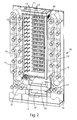
- the basic element of the high density optical split patch panel 1 is the modular component 10, of which Figure 2 shows an overall view.
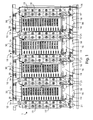
- Figure 1 shows a high density optical split patch panel 1 which comprises four modular components 10 arranged side by side.
- a feature of the modular component 10 is that it has a depth of 30 cm, as all the cabinets of the telephone exchange, so-called “in a row”, so that it can be installed "back to back” constituting a double row in line.
- the in-line arrangement of a single or double row (back to back) allows a better use of available area on the telephone exchange.
- the high density optical split patch panel 1 may then be formed by four modular components 10 which can be modulated and repeated in the line, plus four other in the double row, according to the needs arising from the number of fibers to manage.
- Each modular component 10 is constituted by a rear support plate 11 on which a plurality of elements are arranged, and in particular a front central plate 12, with folded edges, on which there are accommodated a plurality of optical connectors 13 of the fibers and a plurality of elements of fiber management, more properly defined distributors 14 of the fibers.
- vertical paths 15, 15' are arranged for the obliged passage and the dispersion of fibers.
- a first vertical path 15 can be destined to the fibers that come from the telephone exchange apparatus, while a second vertical path 15' may be intended for fibers that come from external optical cables which connect users.
- the base of the modular component 10, under the support plate 11, is constituted by two horizontal channels 16, 17.
- the first channel 16 it is possible to collect the fibers going from a modular component 10 to the next in line on the same side of the high density optical split patch panel 1.
- the second channel 17 is instead possible to collect the fibers that go to the opposite side in straight line of the high density optical split patch panel 1, in the case where the same distribution frame accommodates modular components 10 arranged back to back.
- channels 16 and 17 may be exchanged, and consequently both channels 16, 17 of each modular component 10 are provided with respective openings 18, 19, which serve to allow the passage of fibers from one side to the opposite side of modular components 10 arranged back to back on the same high density optical split patch panel 1.
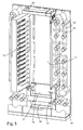
- the front central plate 12 is pivoted on a side, by means of two hinges, to a frame 20 which, while retaining the front central plate 12 to a certain distance from the support plate 11, forms a door which closes an internal area of the modular component 10.
- the front central plate 12 rotates on two hinges.
- a first hinge (not shown), arranged at the upper part of the front central plate 12, is a normal hinge of the axial type, while a second hinge 21 arranged at the bottom of the front central plate 12, is a particularly and specifically made hinge 21, characterized in that it has a circumferential open conformation.
- Such particular conformation of the hinge 21 has the function of allowing the passage to the inside of the fibers that from the front central plate 12 descend downwards, to move towards the various vertical paths 15, 15', ie towards the channels 16, 17. In fact, passing through the passage defined by this hinge 21, the fibers do not undergo stresses upon rotation of the front central plate 12 around the hinge 21.
- the hinge 21 has an opening on the front portion of its circumferential structure, in such a way as to allow that the fibers can be arranged inside without requiring an operation of threading.
- Some pins 22, 22' respectively a first pin 22 integral with the frame 20 and a second pin 22' integral with the plate 12, contributes to stable driving of the fibers inside the hinge 21.
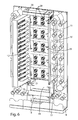
- the open circumferential hinge 21 is composed of two open annular members 23, 24, a first open annular member 23 and a second open annular member 24.
- the first open annular member 23 is integral with the frame 20, while the second open annular member 24 is rigidly coupled to the plate 12.
- the first open annular member 23 has a central guide 25, which runs along the entire circumference of the first open annular element 23 and intended to house, with freedom of movement in rotation, a corresponding protrusion 26 of the second open annular element 24.
- the support plate 11 of the modular component 10 may be located accessories 28 for the junction of the fibers, if the modular component 10 is intended for the arrival of the cables coming from the users, or fiber dispersers 29, if the modular component 11 is intended for the arrival of the fibers coming from the apparatuses of rhe telephone exchange.
- the high density optical split patch panel 1 according to the present invention can be constituted by a single modular component 10.
- one and the same modular component 10 may contain within it both connecting elements 28 and accessories of dispersion 29.
- the fibers of the apparatuses always come from above on a dedicated channel, colored in yellow, represented in Figure 1 and indicated by the reference number 30 and, in order to enter into the modular components 10 follow the first vertical path 15 of each modular component.
Landscapes
- Physics & Mathematics (AREA)
- General Physics & Mathematics (AREA)
- Optics & Photonics (AREA)
- Heat-Exchange Devices With Radiators And Conduit Assemblies (AREA)
- Physical Or Chemical Processes And Apparatus (AREA)
- Light Guides In General And Applications Therefor (AREA)
Applications Claiming Priority (1)
| Application Number | Priority Date | Filing Date | Title |
|---|---|---|---|
| IT000473A ITRM20110473A1 (it) | 2011-09-09 | 2011-09-09 | Permutatore ottico ad alta densità. |
Publications (1)
| Publication Number | Publication Date |
|---|---|
| EP2568323A1 true EP2568323A1 (fr) | 2013-03-13 |
Family
ID=44899091
Family Applications (1)
| Application Number | Title | Priority Date | Filing Date |
|---|---|---|---|
| EP12425148A Withdrawn EP2568323A1 (fr) | 2011-09-09 | 2012-09-07 | Panneau de raccordement optique à haute densité |
Country Status (2)
| Country | Link |
|---|---|
| EP (1) | EP2568323A1 (fr) |
| IT (1) | ITRM20110473A1 (fr) |
Cited By (2)
| Publication number | Priority date | Publication date | Assignee | Title |
|---|---|---|---|---|
| EP2960697A1 (fr) * | 2014-06-26 | 2015-12-30 | CCS Technology, Inc. | Dispositif de stockage de l'excédent de câble et système de distribution de fibre optique |
| CN114236723A (zh) * | 2021-12-21 | 2022-03-25 | 宁波盈科光通信科技有限公司 | 高密集光纤配线架 |
Citations (5)
| Publication number | Priority date | Publication date | Assignee | Title |
|---|---|---|---|---|
| US5402515A (en) * | 1994-03-01 | 1995-03-28 | Minnesota Mining And Manufacturing Company | Fiber distribution frame system, cabinets, trays and fiber optic connector couplings |
| WO2001031380A1 (fr) * | 1999-10-27 | 2001-05-03 | Tyco Electronics Raychem Nv | Systeme de branchement de fibres optiques |
| EP1621908A1 (fr) * | 2004-07-27 | 2006-02-01 | Sirti S.p.A. | Boitier de distribution de câbles optiques |
| EP2159617A2 (fr) * | 2008-09-02 | 2010-03-03 | Corning Cable Systems LLC | Ensembles de panneau de connexion haute densité pour télécommunication à fibre optique |
| US7889961B2 (en) * | 2008-03-27 | 2011-02-15 | Corning Cable Systems Llc | Compact, high-density adapter module, housing assembly and frame assembly for optical fiber telecommunications |
-
2011
- 2011-09-09 IT IT000473A patent/ITRM20110473A1/it unknown
-
2012
- 2012-09-07 EP EP12425148A patent/EP2568323A1/fr not_active Withdrawn
Patent Citations (5)
| Publication number | Priority date | Publication date | Assignee | Title |
|---|---|---|---|---|
| US5402515A (en) * | 1994-03-01 | 1995-03-28 | Minnesota Mining And Manufacturing Company | Fiber distribution frame system, cabinets, trays and fiber optic connector couplings |
| WO2001031380A1 (fr) * | 1999-10-27 | 2001-05-03 | Tyco Electronics Raychem Nv | Systeme de branchement de fibres optiques |
| EP1621908A1 (fr) * | 2004-07-27 | 2006-02-01 | Sirti S.p.A. | Boitier de distribution de câbles optiques |
| US7889961B2 (en) * | 2008-03-27 | 2011-02-15 | Corning Cable Systems Llc | Compact, high-density adapter module, housing assembly and frame assembly for optical fiber telecommunications |
| EP2159617A2 (fr) * | 2008-09-02 | 2010-03-03 | Corning Cable Systems LLC | Ensembles de panneau de connexion haute densité pour télécommunication à fibre optique |
Cited By (2)
| Publication number | Priority date | Publication date | Assignee | Title |
|---|---|---|---|---|
| EP2960697A1 (fr) * | 2014-06-26 | 2015-12-30 | CCS Technology, Inc. | Dispositif de stockage de l'excédent de câble et système de distribution de fibre optique |
| CN114236723A (zh) * | 2021-12-21 | 2022-03-25 | 宁波盈科光通信科技有限公司 | 高密集光纤配线架 |
Also Published As
| Publication number | Publication date |
|---|---|
| ITRM20110473A1 (it) | 2013-03-10 |
Similar Documents
| Publication | Publication Date | Title |
|---|---|---|
| US10295771B2 (en) | Telecommunications terminal with removable modules | |
| US7406242B1 (en) | Interconnect enclosures for optical fibers including cross-connect modules and methods for using the same | |
| US10401586B2 (en) | Telecommunications modules having multiple body sections and forward facing input and output adapters | |
| US9134497B2 (en) | Fiber optic cable management module and panel | |
| CN101821655B (zh) | 用于将外部通信网络连接到建筑物的用户网络的模块化系统和方法 | |
| EP2671111B1 (fr) | Répartiteurs de distribution de fibres | |
| RU2670183C2 (ru) | Распределительное устройство с возможностью добавления разветвителей | |
| DE602004006983T2 (de) | Lokalkonvergenzgehäuse für faseroptische kabelnetze | |
| US6631237B2 (en) | Termination and splice panel | |
| EP3126889B1 (fr) | Module répartiteur et enceinte destinée à être utilisée dans celui-ci | |
| US20160062058A1 (en) | Fiber optic solutions for migration between duplex and parallel multi-fiber solutions allowing for full fiber utilization | |
| EP2585867B1 (fr) | Système de distribution de fibres optiques semi-automatisé | |
| US20150230007A1 (en) | Optical interconnection assembly for spine-and-leaf network scale out | |
| EP3317707B1 (fr) | Boîtier de répartition optique et ensemble | |
| US20090238530A1 (en) | Universal fiber distribution hub | |
| EP2989495A1 (fr) | Module d'utilisateur et procédé de connexion d'un réseau de communication externe | |
| WO2013120270A1 (fr) | Boîte d'unité haute densité | |
| US9059814B2 (en) | Modular optical patch panel | |
| EP3324230A1 (fr) | Cadre pour lignes de télécommunication | |
| ITRM20110473A1 (it) | Permutatore ottico ad alta densità. | |
| EP2490057B1 (fr) | Support pour organiseurs de fibres optiques avec un coupleur à fibre optique | |
| NL2004168C2 (nl) | Inrichting voor gebruik op de locatie van een klant van een breedbandnetwerk en breedbandnetwerk systeem gebruikmakend van een dergelijke inrichting. | |
| EP4530692A1 (fr) | Terminal monte sur un brin pour reseau a fibres optiques et procede de fabrication de ce dernier | |
| EP2639614A1 (fr) | Unité de fiche à fibres optiques et dispositif de distribution de fibres optiques | |
| KR20160003585U (ko) | 광섬유 케이블 분배함 및 광케이블 카드 |
Legal Events
| Date | Code | Title | Description |
|---|---|---|---|
| PUAI | Public reference made under article 153(3) epc to a published international application that has entered the european phase |
Free format text: ORIGINAL CODE: 0009012 |
|
| AK | Designated contracting states |
Kind code of ref document: A1 Designated state(s): AL AT BE BG CH CY CZ DE DK EE ES FI FR GB GR HR HU IE IS IT LI LT LU LV MC MK MT NL NO PL PT RO RS SE SI SK SM TR |
|
| AX | Request for extension of the european patent |
Extension state: BA ME |
|
| STAA | Information on the status of an ep patent application or granted ep patent |
Free format text: STATUS: THE APPLICATION IS DEEMED TO BE WITHDRAWN |
|
| 18D | Application deemed to be withdrawn |
Effective date: 20130914 |