EP2568491A1 - Dispositif étanche à l'eau et procédé d'étanchéité - Google Patents
Dispositif étanche à l'eau et procédé d'étanchéité Download PDFInfo
- Publication number
- EP2568491A1 EP2568491A1 EP12183465A EP12183465A EP2568491A1 EP 2568491 A1 EP2568491 A1 EP 2568491A1 EP 12183465 A EP12183465 A EP 12183465A EP 12183465 A EP12183465 A EP 12183465A EP 2568491 A1 EP2568491 A1 EP 2568491A1
- Authority
- EP
- European Patent Office
- Prior art keywords
- button
- elastic body
- terminal
- rod
- case
- Prior art date
- Legal status (The legal status is an assumption and is not a legal conclusion. Google has not performed a legal analysis and makes no representation as to the accuracy of the status listed.)
- Withdrawn
Links
Images


Classifications
-
- H—ELECTRICITY
- H01—ELECTRIC ELEMENTS
- H01H—ELECTRIC SWITCHES; RELAYS; SELECTORS; EMERGENCY PROTECTIVE DEVICES
- H01H13/00—Switches having rectilinearly-movable operating part or parts adapted for pushing or pulling in one direction only, e.g. push-button switch
- H01H13/02—Details
- H01H13/04—Cases; Covers
- H01H13/06—Dustproof, splashproof, drip-proof, waterproof or flameproof casings
- H01H13/063—Casings hermetically closed by a diaphragm through which passes an actuating member
-
- H—ELECTRICITY
- H01—ELECTRIC ELEMENTS
- H01H—ELECTRIC SWITCHES; RELAYS; SELECTORS; EMERGENCY PROTECTIVE DEVICES
- H01H13/00—Switches having rectilinearly-movable operating part or parts adapted for pushing or pulling in one direction only, e.g. push-button switch
- H01H13/02—Details
- H01H13/04—Cases; Covers
- H01H13/06—Dustproof, splashproof, drip-proof, waterproof or flameproof casings
-
- G—PHYSICS
- G04—HOROLOGY
- G04B—MECHANICALLY-DRIVEN CLOCKS OR WATCHES; MECHANICAL PARTS OF CLOCKS OR WATCHES IN GENERAL; TIME PIECES USING THE POSITION OF THE SUN, MOON OR STARS
- G04B37/00—Cases
- G04B37/08—Hermetic sealing of openings, joints, passages or slits
- G04B37/10—Hermetic sealing of openings, joints, passages or slits of winding stems
- G04B37/106—Hermetic sealing of openings, joints, passages or slits of winding stems of push buttons
-
- H—ELECTRICITY
- H01—ELECTRIC ELEMENTS
- H01H—ELECTRIC SWITCHES; RELAYS; SELECTORS; EMERGENCY PROTECTIVE DEVICES
- H01H13/00—Switches having rectilinearly-movable operating part or parts adapted for pushing or pulling in one direction only, e.g. push-button switch
- H01H13/02—Details
- H01H13/12—Movable parts; Contacts mounted thereon
- H01H13/14—Operating parts, e.g. push-button
-
- H—ELECTRICITY
- H04—ELECTRIC COMMUNICATION TECHNIQUE
- H04B—TRANSMISSION
- H04B1/00—Details of transmission systems, not covered by a single one of groups H04B3/00 - H04B13/00; Details of transmission systems not characterised by the medium used for transmission
- H04B1/38—Transceivers, i.e. devices in which transmitter and receiver form a structural unit and in which at least one part is used for functions of transmitting and receiving
Definitions
- the present disclosure relates to a water-proof apparatus and method for water-proofing.
- a water-proofing structure may be introduced to reduce the risk of malfunction of circuits inside the electronic apparatus due to water that may seep into a gap of a device, such as a gap located near or caused by the button area.
- water-proofing may refer to water resistance, or improving a device or structures resistance to damage caused by incidental water contact, or water-proofing according to an industry or commercial standard.
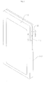
- FIG. 1 is a perspective view illustrating a water-proof structure of a push button according to the prior art.
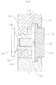
- FIG. 2 is a cross-sectional view illustrating a water-proof structure of a push button according to the prior art.
- a mobile terminal 1 includes a push button 70 on the side of the mobile terminal.
- This structure may be designed to be water-proof.
- the water-proof structure includes a cup member 61, a silicon rubber elastic body, and a packing member 60, a metallic cylindrical holder 62 holding the cup member 61, where a protrusion 71 of a lower portion of a push button 70 is inserted into an opening 60c of the cup member 61.
- the push button 70 and the protrusion 71 may be integral with each other, and the cup member 61, which may provide water-proofing, is installed between the protrusion and a dome switch 39, allowing for a click action.
- a protrusion 61b of the cup member 61 is brought into press-contact with a penetration hole 52, thereby providing water-proofing performance.
- a support force pushing the packing member 60 toward the inner case 32 is needed. If the push button 70 and the protrusion 71 are firmly interposed in the cup member 61 so as to generate a support force, a repelling force is generated against the lateral movement of the push button 70, so that the click sensation is degraded noticeably. Therefore, a hollow cylindrical metal substance is insert-molded on the top portion of the cup member 61 so that the cylindrical holder 62 is coupled thereto, and thus, the click sensation of the push button 70 may be maintained while the support force is generated.
- a technique may be employed to prevent leakage at the molding coupling face between two different materials.
- the introduction of this technique may increase manufacturing costs.
- a flange may be installed at only one side surface of the push button 70 so as to prevent the gap of the push button 70 from being seen from the outside of a portable terminal and prevent the push button 70 from protruding outward from the case. Accordingly, since the position for the placement or assembly of the push button 70 in the case is restricted, there is a disadvantage in that the design may be limited due to the location of the push button 70.
- Exemplary embodiments of the present invention provide a water-proof apparatus and a method for water-proofing, and more specifically a structure with a first button that activates a rod that applies pressure to an elastic body.
- An exemplary embodiment of the present invention discloses a terminal, including: a first button exposed on an exterior of the terminal; an elastic body comprising a coupling hole, the elastic body arranged in a case of the terminal; a rod fitted in the coupling hole, and the rod to be engaged by pressure asserted on the first button, wherein if force is asserted on the first button, the elastic body activates a push switch of the terminal.
- An exemplary embodiment of the present invention discloses an elastic body inserted in a case of a terminal, including: a coupling hole disposed in the elastic body; a rod fitted in the coupling hole, and the rod to be engaged by pressure asserted on a first button, wherein if force is asserted on the first button, the elastic body activates a push switch of the terminal.
- An exemplary embodiment of the present invention discloses a method for providing water-proofing for a terminal, comprising: providing a first button exposed on an exterior of the terminal; providing a non-metal insert comprising a coupling hole, the non-metal insert being fitted in a case of the terminal; and fitting a rod in the coupling hole, the rod being engaged by pressure asserted on the first button, wherein if force is asserted on the first button, the non-metal insert activates a push switch of the terminal.
- FIG. 1 is a perspective view illustrating a water-proof structure of a push button according to the prior art.
- FIG. 2 is a cross-sectional view illustrating a water-proof structure of a push button according to the prior art.
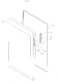
- FIG. 3 is a perspective view illustrating a water-proof structure according to an exemplary embodiment of the present invention.
- FIG. 4 is a cross-sectional view illustrating the water-proof structure according to an exemplary embodiment of the present invention.
- FIG. 5 is an enlarged perspective view illustrating a push key according to an exemplary embodiment of the present invention.
- FIG. 6 is a diagram illustrating a method for assembling the water-proof structure according to an exemplary embodiment of the present invention.
- X, Y, and Z can be construed as X only, Y only, Z only, or any combination of two or more items X, Y, and Z (e.g., XYZ, XYY, YZ, ZZ).
- FIG. 3 is a perspective view illustrating a water-proof structure according to an exemplary embodiment of the present invention.
- FIG. 4 is a cross-sectional view illustrating the water-proof structure according to an exemplary embodiment of the present invention.
- the water-proof structure of the disclosure includes a push key 110, a first case 120, an elastic body 130, a rod 140, and a second case 150.
- the push key 110 may be pushed if a user inputs a signal, and if the push key 110 is pressed toward the inside of the first case 120, a force is transmitted to a push switch 210 through the rod 140 and the elastic body 130, hereby causing a signal to be detected.
- the first case 120 has the push switch 210 disposed therein and includes a penetration hole 122 which is provided in the direction where a pressure is applied to the push switch 210, such as by an application of force, and a groove 124 which accommodates the push key 110.
- the elastic body 130 is inserted into the penetration hole 122 of the first case 120, and includes a coupling hole 132 which is recessed inward. Since the elastic body 130 is inserted into the first case 120, various electronic components including the push switch 210 disposed inside the first case 120 may be protected from water. Unlike the related art, since a metal substance is not insert-molded on the top face of the elastic body 130, the manufacturing process may avoid the usage of metal substances and a body associated with the metal substance, and manufacturing costs may be reduced.
- a protrusion 134 may be disposed on the outer peripheral surface of the elastic body 130, and a coupling groove 126, to which the protrusion 134 of the elastic body 130 is fitted, may be disposed at the intermediate area of the penetration hole 122.
- the elastic body 130 since the elastic body 130 may be coupled to the first case 120, water-proofing may be achieved.
- the bottom face of the elastic body 130 may be provided with a protrusion that faces the push switch 210.
- the rod 140 is fitted to the coupling hole 132 of the elastic body 130, and transmits the pressure applied by the contact of the push key 110 to the push switch 210. Since the rod 140 is positioned and held while being fitted to the elastic body 130, and the rod 140 and the push key 110 are separated from each other, the rod 140 is not affected by the movement of the push key 110 unless a force is applied from the push key 110 toward the push switch 210.
- the push key and the rod may be formed of different materials.
- the push key may be formed of a plastic material
- the rod may be formed of a polymer material.
- the rod 140 may be, for example, a material with a lubricating element. In this case, it is possible to improve the click sensation if the user inputs a signal through the push key 110. Further, if the rod 140 is a material with a lubricating element, a compression amount may be increased by narrowing a gap between the rod 140 and the coupling hole 132 without degrading the click sensation of the user, which may aid in water-proofing.
- FIG. 5 is an enlarged perspective view illustrating a push key according to an exemplary embodiment of the present invention.
- the push key 110 includes push key 110a and push key 110b which are connected to each other so as to be integrated through a connection member 160.
- the push key 110 includes push key 110a and push key 110b which are connected to each other so as to be integrated through a connection member 160.
- two push keys 110 are shown, however, two or more push keys may be provided.
- connection member 160 includes a first flange 162 which extends toward the first case 120 and a second flange 164 which extends toward the second case 150.
- Two flanges 162 and 164 may block a gap between the push key 110 and the cases 120 and 150 so as to be hidden from the outside thereof, and may prevent the push key 110 from being dislodged from the cases 120 and 150.
- FIG. 6 is a diagram illustrating a method for assembling the water-proof structure according to an exemplary embodiment of the present invention.
- the elastic body 130 to which the rod 140 is fitted is coupled to the penetration hole 122 of the first case 120, and the push keys 110a and 110b are integrally formed with the connection member and may be coupled to the side face of the first case 120. Since the rod 140 and the push keys 110a and 110b are separated from each other, the respective components may be separately assembled.
- a partition portion 128 may be formed in the side end of the first case 120 so as to define the area between the push key 110a and push key 110b.
- the water-proof structure of the disclosure may reduce manufacturing costs and allow for a greater freedom in design.
- the water-proof structure disclosed herein may provide a water-proofing performance with a simple structure without insert-molding a separate metal substance with the elastic body.
- water-proof structure disclosed herein may maintain a click sensation of the push key during operation.
- a terminal includes: a first button exposed on an exterior of the terminal; an elastic body comprising a coupling hole, the elastic body arranged in a case of the terminal; a rod fitted in the coupling hole, and the rod to be engaged by pressure asserted on the first button, wherein if force is asserted on the first button, the elastic body activates a push switch of the terminal.
- a method for providing water-proofing for a terminal includes: providing a first button exposed on an exterior of the terminal; providing a non-metal insert comprising a coupling hole, the non-metal insert being fitted in a case of the terminal; and fitting a rod in the coupling hole, the rod being engaged by pressure asserted on the first button, wherein if force is asserted on the first button, the non-metal insert activates a push switch of the terminal.
Landscapes
- Physics & Mathematics (AREA)
- General Physics & Mathematics (AREA)
- Engineering & Computer Science (AREA)
- Computer Networks & Wireless Communication (AREA)
- Signal Processing (AREA)
- Push-Button Switches (AREA)
- Switch Cases, Indication, And Locking (AREA)
Applications Claiming Priority (1)
| Application Number | Priority Date | Filing Date | Title |
|---|---|---|---|
| KR1020110092110A KR101266704B1 (ko) | 2011-09-09 | 2011-09-09 | 방수 키 구조체 |
Publications (1)
| Publication Number | Publication Date |
|---|---|
| EP2568491A1 true EP2568491A1 (fr) | 2013-03-13 |
Family
ID=46970002
Family Applications (1)
| Application Number | Title | Priority Date | Filing Date |
|---|---|---|---|
| EP12183465A Withdrawn EP2568491A1 (fr) | 2011-09-09 | 2012-09-07 | Dispositif étanche à l'eau et procédé d'étanchéité |
Country Status (4)
| Country | Link |
|---|---|
| US (1) | US20130062173A1 (fr) |
| EP (1) | EP2568491A1 (fr) |
| JP (1) | JP2013062243A (fr) |
| KR (1) | KR101266704B1 (fr) |
Cited By (1)
| Publication number | Priority date | Publication date | Assignee | Title |
|---|---|---|---|---|
| WO2016197754A3 (fr) * | 2016-03-14 | 2017-02-02 | 中兴通讯股份有限公司 | Commutateur à bouton-poussoir étanche à l'eau pour terminal mobile, et terminal mobile |
Families Citing this family (9)
| Publication number | Priority date | Publication date | Assignee | Title |
|---|---|---|---|---|
| JP5973335B2 (ja) | 2012-12-13 | 2016-08-23 | 京セラ株式会社 | 防水構造を有する電子機器 |
| US10156423B2 (en) * | 2015-01-09 | 2018-12-18 | Hogue, Inc. | Firearm handgrip assembly with laser gunsight system |
| US9453702B2 (en) * | 2015-01-09 | 2016-09-27 | Hogue, Inc. | Firearm handgrip assembly with laser gunsight system |
| KR102380904B1 (ko) * | 2015-01-28 | 2022-04-01 | 코웨이 주식회사 | 비데 프레임 및 이를 포함하는 비데 |
| JP6551662B2 (ja) * | 2015-06-12 | 2019-07-31 | セイコーエプソン株式会社 | 押しボタン及び押しボタンを含む電子機器 |
| KR101830964B1 (ko) * | 2016-06-17 | 2018-04-04 | 엘지전자 주식회사 | 이동 단말기 |
| JP2016181525A (ja) * | 2016-07-13 | 2016-10-13 | 京セラ株式会社 | 電子機器 |
| CN108540894B (zh) * | 2018-06-26 | 2020-07-07 | 湖南勋兴电子科技有限公司 | 一种耳机防水结构及骨传导耳机 |
| KR102888835B1 (ko) | 2021-02-22 | 2025-11-21 | 삼성전자주식회사 | 방수 구조 및 이를 포함하는 전자 장치 |
Citations (4)
| Publication number | Priority date | Publication date | Assignee | Title |
|---|---|---|---|---|
| US3973099A (en) * | 1974-11-11 | 1976-08-03 | American Micro-Systems, Inc. | Push button switch for electronic watch |
| US20030174590A1 (en) * | 2002-03-14 | 2003-09-18 | Yasuo Arikawa | Push button structure and an electronic device and timepiece having the same |
| US20070034493A1 (en) * | 2005-06-09 | 2007-02-15 | Casio Hitachi Mobile Communications Co., Ltd. | Waterproof structure of push button switch |
| US20110214976A1 (en) * | 2010-03-04 | 2011-09-08 | Pioneer & Co., Inc. | Waterproof operating device |
Family Cites Families (7)
| Publication number | Priority date | Publication date | Assignee | Title |
|---|---|---|---|---|
| JPS6180540U (fr) * | 1984-11-01 | 1986-05-29 | ||
| IT206270Z2 (it) * | 1985-10-09 | 1987-07-20 | Vimercati Off Mec | Interruttore stagno a pulsante |
| JPH03112024A (ja) * | 1989-09-27 | 1991-05-13 | Fujitsu Ltd | 押釦スイッチ |
| DE19503702B4 (de) * | 1995-02-04 | 2005-10-27 | Nicolay Verwaltungs-Gmbh | Flüssigkeits- und gasdicht gekapselter Schalter, insbesondere für elektrochirurgische Instrumente |
| JP3971079B2 (ja) * | 2000-03-14 | 2007-09-05 | アルプス電気株式会社 | 入力装置ならびに検出装置 |
| JP2005310706A (ja) | 2004-04-26 | 2005-11-04 | Daiwa Kasei Ind Co Ltd | プッシュ式スイッチ |
| KR101020881B1 (ko) | 2008-12-24 | 2011-03-09 | 엘지이노텍 주식회사 | 버튼키의 방수장치 |
-
2011
- 2011-09-09 KR KR1020110092110A patent/KR101266704B1/ko not_active Expired - Fee Related
-
2012
- 2012-09-05 US US13/604,533 patent/US20130062173A1/en not_active Abandoned
- 2012-09-05 JP JP2012194853A patent/JP2013062243A/ja active Pending
- 2012-09-07 EP EP12183465A patent/EP2568491A1/fr not_active Withdrawn
Patent Citations (4)
| Publication number | Priority date | Publication date | Assignee | Title |
|---|---|---|---|---|
| US3973099A (en) * | 1974-11-11 | 1976-08-03 | American Micro-Systems, Inc. | Push button switch for electronic watch |
| US20030174590A1 (en) * | 2002-03-14 | 2003-09-18 | Yasuo Arikawa | Push button structure and an electronic device and timepiece having the same |
| US20070034493A1 (en) * | 2005-06-09 | 2007-02-15 | Casio Hitachi Mobile Communications Co., Ltd. | Waterproof structure of push button switch |
| US20110214976A1 (en) * | 2010-03-04 | 2011-09-08 | Pioneer & Co., Inc. | Waterproof operating device |
Cited By (2)
| Publication number | Priority date | Publication date | Assignee | Title |
|---|---|---|---|---|
| WO2016197754A3 (fr) * | 2016-03-14 | 2017-02-02 | 中兴通讯股份有限公司 | Commutateur à bouton-poussoir étanche à l'eau pour terminal mobile, et terminal mobile |
| US10341472B2 (en) | 2016-03-14 | 2019-07-02 | Zte Corporation | Waterproof push-button switch for mobile terminal, and mobile terminal |
Also Published As
| Publication number | Publication date |
|---|---|
| KR101266704B1 (ko) | 2013-05-22 |
| KR20130028503A (ko) | 2013-03-19 |
| JP2013062243A (ja) | 2013-04-04 |
| US20130062173A1 (en) | 2013-03-14 |
Similar Documents
| Publication | Publication Date | Title |
|---|---|---|
| EP2568491A1 (fr) | Dispositif étanche à l'eau et procédé d'étanchéité | |
| EP2589060B1 (fr) | Système de commutateur ayant une caractéristique de limitation de déplacement de bouton | |
| US20140085781A1 (en) | Button assembly and electronic device using the same | |
| KR101962838B1 (ko) | 방수 케이스 | |
| KR101883977B1 (ko) | 방수 기능을 구비한 덮개 부재 | |
| US8361643B2 (en) | Battery cover latch mechanism and portable electronic device using same | |
| US20100039299A1 (en) | Key assembly for portable electronic device using the same | |
| JP2013045600A (ja) | 携帯電子機器および防水装置 | |
| US20170194080A1 (en) | Grommet | |
| US11081832B2 (en) | Terminal sealing member, method of producing the same, and connector including the same | |
| CN206806595U (zh) | 一种顶针孔装配组合及电子设备 | |
| CN109148189B (zh) | 腕戴类设备及其按键 | |
| US20220339483A1 (en) | Training device comprising an elastic resistance band | |
| US9784228B2 (en) | Fuel supply apparatus | |
| US9691571B2 (en) | Electronic device with metallic button | |
| WO2006078548A3 (fr) | Contact de plaque de soudure pour dispositifs medicaux implantes | |
| CN110494942A (zh) | 防水开关 | |
| CN109192579B (zh) | 腕戴类设备及其按键 | |
| CN107277210B (zh) | 移动终端及其侧键防水装置 | |
| EP3633704B1 (fr) | Commutateur | |
| KR102476589B1 (ko) | 전자 기기의 초음파 센서 조립체 및 이를 포함하는 전자 기기 | |
| CN211858475U (zh) | 按键安装结构及设备 | |
| US20120023703A1 (en) | Hinge assembly for foldable electronic device | |
| KR102256494B1 (ko) | 단자용 시일 부재, 그 제조법 및 이를 구비하는 커넥터 | |
| JP4287335B2 (ja) | ケーブルブッシュ |
Legal Events
| Date | Code | Title | Description |
|---|---|---|---|
| PUAI | Public reference made under article 153(3) epc to a published international application that has entered the european phase |
Free format text: ORIGINAL CODE: 0009012 |
|
| 17P | Request for examination filed |
Effective date: 20120907 |
|
| AK | Designated contracting states |
Kind code of ref document: A1 Designated state(s): AL AT BE BG CH CY CZ DE DK EE ES FI FR GB GR HR HU IE IS IT LI LT LU LV MC MK MT NL NO PL PT RO RS SE SI SK SM TR |
|
| AX | Request for extension of the european patent |
Extension state: BA ME |
|
| RBV | Designated contracting states (corrected) |
Designated state(s): AL AT BE BG CH CY CZ DE DK EE ES FI FR GB GR HR HU IE IS IT LI LT LU LV MC MK MT NL NO PL PT RO RS SE SI SK SM TR |
|
| STAA | Information on the status of an ep patent application or granted ep patent |
Free format text: STATUS: THE APPLICATION IS DEEMED TO BE WITHDRAWN |
|
| 18D | Application deemed to be withdrawn |
Effective date: 20150401 |