EP2568567A2 - Verwaltungsapparatur für elektrische Speichervorrichtung - Google Patents
Verwaltungsapparatur für elektrische Speichervorrichtung Download PDFInfo
- Publication number
- EP2568567A2 EP2568567A2 EP12183691A EP12183691A EP2568567A2 EP 2568567 A2 EP2568567 A2 EP 2568567A2 EP 12183691 A EP12183691 A EP 12183691A EP 12183691 A EP12183691 A EP 12183691A EP 2568567 A2 EP2568567 A2 EP 2568567A2
- Authority
- EP
- European Patent Office
- Prior art keywords
- electric storage
- discharging
- storage devices
- voltage
- storage device
- Prior art date
- Legal status (The legal status is an assumption and is not a legal conclusion. Google has not performed a legal analysis and makes no representation as to the accuracy of the status listed.)
- Granted
Links
Images



Classifications
-
- B—PERFORMING OPERATIONS; TRANSPORTING
- B60—VEHICLES IN GENERAL
- B60L—PROPULSION OF ELECTRICALLY-PROPELLED VEHICLES; SUPPLYING ELECTRIC POWER FOR AUXILIARY EQUIPMENT OF ELECTRICALLY-PROPELLED VEHICLES; ELECTRODYNAMIC BRAKE SYSTEMS FOR VEHICLES IN GENERAL; MAGNETIC SUSPENSION OR LEVITATION FOR VEHICLES; MONITORING OPERATING VARIABLES OF ELECTRICALLY-PROPELLED VEHICLES; ELECTRIC SAFETY DEVICES FOR ELECTRICALLY-PROPELLED VEHICLES
- B60L58/00—Methods or circuit arrangements for monitoring or controlling batteries or fuel cells, specially adapted for electric vehicles
- B60L58/10—Methods or circuit arrangements for monitoring or controlling batteries or fuel cells, specially adapted for electric vehicles for monitoring or controlling batteries
- B60L58/12—Methods or circuit arrangements for monitoring or controlling batteries or fuel cells, specially adapted for electric vehicles for monitoring or controlling batteries responding to state of charge [SoC]
- B60L58/15—Preventing overcharging
-
- H—ELECTRICITY
- H02—GENERATION; CONVERSION OR DISTRIBUTION OF ELECTRIC POWER
- H02J—ELECTRIC POWER NETWORKS; CIRCUIT ARRANGEMENTS OR SYSTEMS FOR SUPPLYING OR DISTRIBUTING ELECTRIC POWER; SYSTEMS FOR STORING ELECTRIC ENERGY
- H02J7/00—Circuit arrangements for charging or discharging batteries or for supplying loads from batteries
- H02J7/50—Circuit arrangements for charging or discharging batteries or for supplying loads from batteries acting upon multiple batteries simultaneously or sequentially
- H02J7/52—Circuit arrangements for charging or discharging batteries or for supplying loads from batteries acting upon multiple batteries simultaneously or sequentially for charge balancing, e.g. equalisation of charge between batteries
-
- B—PERFORMING OPERATIONS; TRANSPORTING
- B60—VEHICLES IN GENERAL
- B60L—PROPULSION OF ELECTRICALLY-PROPELLED VEHICLES; SUPPLYING ELECTRIC POWER FOR AUXILIARY EQUIPMENT OF ELECTRICALLY-PROPELLED VEHICLES; ELECTRODYNAMIC BRAKE SYSTEMS FOR VEHICLES IN GENERAL; MAGNETIC SUSPENSION OR LEVITATION FOR VEHICLES; MONITORING OPERATING VARIABLES OF ELECTRICALLY-PROPELLED VEHICLES; ELECTRIC SAFETY DEVICES FOR ELECTRICALLY-PROPELLED VEHICLES
- B60L58/00—Methods or circuit arrangements for monitoring or controlling batteries or fuel cells, specially adapted for electric vehicles
- B60L58/10—Methods or circuit arrangements for monitoring or controlling batteries or fuel cells, specially adapted for electric vehicles for monitoring or controlling batteries
- B60L58/18—Methods or circuit arrangements for monitoring or controlling batteries or fuel cells, specially adapted for electric vehicles for monitoring or controlling batteries of two or more battery modules
- B60L58/22—Balancing the charge of battery modules
-
- H—ELECTRICITY
- H01—ELECTRIC ELEMENTS
- H01M—PROCESSES OR MEANS, e.g. BATTERIES, FOR THE DIRECT CONVERSION OF CHEMICAL ENERGY INTO ELECTRICAL ENERGY
- H01M10/00—Secondary cells; Manufacture thereof
- H01M10/42—Methods or arrangements for servicing or maintenance of secondary cells or secondary half-cells
- H01M10/44—Methods for charging or discharging
- H01M10/441—Methods for charging or discharging for several batteries or cells simultaneously or sequentially
-
- H—ELECTRICITY
- H01—ELECTRIC ELEMENTS
- H01M—PROCESSES OR MEANS, e.g. BATTERIES, FOR THE DIRECT CONVERSION OF CHEMICAL ENERGY INTO ELECTRICAL ENERGY
- H01M10/00—Secondary cells; Manufacture thereof
- H01M10/42—Methods or arrangements for servicing or maintenance of secondary cells or secondary half-cells
- H01M10/48—Accumulators combined with arrangements for measuring, testing or indicating the condition of cells, e.g. the level or density of the electrolyte
- H01M10/482—Accumulators combined with arrangements for measuring, testing or indicating the condition of cells, e.g. the level or density of the electrolyte for several batteries or cells simultaneously or sequentially
-
- H—ELECTRICITY
- H02—GENERATION; CONVERSION OR DISTRIBUTION OF ELECTRIC POWER
- H02J—ELECTRIC POWER NETWORKS; CIRCUIT ARRANGEMENTS OR SYSTEMS FOR SUPPLYING OR DISTRIBUTING ELECTRIC POWER; SYSTEMS FOR STORING ELECTRIC ENERGY
- H02J7/00—Circuit arrangements for charging or discharging batteries or for supplying loads from batteries
- H02J7/50—Circuit arrangements for charging or discharging batteries or for supplying loads from batteries acting upon multiple batteries simultaneously or sequentially
- H02J7/52—Circuit arrangements for charging or discharging batteries or for supplying loads from batteries acting upon multiple batteries simultaneously or sequentially for charge balancing, e.g. equalisation of charge between batteries
- H02J7/54—Passive balancing, e.g. using resistors or parallel MOSFETs
-
- H—ELECTRICITY
- H02—GENERATION; CONVERSION OR DISTRIBUTION OF ELECTRIC POWER
- H02J—ELECTRIC POWER NETWORKS; CIRCUIT ARRANGEMENTS OR SYSTEMS FOR SUPPLYING OR DISTRIBUTING ELECTRIC POWER; SYSTEMS FOR STORING ELECTRIC ENERGY
- H02J7/00—Circuit arrangements for charging or discharging batteries or for supplying loads from batteries
- H02J7/865—Battery or charger load switching, e.g. concurrent charging and load supply
-
- B—PERFORMING OPERATIONS; TRANSPORTING
- B60—VEHICLES IN GENERAL
- B60L—PROPULSION OF ELECTRICALLY-PROPELLED VEHICLES; SUPPLYING ELECTRIC POWER FOR AUXILIARY EQUIPMENT OF ELECTRICALLY-PROPELLED VEHICLES; ELECTRODYNAMIC BRAKE SYSTEMS FOR VEHICLES IN GENERAL; MAGNETIC SUSPENSION OR LEVITATION FOR VEHICLES; MONITORING OPERATING VARIABLES OF ELECTRICALLY-PROPELLED VEHICLES; ELECTRIC SAFETY DEVICES FOR ELECTRICALLY-PROPELLED VEHICLES
- B60L2240/00—Control parameters of input or output; Target parameters
- B60L2240/40—Drive Train control parameters
- B60L2240/54—Drive Train control parameters related to batteries
- B60L2240/547—Voltage
-
- B—PERFORMING OPERATIONS; TRANSPORTING
- B60—VEHICLES IN GENERAL
- B60L—PROPULSION OF ELECTRICALLY-PROPELLED VEHICLES; SUPPLYING ELECTRIC POWER FOR AUXILIARY EQUIPMENT OF ELECTRICALLY-PROPELLED VEHICLES; ELECTRODYNAMIC BRAKE SYSTEMS FOR VEHICLES IN GENERAL; MAGNETIC SUSPENSION OR LEVITATION FOR VEHICLES; MONITORING OPERATING VARIABLES OF ELECTRICALLY-PROPELLED VEHICLES; ELECTRIC SAFETY DEVICES FOR ELECTRICALLY-PROPELLED VEHICLES
- B60L2240/00—Control parameters of input or output; Target parameters
- B60L2240/80—Time limits
-
- H—ELECTRICITY
- H01—ELECTRIC ELEMENTS
- H01M—PROCESSES OR MEANS, e.g. BATTERIES, FOR THE DIRECT CONVERSION OF CHEMICAL ENERGY INTO ELECTRICAL ENERGY
- H01M10/00—Secondary cells; Manufacture thereof
- H01M10/42—Methods or arrangements for servicing or maintenance of secondary cells or secondary half-cells
- H01M10/425—Structural combination with electronic components, e.g. electronic circuits integrated to the outside of the casing
- H01M2010/4271—Battery management systems including electronic circuits, e.g. control of current or voltage to keep battery in healthy state, cell balancing
-
- Y—GENERAL TAGGING OF NEW TECHNOLOGICAL DEVELOPMENTS; GENERAL TAGGING OF CROSS-SECTIONAL TECHNOLOGIES SPANNING OVER SEVERAL SECTIONS OF THE IPC; TECHNICAL SUBJECTS COVERED BY FORMER USPC CROSS-REFERENCE ART COLLECTIONS [XRACs] AND DIGESTS
- Y02—TECHNOLOGIES OR APPLICATIONS FOR MITIGATION OR ADAPTATION AGAINST CLIMATE CHANGE
- Y02E—REDUCTION OF GREENHOUSE GAS [GHG] EMISSIONS, RELATED TO ENERGY GENERATION, TRANSMISSION OR DISTRIBUTION
- Y02E60/00—Enabling technologies; Technologies with a potential or indirect contribution to GHG emissions mitigation
- Y02E60/10—Energy storage using batteries
-
- Y—GENERAL TAGGING OF NEW TECHNOLOGICAL DEVELOPMENTS; GENERAL TAGGING OF CROSS-SECTIONAL TECHNOLOGIES SPANNING OVER SEVERAL SECTIONS OF THE IPC; TECHNICAL SUBJECTS COVERED BY FORMER USPC CROSS-REFERENCE ART COLLECTIONS [XRACs] AND DIGESTS
- Y02—TECHNOLOGIES OR APPLICATIONS FOR MITIGATION OR ADAPTATION AGAINST CLIMATE CHANGE
- Y02T—CLIMATE CHANGE MITIGATION TECHNOLOGIES RELATED TO TRANSPORTATION
- Y02T10/00—Road transport of goods or passengers
- Y02T10/60—Other road transportation technologies with climate change mitigation effect
- Y02T10/70—Energy storage systems for electromobility, e.g. batteries
Definitions
- the present invention disclosed in the present specification relates to a technology of equalizing the capacities of a plurality of electric storage devices under charging or discharging.
- Rechargeable electric storage devices have been used.
- the electric storage devices can be repeatedly used by charging and discharging. Therefore, the electric storage devices are eco-friendly in comparison to nan-rechargeable batteries and thus currently used in various fields including electric vehicles.
- a device using a plurality of electric storage devices may encounter a case where capacities of the electric storage devices become unequal due to fluctuations in initial capacity or deterioration rate of them.
- In charging one or some of the electric storage device (s) sometimes reach a full-charge voltage earlier or later than the other electric storage devices. Therefore, not all of the electric storage devices can be charged fully.
- In discharging one or some of the electric storage devices sometimes reach an end-of-discharge voltage and stop being charged earlier or later than the other electric storage devices. Therefore, not all of the electric storage devices can be fully discharged and exhausted. Thus, if the capacities of the electric storage devices are unequal, those capacities cannot fully be utilized.
- an olivine-type lithium-ion iron secondary battery (hereinafter referred to as an olivine-type iron battery) is attracting attention as a secondary battery for use in electric cars.
- the olivine-type iron battery is a kind of lithium-ion batteries and has a positive electrode including olivine-type iron phosphate and a negative electrode including, for example, a graphite-based material. Therefore, the olivine-type iron battery need not use a cobalt-based electrode as its electrode and has an advantage in that it is more inexpensive and safer than a secondary battery that uses a cobalt-based electrode.
- the olivine-type iron battery has a plateau region extending from a point at which a state of charge (SOC) is at a certain level to a point at which the SOC is at another level.
- the plateau region is defined based on the olivine-type ion battery including a material of the negative electrode.
- the SOC indicates a remaining capacity of the secondary battery.
- the negative electrode includes a graphite-based material
- the plateau region may extend from a point at which the SOC is 10% to a point at which the SOC is 90%.
- the plateau region refers to a region where the voltage of a secondary battery stays roughly constant irrespective of changes in the SOC of the secondary battery.
- the olivine-type iron battery has a region (hereinafter referred to as variation region) in which a voltage sharply increases with respect to an increase in the remaining capacity.
- regions in which the SOC is lower than 10% and higher than 90% may be the variation region.
- electric storage devices such as the secondary batteries having a variation region with such relatively high SOC
- charging of the electric storage devices ends before their equalization ends.
- discharging of the electric storage devices would end upon the end of their charging.
- the electric storage devices could not be sufficiently discharged and the capacities of the electric storage devices are less likely to be equalized.
- An electric storage device management apparatus described herein is provided for monitoring an electric storage device assembly charged and discharged by a charger/discharger.
- the electric storage device assembly includes a plurality of electric storage devices connected in series.
- the electric storage device management apparatus includes a voltmeter, a discharging circuit, and a controller.
- the voltmeter is configured to measure voltages of the electric storage devices, respectively.
- the discharging circuit is configured to discharge the electric storage devices individually.
- the controller is configured to: determine whether a voltage of each electric storage device has reached a reference voltage during charging or discharging of the electric storage device assembly; and control the discharging circuit to discharge each electric storage device if the voltage of the electric storage device has reached the reference voltage.
- the electric storage device management apparatus may further include a memory that stores discharging time period data including discharging time periods associated with sequential numbers.
- the controller may be further configured to: determine a sequence of the electric storage devices according to time at which the voltages of the electric storage devices reach the reference voltage; assign sequential numbers to the electric storage devices, respectively, according to the sequence; determine discharging time periods for the respective electric storage devices according to the respective sequential numbers and the respective discharging time periods associated with the sequential numbers; and control the discharging circuit to discharge the electric storage devices for the respective discharging time periods.
- the discharging time periods may be determined for the electric storage devices under charging such that the discharging time period becomes longer as the sequential number becomes higher.
- the discharging time periods may be determined for the electric storage devices under discharging such that the discharging time period becomes longer as the sequential number becomes lower.
- the controller may control the discharging circuit to discharge the electric storage devices for a plurality of times using the discharging time periods stored in the memory during a plurality of times of charging and discharging of the electric storage devices.
- the controller may be further configured to: measure a time period from when a voltage of a first electric storage device of the electric storage devices has reached the reference voltage to when a voltage of a second electric storage device of the electric storage devices has reached the reference voltage; and update the discharging time periods stored in the memory based on the measured time period in a current process of charging and discharging.
- the updated discharging time periods is stored for a next process of charging and discharging.
- the controller may be further configured to: measure a time period from when a voltage of a first electric storage device of the electric storage devices has reached the reference voltage to when a voltage of a second electric storage device of the electric storage devices has reached the reference voltage; determine the discharging time period based on the measured time period; and control the discharging circuit to discharge the electric storage devices for the determined discharging time period.
- the controller may control the discharging circuit to discharge the first electric storage device under charging for the determined discharging time period.
- the controller may control the discharging circuit to discharge the second electric storage device under discharging for the determined discharging time period.
- the electric storage device management apparatus may further include an ammeter configured to measure a current flowing to or from the electric storage devices during charging or discharging, and an equalization discharge current flowing from each electric storage device during discharging.
- the controller may be further configured to: multiply the current by the time period; determine a result of the multiplication as a capacity variation related to the time period; divide the capacity variation by the equalization discharge current; and determine the discharging time period based on a result of the division.
- the controller may be further configured to: measure an elapsed time period from when charging or discharging of the plurality of electric storage devices is started to when the voltages of each of the electric storage devices has reached the reference voltage; and determine the discharging time period based on the measured elapsed time period.
- the controller may be further configured to continue the control of the discharging unit even if charging or discharging of the plurality of electric storage devices is terminated before the control of the discharging circuit is terminated.
- the controller may be further configured to: control the discharging circuit to discharge the electric storage devices when the reference time has elapsed since the voltage of any one of the electric storage devices has reached the reference voltage; and control the discharging circuit to discharge none of the electric storage devices if the voltage of the one of the electric storage devices has reached the reference voltage within the reference time.
- Each of the electric storage devices may be an olivine-type lithium-ion iron secondary battery.
- the controller may be further configured to set the reference voltage to a voltage that corresponds to an SOC of 90% or higher.
- the SOC indicates a remaining capacity in the electric storage devices under charging.
- the controller may be further configured to set the reference voltage to a voltage that corresponds to an SOC of lower than 10%.
- the SOC indicates a remaining capacity in the electric storage devices under discharging.
- a method of equalizing capacities of electric storage devices connected in series includes: individually measuring a voltage of each of the electric storage devices under charging or discharging; determining whether the voltage has reached a reference voltage; and individually discharging the electric storage devices. The discharging is started if the voltage has reached the reference voltage.
- the electric storage devices in the discharging step, may be discharged over the discharging time period set forehand by being correlated with the order in which the voltages of those electric storage devices reach the reference voltage.
- the method may further include a step of measuring a time period from a time when the voltage of any one of the electric storage devices reaches the reference voltage to a time when the voltage of another one of the electric storage devices reaches the reference voltage.
- the electric storage devices are discharged over the discharging time period that corresponds to the time period.
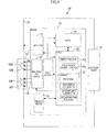
- FIG. 1 is a block diagram of a charging and discharging apparatus
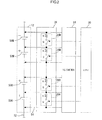
- FIG. 2 is a schematic diagram of a discharging circuit
- FIG. 3 is a flowchart illustrating an equalization process according to a first embodiment
- FIG. 4 is a graph illustrating charging and discharging characteristics of secondary batteries
- FIG. 5 is another graph illustrating the charging and discharging characteristics of the secondary batteries
- FIG. 6 is a flowchart illustrating an equalization process according to a second embodiment
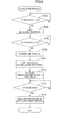
- FIG. 7 is a flowchart illustrating an equalization process according to a third embodiment
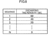
- FIG. 8 is a relational table indicating relationships between sequential numbers and discharging time periods in the third embodiment
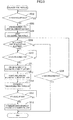
- FIG. 9 is a flowchart illustrating an equalization process according to a fourth embodiment.
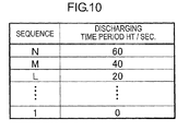
- FIG. 10 is a relational table indicating relationships between sequential numbers and discharging time periods in the fourth embodiment.
- FIGS. 1 to 5 A first embodiment will be described with reference to FIGS. 1 to 5 .
- a charging and discharging system 10 includes a battery assembly 12, a battery management system (BMS) 20, and a charger/load 18.
- the battery assembly 12 includes a plurality of secondary batteries 50 (electric storage devices) connected in series.
- the battery assembly 12 is charged when connected to a charger of the charger/load 18, and discharged when connected to a load of the charger/load 18.
- a remaining capacity of each secondary battery 50 indicates a state of charge (SOC) of the secondary battery 50.
- the BMS 20 controls the remaining capacity (or the SOC) of each secondary battery 50 by monitoring a voltage V and a current I during charging, and equalizes the SOCs of the secondary batteries 50.
- olivine-type lithium-ion iron secondary batteries (hereinafter referred to as olivine-type iron batteries) are used for the secondary batteries 50.
- the secondary batteries 50 are a kind of lithium-ion batteries.
- a positive electrode and a negative electrode of each secondary battery 50 include olivine type iron phosphate and a graphite material, respectively.
- the voltage of the secondary battery 50 sharply rises in a first region in which the SOC is lower than 10% and a second region in which SOC is 90% or higher.
- the first region is in an early stage of charging (or a final stage of discharging) and the second region is in a final stage of charging (or an early stage of discharging).
- the voltage of the secondary battery 50 is substantially constant in a third region in which the SOC is in a range from 10% to 90% (hereinafter referred to as a plateau region).
- the third region is in an intermediate stage of charging or discharging.
- the BMS 20 includes a central processing unit (CPU) 30, an analog-digital converter (ADC) 34, an ammeter 22, a voltmeter 24, a discharging circuit 26, and a thermometer 28.
- CPU central processing unit
- ADC analog-digital converter
- the CPU 30 has a built-in memory (a memory) 32 such as a ROM or RAM.
- a memory 32 such as a ROM or RAM.
- various kinds of programs for controlling operations of the components of the BMS 20 are stored.
- the CPU 30 measures time periods and controls the discharging circuit 26. These functions of the CPU 30 are illustrated in FIG. 1 as functional blocks 42 and 44, respectively.
- the CPU 30 reads the programs from the memory 32 and controls the components in the BMS 20 such as the discharging circuit 26.
- the thermometer 28 is a contact-type or a non-contact-type thermometer provided for measuring a temperature of the battery assembly 12. The measured temperature is stored in the memory 32. As illustrated in FIG. 2 , the voltmeter 24 is connected to both ends of each of the secondary batteries 50 via wirings 54. The voltmeter 24 measures a voltage V of each secondary battery 50 for each predetermined period during charging and discharging.
- the battery assembly 12 includes multiple secondary batteries 50A, 50B, ..., and 50N.
- the voltmeter 24 measures voltages VA, VB, ..., and VN of the respective secondary batteries 50.
- the voltmeter 24 sends the measurements of the voltages V to the ADC 34.
- the discharging circuit 26 is connected to wirings 54 that connect the voltmeter 24 to the secondary batteries 50.
- the discharging circuit 26 discharges the secondary batteries 50 individually.
- the discharging circuit 26 includes individual discharging circuits 26A, 26B, ..., and 26N for discharging the secondary batteries 50, respectively.
- Each individual discharge circuit 26A, 26B, ..., or 26N is connected between the wirings 54.
- Each individual discharge circuit 26A, 26B, .., our 26N includes a resistor R and a switch Q. Closing or opening of the switch Q of the discharging circuit 26 is controlled by the CPU 30. When the switch Q is closed by the CPU 30, a current flows from the secondary battery 50 via the wirings 54 and the resistor R. Therefore, the secondary battery 50 is discharged. When the switch Q is opened, the discharging of the corresponding secondary battery 50 stops.
- the ammeter 22 measures a current flowing through wirings 52 that connect the battery assembly 12 to the charger 18.
- the ammeter 22 also measures a charging/discharging current ZI that flows through all of the secondary batteries 50. Further, the ammeter 22 measures a current HI (or an equalization discharging current) flowing from each secondary battery 50 via the wirings 54. Specifically, the ammeter 22 measures currents IA, IB, ..., and IN flowing from the secondary batteries 50A, 50B, ..., and 50N, respectively.
- the ammeter 22 sends the measurements of the currents I to the ADC 34.
- the ADC 34 is connected to the ammeter 22, the voltmeter 24, and the CPU 30.
- the ADC 34 receives analog data on the currents I and the voltages V from the ammeter 22 and the voltmeter 24, and converts the analog data to digital data.
- the digital data on the currents I and the voltages V is in the memory 32.
- the CPU 30 includes a timer function (the functional block 42). The CPU executes an equalization process, which will be described later, using the data on the currents I and the voltages V stored in the memory 32.
- the equalization process executed by the BMS 20 during charging the battery assembly 12 will be explained with reference to FIGS. 3 to 5 .
- the equalization process is executed associated with a charging control process for controlling the charging of the battery assembly 12.
- the equalization process is executed on the battery assembly 12 by the CPU 30 according to a flowchart illustrated in FIG. 3 .
- the CPU 30 executes the charging control process and the equalization process.
- the CPU 30 first measures the voltage V of each secondary battery 50 and determines whether the voltage V has reached a reference voltage KV. As illustrated in FIG. 4 , a voltage that corresponds to the SOC of 90% or higher is determined as the reference voltage KV and referred to as a reference voltage KV1.
- the CPU 30 starts measuring an elapsed time period from when the voltage V has reached the reference voltage KV1. If a reference time period ST has elapsed since the start of the time measurement, the CPU 30 starts control of the discharging circuit 26 to discharge the secondary battery 50, the voltage V of which has reached the reference voltage KV1. Specifically, the CPU 30 closes the switch Q in the discharging circuit 26 for the first secondary battery 50 and starts measuring a time period since the switch Q is closed. Further, the CPU 30 measures a time period ⁇ T from when the voltage V of the secondary battery 50 has reached the reference voltage KV1 to when the voltage V of another one of the secondary batteries 50 has reached the reference voltage KV1. Another one of the secondary batteries may be the one, a voltage of which rises the slowest.
- the secondary battery 50 the voltage V of which has reached the reference voltage KV the fastest
- the secondary battery 50 the voltage V of which has reached the reference voltage KV the slowest
- the equalization process for the first secondary battery 50 and the second secondary battery 50 will be explained.
- the voltage V of the first secondary battery 50 rises the fastest among the secondary batteries 50, that is, the SOC of the first secondary battery is the highest.
- the voltage V of the second secondary battery 50 rises the slowest among the secondary batteries 50, that is, the SOC of the second secondary battery is the lowest.
- the voltage of the first secondary battery 50 is V1
- the voltage of the second secondary battery 50 is V2
- the time period from when the voltage V1 has reached the reference voltage KV1 to when the voltage V2 has reached the reference voltage KV1 is ⁇ T1.
- the configuration of the first secondary battery 50 described in the following sections may be applied to other secondary batteries other than the second secondary battery50 so that the configurations of all secondary batteries 50 are considered to be described.
- the CPU 30 determines whether the voltage V1 of the first secondary battery 50 has reached the reference voltage KV1 (S2). If the voltage V1 has not reached the reference voltage KV1 (NO in S2), the CPU 30 continues monitoring the voltage V1. If the voltage V1 has reached the reference voltage KV1 (YES in S2), the CPU 30 starts measuring a time period (S4) and discharging of the first secondary battery 50 (S6). The CPU 30 determines whether the voltage V2 of the second secondary battery 50 has reached the reference voltage KV1.
- the CPU 30 monitors the voltage V2 and a total voltage. If the voltage V2 has not reached the reference voltage KV (NO in S6), the CPU 30 determines whether the total voltage of the secondary batteries 50 has reached a charging termination voltage (S8). If the total voltage has not reached the charging termination voltage (NO in S8), the CPU 30 continues monitoring the voltage V2. If the total voltage has reached the charging termination voltage (YES in S8), the CPU 30 sets the discharging time period HT to a predetermined time period KT without measuring the time period ⁇ T1 (S14).
- the CPU 30 measures the time period ⁇ T1 (S10) and determines a discharging time period HT for the first secondary battery 50, the discharge of which has been already started, based on the measured time period ⁇ T1 (S12). Specifically, the CPU 30 integrates charging currents ZI flowing into the battery assembly 12 for the time period ⁇ T1. Namely, the CPU 30 multiplies the charging currents ZI by the time period ⁇ T1 to calculate a capacity difference ⁇ Y1 between the first secondary battery 50 and the second secondary battery 50.
- the memory 32 stores data on the equalization discharging currents HI (or characteristics) of the discharging circuit 26 corresponding to the first secondary battery 50 in advance.
- the CPU 30 determines the discharging time period HT by differentiating (or dividing) the capacity difference ⁇ Y1 by the equalization discharging current HI stored in the memory 32.
- the discharging time period HT may be referred to as an equalization control time period for equalizing the SOCs of the first and second secondary batteries 50.
- the CPU 30 sets the discharge time period HT to a predetermined time period KT without measuring the time period ⁇ T1 (S14).
- the CPU 30 determines whether the discharging time period HT has elapsed since the switch Q is closed (S18). If the discharging time period HT has not elapsed (NO in S18), the CPU 30 waits until the discharging time period HT has elapsed. Even if a total voltage of the secondary batteries 50 has reached the discharging termination voltage during the discharging of the first secondary battery 50, the CPU 30 does not terminate the discharging of the first secondary battery 50 and continues the discharging. If the discharging time period HT has elapsed (YES in S18), the CPU 30 terminates the discharging of the first secondary battery 50 (S20) and the equalization process.
- the BMS 20 starts discharging the first secondary battery 50 when the voltage V1 of the first secondary battery 50 has reached the reference voltage KV1.
- the discharging of a secondary battery is started after the voltages of other secondary batteries have reached a reference voltage.
- the discharging of the first secondary battery 50 is started before the voltages of other secondary batteries 50 have reached the reference voltage KV1. Namely, the discharging of the first secondary battery 50 starts earlier in the charging control process performed on the battery assembly 12 in comparison to the known configuration.
- the olivine-type lithium-ion iron secondary batteries are used in this embodiment for the secondary batteries 50.
- the reference voltage KV1 is set to the voltage that corresponds to the SOC of 90% or higher in the final stage of charging. Therefore, the SOC of the secondary battery 50 tends to quickly rise to about 100% after the voltage of the secondary battery 50 exceeds the reference voltage KV1 because only a slight increase in the SOC is required. Furthermore, the voltage V of the secondary battery 50 tends to quickly reach the termination voltage that corresponds to the SOC of about 100%. Therefore, the charging of this secondary battery 50 is more likely to complete before the voltages of other secondary batteries 50 reach the reference voltage KV1.
- the BMS 20 starts the discharging of the first secondary battery 50 when the voltage V1 of the first secondary battery 50 has reached the reference voltage KV1. Therefore, a sufficient length of the discharging time period is ensured for the first secondary battery 50. Namely, the first secondary battery 50 can be sufficiently discharged without being affected by other secondary batteries 50. Therefore, a problem related uneven SOCs of the secondary batteries 50 under charging is less likely to occur.
- the BMS 20 determines the discharging time period HT based on the measured time period ⁇ T obtained through an actual measurement using the secondary battery 50 and an actual equalization discharging current HI flowing through the discharging circuit 26. Therefore, the discharging time period HT can be accurately determined and thus the secondary batteries 50 can be charged at an equal SOC.
- the BMS 20 does not terminate the equalization process unless the discharging of the secondary batteries 50 is completed even if the total voltage of the secondary batteries 50 has reached the charging termination voltage and the charging is completed.
- the equalization process is terminated when the charging of all secondary batteries is completed. In comparison to such configurations, a longer discharging time period HT can be ensured. Therefore, the secondary batteries 50 are charged at an equal SOC.
- olivine-type lithium-ion iron secondary batteries are used for the secondary batteries 50 and the reference voltage KV1 is set to a voltage that corresponds to the SOC of 90% or higher in the final stage of charging.
- a voltage of the olivine-type lithium-ion iron secondary battery tends to sharply rise in the final stage of charging in which the SOC is 90% or higher for a slight increase in the SOC.
- the voltage V of the secondary battery 50 tends to sharply rise after the voltage V exceeds the reference voltage KV for a slight increase in the SOC. Therefore, the charging of the battery assembly 12 is more likely to be terminated before the total voltage of the secondary batteries 50 reach the charging termination voltage.
- the BMS 20 does not terminate the equalization process unless the discharging of the secondary batteries 50 is completed even if the charging of the battery assembly 12 is completed. Therefore, each secondary battery 50 is properly charged for the determined discharging time period HT and the secondary batteries 50 are charged at an equal SOC.
- a second embodiment will be described with reference to FIG. 6 .
- An equalization process executed by the charging and discharging system 10 associated with a discharge control process will be explained.
- the reference voltage KV is set to a voltage that corresponds to the SOC of lower than 10% in the late stage of discharging and referred to as a reference voltage KV2 as illustrated in FIG. 4 .
- the secondary battery 50 the voltage V1 of which reaches the reference voltage KV the fastest, is referred to as the first secondary battery 50.
- the same configurations and the same operations as those of the first embodiment will not be explained.
- the CPU 30 executes the equalization process according to the flowchart illustrated in FIG. 6 .
- the CPU 30 determines whether the voltage V1 of the first secondary battery 50 has reached the reference voltage KV2 (S102). If the voltage V1 has reached the reference voltage KV2 (YES in S102), the CPU 30 starts measuring a time period since the voltage V1 has reached the reference voltage KV2 (S104). The CPU 30 then determines whether the voltage V2 of the second secondary battery 50 has reached the reference voltage KV2 (S106). If the voltage V2 has reached the reference voltage KV2 (YES in S106), the CPU 30 measures a time period ⁇ T from when the voltage V1 has reached the reference voltage KV2 to when the voltage V2 has reached the reference voltage KV2 (S108). The CPU 30 controls the discharging circuit 26 to discharge the second secondary batteries 50 (S110).
- the CPU 30 determines a discharging time period HT, for which the second secondary battery 50 is discharged, based on the measured time period ⁇ T1 (S112).
- the CPU 30 determines whether the charging time period HT has elapsed (S114). If the charging time period HT has elapsed (YES in S114), the CPU 30 controls the discharging circuit 26 to terminate the discharging of the second secondary batteries 50 (S116). In this process, the equalization discharging current HI for the second secondary battery 50 is used to determine the discharging time period HT.
- Other steps are the same as those in the process of determining the discharging time period HT for which the first secondary battery 50 is discharged in the first embodiment. Those steps will not be explained.
- the BMS 20 starts discharging the second secondary battery 50 when the voltage V2 of the second secondary battery 50 has reached the reference voltage KV2.
- the discharging of the second secondary battery 50 is started earlier in the discharge control process for the battery assembly 12.
- the olivine-type lithium-ion iron secondary batteries are used for the secondary batteries 50, and the reference voltage KV2 is set to the voltage that corresponds to the SOC lower than 10% in the early stage of the discharging.
- the SOC of the secondary battery 50 tends to decrease to substantially 0% after the voltage of the secondary battery 50 exceeds the reference voltage KV2 because only a slight decrease in the SOC is required to become substantially 0%. Namely, the voltage V of the secondary battery 50 tends to reach the terminal voltage corresponding to the SOC of substantially 0%.
- the BMS 20 starts discharging the secondary battery 50 when the voltage V2 of the second secondary battery 50 has reached the reference voltage KV2. Therefore, a problem related to insufficient discharging of the second secondary battery 50 due to conditions of other secondary batteries 50 is less likely to occur. As a result, a problem related to discharging the secondary batteries at unequalized SOCs is less likely to occur.
- the BMS 20 determines the discharging time period HT based on the measured time period ⁇ T obtained through an actual measurement using the secondary battery 50 and the actual equalization discharging current HI flowing through the discharging circuit 26. Therefore, the discharging time period HT can be accurately determined.
- the secondary batteries 50 are discharged at the equalized SOC.
- the charging and discharging system 10 is configured to determine a discharging time period HT for each secondary battery 50 based on discharging time period data stored in a memory 32 in advance.
- Other configurations are the same as those of the first embodiment and will not be explained.
- the CPU 30 executes the equalization process according to a flowchart illustrated in FIG. 7 .
- the CPU 30 determines whether the voltage V1 of the first secondary battery 50 has reached the reference voltage KV1 (S202). If the voltage V1 has reached the reference voltage KV1 (YES in S202), the CPU 30 assigns number 1 to the first secondary battery 50 according to the sequence and stores the number associated with the first secondary battery 50 in the memory 32 (S203). Then, the CPU 30 starts measuring a time period since the voltage V1 has reached the reference voltage KV1 (S204). The CPU 30 determines whether the reference time period ST has elapsed since the start of measurement of the time period (S206) and whether the voltage V2 of the second secondary battery 50 has reached the reference voltage KV1 (S208).
- the CPU 30 assigns number N to the second secondary battery 50 according to the sequence and stores the number associated with the second secondary battery 50 in the memory 32 (S211). Namely, the CPU 30 determines a sequence of the secondary batteries 50 including the first and the second secondary batteries 50 according to time at which the voltages of the secondary batteries 50 reach the reference voltage KV1. The CPU 30 stores the sequential numbers associated with the secondary batteries 50 in the memory 32. The memory 32 temporarily stores the sequential numbers.
- the CPU 30 determines that the voltages of all secondary batteries 50 have reached the reference voltage KV1 within the reference time period ST. Namely, the CPU 30 determines that all secondary batteries 50 are equally charged and terminates the equalization process without discharging the secondary batteries 50.
- the CPU 30 If the reference time period ST has not elapsed (NO in S206) and the voltage V2 has not reached the reference voltage KV1 (NO in S208), the CPU 30 returns to step S206 and continues monitoring the elapsed time.
- the CPU 30 controls the discharging circuit 26 to start discharging the first secondary battery 50 (S210).
- the discharging time period data stored in the memory 32 includes discharging time periods associated with the sequential numbers.
- the CPU 30 determines the discharging time period HT for the first secondary battery 50 based on the discharging time period data (S212).
- the discharging time periods HT associated with sequential numbers are stored in the memory 32 of the CPU 30.
- the sequential numbers are associated with the discharging time periods HT as illustrated in FIG. 8 and the relational table illustrated in FIG. 8 is stored in the memory 32.
- the discharging time period HT becomes longer as the sequential number becomes higher.
- the CPU 30 controls the discharging circuit 26 to discharge the first secondary battery 50 for the determined discharging time period HT.
- the CPU 30 determines whether the discharging time period HT has elapsed (S214). If the discharging time period HT has not elapsed (NO in S214), the CPU 30 continues monitoring the elapsed time (S214). If the discharging time period HT has elapsed (YES in S214), the CPU 30 terminates the discharging of the first secondary battery 50 (S216).
- the CPU 30 determines the discharging time periods HT for all secondary batteries 50 based on the relational table stored in the memory 32.
- the CPU 50 controls the discharging circuit 26 to discharge the secondary batteries 50 for the respective determined discharging time periods HT.
- the charging and discharging system 10 charges the battery assembly 12 for multiple times. Namely, the CPU 30 executes the charging control process and the equalization process for multiple times. In every equalization process, the CPU 30 uses the discharging time period data stored in the memory 32.
- the discharging time periods HT for which the secondary batteries 50 are discharged are determined based on the sequence in which the batteries of the secondary batteries 50 have reached the reference voltage KV1 and the discharging time period data stored in the memory 32 in advance. Therefore, the discharging time period HT for each secondary battery 50 can be easily and promptly determined.
- the equalization process is executed for multiple times. In every equalization process, the discharging time periods HT stored in the memory 32 are used. With this configuration, differences in variations in SOC of the secondary batteries 50 and variations in the respective discharging time periods stored in the memory 32 are compensated. Therefore, the secondary batteries 50 can be charged at an equal SOC.
- the BMS 20 does not discharge the secondary batteries 50 using the discharging circuit 26. If the discharging time periods stored in the memory 32 are relatively long and the secondary batteries 50 are discharged for the respective discharging time periods, the SOCs of the secondary batteries 50 may not be equalized. With the configuration of this embodiment, such a problem is less likely to occur.
- a fourth embodiment will be described with reference to FIGS. 9 and 10 .
- An equalization process executed by the charging and discharging system 10 associated with a discharge control process will be explained.
- the reference voltage KV2 is set to a voltage that corresponds to the SOC of lower than 10% in the final stage of discharging.
- the secondary battery 50 a voltage of which has reached the reference voltage KV2 the fastest, is referred to as the first secondary battery 50.
- the secondary battery 50 a voltage of which has reached the reference voltage KV2 the latest is referred to as the second secondary battery 50.
- the same configurations as those of the first embodiment and the third embodiment will not be explained.
- the CPU 30 determines whether the voltage V1 of the first secondary battery 50 has reached the reference voltage KV2 (S302). If the voltage V1 has reached the reference voltage KV2 (YES in S302), the CPU 30 assigns number 1 to the first secondary battery 50 according to the sequence and stores the number associated with the first secondary battery 50 in the memory 32 (S303). The CPU 30 starts measuring the time period (S304) and determines whether the reference time period ST has elapsed (S306) since the start of the measurement of the time period. If the reference time period ST has not elapsed (NO in S306), the CPU 30 determines whether the voltage V2 of the second secondary battery 50 has reached the reference voltage KV2 (S308).
- the CPU 30 terminates the equalization process. If the voltage V2 has not reached the reference voltage KV2 (NO in S308), the CPU 30 continues monitoring the elapsed time. If the reference time period ST has elapsed (YES in S306), the CPU 30 determines whether the voltage V2 of the second secondary battery 50 has reached the reference voltage KV2 (S310). If the voltage V2 has not reached the reference voltage KV2 (NO in S310), the CPU 30 continues monitoring the voltage V2.
- the CPU 30 assigns number N to the second secondary battery 50 according to the sequence and stores the number associated with the second secondary battery 50 in the memory 32 (S311). Then, the CPU 30 controls the discharging circuit 26 to start discharging the second secondary battery 50 (S312). The CPU 30 determines the discharging time period HT for the second secondary battery 50 based on the sequential number and the discharging time period data.
- the sequential numbers are assigned to the secondary batteries 50 according to the sequence in which the secondary batteries 50 have reached the reference voltage KV2.
- the sequential numbers are associated with the discharging time periods HT as illustrated in FIG. 10 and the relational table illustrated in FIG. 10 is stored in the memory 32.
- the discharging time period HT becomes longer as the sequential number becomes lower.
- the CPU 30 determines the discharging time period HT for the second secondary battery 50 based on the discharging time period data stored in the memory 32(S314).
- the CPU 30 controls the discharging circuit 26 to discharge the second secondary battery 50 for the determined discharging time period.
- the CPU 30 determines whether the determined discharging time period HT has elapsed (S316). If the determined discharging time period HT has elapsed (YES in S316), the CPU 30 terminates the discharging of the second secondary battery 50. If the determined discharging time period HT has not elapsed (NO in S316), the CPU 30 continues monitoring the elapsed time.
- the CPU 30 determines the discharging time periods HT for all secondary batteries 50 based on the relational table stored in the memory 32.
- the CPU 50 controls the discharging circuit 26 to discharge the secondary batteries 50 for the respective determined discharging time periods HT.
- the CPU 30 executes the equalization process for multiple times for the battery assembly 12. In every equalization process, the CPU 30 uses the discharging time period data stored in the memory 32.
- the discharging time periods HT for which the secondary batteries 50 are discharged are determined based on the sequence in which the batteries of the secondary batteries 50 have reached the reference voltage KV2 and the discharging time period data stored in the memory 32 in advance. Therefore, the discharging time period HT for each secondary battery 50 can be easily and promptly determined
- the charging and discharging system 10 may include multiple CPUs and BMSs for measuring the time periods, and executing the equalization process and other processes, respectively.
- the charging and discharging system 10 may include devices configured to individually perform the above functions.
- Batteries having a configuration in which voltages thereof sharply increase or decrease according to a slight increase or decrease in SOC in a certain region may be used.
- the reference voltage KV may be determined based on the charging and discharging characteristics of each battery.
- the CPU 30 may start measuring a time period from the start of the charging control process (or the discharging control process).
- the CPU 30 may start measuring the time period from the start of the charging control process (or the discharging control process) until the voltage of the secondary battery 50 reaches the reference voltage KV.
- the elapsed time period ⁇ T may be based on the measured time period.
- the equalization discharging current HI may be calculated based on a resistance of the resistor R in the discharging circuit 26 and stored in the memory 32. Alternatively, the equalization discharging current HI may be measured in advance by an ammeter using the discharging circuit 26 and stored in the memory 32.
- the discharging time period HT may be set to the predetermined time period KT if a terminal voltage is set for each secondary battery and a voltage of any one of the secondary batteries 50 has reached the termination voltage.
- the discharging time period HT stored in the memory 32 may be updated as needed when the equalization process using the discharging time period HT is executed for multiple times. That is, the CPU 30 determines the sequence of the secondary batteries 50 in which the voltages V have reached the reference voltage KV based on the time periods from when the voltage V1 of the first secondary battery 50 has reached the reference voltage KV to when the voltage V of the secondary battery 50 has reached the reference voltage KV.
- the discharging time period HT may be updated based on the determined sequence and the time period.
- the CPU 30 updates the discharging time period HT based on the time period determined in the current equalization process.
- the CPU 30 uses the updated discharging time period in the next equalization process. With this configuration, the discharging time period stored in the memory 32 can be adjusted as the characteristics of the secondary battery 50 vary due to deterioration. Therefore, the secondary batteries 50 can be charged and discharged at the equal SOC.
- the discharging time period HT stored in the memory 32 may be updated such that the time periods stored in the memory 32 are proportional to the time periods for the secondary batteries 50 to which the adjacent sequential numbers are assigned.
- the discharging time period HT may be updated by using a statistic method.
Landscapes
- Engineering & Computer Science (AREA)
- Power Engineering (AREA)
- Manufacturing & Machinery (AREA)
- Chemical & Material Sciences (AREA)
- Chemical Kinetics & Catalysis (AREA)
- Electrochemistry (AREA)
- General Chemical & Material Sciences (AREA)
- Life Sciences & Earth Sciences (AREA)
- Sustainable Development (AREA)
- Sustainable Energy (AREA)
- Transportation (AREA)
- Mechanical Engineering (AREA)
- Secondary Cells (AREA)
- Charge And Discharge Circuits For Batteries Or The Like (AREA)
Applications Claiming Priority (2)
| Application Number | Priority Date | Filing Date | Title |
|---|---|---|---|
| JP2011197346 | 2011-09-09 | ||
| JP2012186549A JP6106991B2 (ja) | 2011-09-09 | 2012-08-27 | 状態管理装置、蓄電素子の均等化方法 |
Publications (3)
| Publication Number | Publication Date |
|---|---|
| EP2568567A2 true EP2568567A2 (de) | 2013-03-13 |
| EP2568567A3 EP2568567A3 (de) | 2015-03-11 |
| EP2568567B1 EP2568567B1 (de) | 2018-08-22 |
Family
ID=47221099
Family Applications (1)
| Application Number | Title | Priority Date | Filing Date |
|---|---|---|---|
| EP12183691.0A Active EP2568567B1 (de) | 2011-09-09 | 2012-09-10 | Elektrische speichervorrichtung und speichermanagement |
Country Status (3)
| Country | Link |
|---|---|
| US (2) | US9225180B2 (de) |
| EP (1) | EP2568567B1 (de) |
| JP (1) | JP6106991B2 (de) |
Cited By (2)
| Publication number | Priority date | Publication date | Assignee | Title |
|---|---|---|---|---|
| CN108667090A (zh) * | 2018-04-20 | 2018-10-16 | 江苏电果电控有限公司 | 一种电池均衡维护仪 |
| EP4075568A4 (de) * | 2019-12-13 | 2024-03-27 | Kyocera Corporation | Elektrizitätsspeichervorrichtung und elektrizitätsspeicherverfahren |
Families Citing this family (14)
| Publication number | Priority date | Publication date | Assignee | Title |
|---|---|---|---|---|
| JP6106991B2 (ja) * | 2011-09-09 | 2017-04-05 | 株式会社Gsユアサ | 状態管理装置、蓄電素子の均等化方法 |
| FR2993417B1 (fr) * | 2012-07-10 | 2014-07-18 | Batscap Sa | Procede de charge d'une batterie et batterie ainsi chargee |
| JP6101039B2 (ja) * | 2012-10-18 | 2017-03-22 | 矢崎総業株式会社 | 均等化装置 |
| CN105993094B (zh) * | 2014-06-18 | 2017-10-24 | 皇家飞利浦有限公司 | 用于控制电池组的多个电池的设备和方法 |
| US10101401B2 (en) * | 2015-03-05 | 2018-10-16 | Gs Yuasa International Ltd. | Energy storage device management apparatus, energy storage device management method, energy storage device module, energy storage device management program, and movable body |
| US9906051B2 (en) * | 2015-07-01 | 2018-02-27 | Changs Ascending Enterprise Co., Ltd. | Power supply system using energy storage cell |
| CN108432081A (zh) * | 2015-12-31 | 2018-08-21 | 深圳市大疆创新科技有限公司 | 用于管理电池组件的方法和系统 |
| JP6573120B2 (ja) | 2016-01-26 | 2019-09-11 | 株式会社Gsユアサ | 状態推定装置、蓄電素子モジュール、車両、及び状態推定方法 |
| JP2017162721A (ja) * | 2016-03-10 | 2017-09-14 | ニシム電子工業株式会社 | セルバランス回路制御装置、及び、セルバランス回路制御方法 |
| JP2018117438A (ja) * | 2017-01-17 | 2018-07-26 | 太陽誘電株式会社 | リチウムイオンキャパシタを備えた電源モジュール |
| JP6930365B2 (ja) * | 2017-10-25 | 2021-09-01 | 株式会社デンソー | 電源システム |
| JP7326659B2 (ja) * | 2020-03-23 | 2023-08-16 | 古河電池株式会社 | 二次電池モジュールのセルバランス制御装置および制御方法 |
| CN112886078B (zh) * | 2021-01-17 | 2022-04-08 | 广州菲利斯太阳能科技有限公司 | 一种锂电池包串联均衡控制装置及方法 |
| JP7695855B2 (ja) * | 2021-10-05 | 2025-06-19 | 水戸工業株式会社 | セルバランス装置及びセルバランス方法 |
Family Cites Families (23)
| Publication number | Priority date | Publication date | Assignee | Title |
|---|---|---|---|---|
| US5825155A (en) | 1993-08-09 | 1998-10-20 | Kabushiki Kaisha Toshiba | Battery set structure and charge/ discharge control apparatus for lithium-ion battery |
| JPH09238430A (ja) * | 1996-03-01 | 1997-09-09 | Nissan Motor Co Ltd | 2次電池の充電制御装置 |
| JP3304777B2 (ja) * | 1996-08-22 | 2002-07-22 | トヨタ自動車株式会社 | 電動車両 |
| JP2000050516A (ja) * | 1998-07-30 | 2000-02-18 | Sanyo Electric Co Ltd | 過充電防止回路、過放電防止回路及び充放電制御回路 |
| JP2000236631A (ja) * | 1999-02-17 | 2000-08-29 | Nec Corp | 電池充電制御回路 |
| JP2002008734A (ja) * | 2000-06-23 | 2002-01-11 | Honda Motor Co Ltd | 電池電圧検出方法及び電池電圧検出装置 |
| JP3991620B2 (ja) | 2001-05-24 | 2007-10-17 | 新神戸電機株式会社 | 制御回路 |
| US20050170256A1 (en) | 2004-01-30 | 2005-08-04 | John Cummings | Electrical power source apparatuses, electrical power source operational methods, and electrochemical device charging methods |
| FR2880995B1 (fr) | 2005-01-14 | 2007-04-06 | Pellenc Sa | Procede de chargement equilibre d'une batterie lithium-ion ou lithium polymere |
| US8004235B2 (en) | 2006-09-29 | 2011-08-23 | Access Business Group International Llc | System and method for inductively charging a battery |
| KR20100033509A (ko) * | 2007-06-08 | 2010-03-30 | 파나소닉 주식회사 | 전원 시스템 및 전지 팩의 제어 방법 |
| US7888910B2 (en) | 2007-11-29 | 2011-02-15 | Hdm Systems Corporation | Sequencing switched single capacitor for automatic equalization of batteries connected in series |
| JP4561859B2 (ja) * | 2008-04-01 | 2010-10-13 | トヨタ自動車株式会社 | 二次電池システム |
| JP2010088194A (ja) * | 2008-09-30 | 2010-04-15 | Nissan Motor Co Ltd | 組電池の容量調整装置及び方法 |
| US8350528B2 (en) | 2009-02-04 | 2013-01-08 | Samsung Sdi Co., Ltd. | Battery pack and balancing method of battery cells |
| JP5326679B2 (ja) * | 2009-03-09 | 2013-10-30 | トヨタ自動車株式会社 | リチウムイオン二次電池の充放電制御方法、二次電池システム、及びハイブリッド自動車 |
| JP2011019329A (ja) | 2009-07-08 | 2011-01-27 | Toshiba Corp | 二次電池装置及び車両 |
| JP2011041452A (ja) * | 2009-07-17 | 2011-02-24 | Toshiba Corp | 組電池装置及び車両 |
| KR101397901B1 (ko) * | 2010-02-16 | 2014-05-20 | 미쓰비시덴키 가부시키가이샤 | 셀 용량 조정 장치 |
| JP5594893B2 (ja) * | 2010-12-22 | 2014-09-24 | 日立オートモティブシステムズ株式会社 | 電池制御装置およびこれを備えた蓄電装置 |
| JP2012135154A (ja) * | 2010-12-22 | 2012-07-12 | Denso Corp | リチウムイオン二次電池の充電制御装置 |
| JP6032473B2 (ja) * | 2011-09-09 | 2016-11-30 | 株式会社Gsユアサ | 状態管理装置、蓄電素子の均等化方法 |
| JP6106991B2 (ja) * | 2011-09-09 | 2017-04-05 | 株式会社Gsユアサ | 状態管理装置、蓄電素子の均等化方法 |
-
2012
- 2012-08-27 JP JP2012186549A patent/JP6106991B2/ja active Active
- 2012-09-07 US US13/607,299 patent/US9225180B2/en active Active
- 2012-09-10 EP EP12183691.0A patent/EP2568567B1/de active Active
-
2015
- 2015-12-11 US US14/967,002 patent/US9985444B2/en active Active
Non-Patent Citations (1)
| Title |
|---|
| None |
Cited By (2)
| Publication number | Priority date | Publication date | Assignee | Title |
|---|---|---|---|---|
| CN108667090A (zh) * | 2018-04-20 | 2018-10-16 | 江苏电果电控有限公司 | 一种电池均衡维护仪 |
| EP4075568A4 (de) * | 2019-12-13 | 2024-03-27 | Kyocera Corporation | Elektrizitätsspeichervorrichtung und elektrizitätsspeicherverfahren |
Also Published As
| Publication number | Publication date |
|---|---|
| JP2013070600A (ja) | 2013-04-18 |
| US20130063089A1 (en) | 2013-03-14 |
| EP2568567A3 (de) | 2015-03-11 |
| JP6106991B2 (ja) | 2017-04-05 |
| EP2568567B1 (de) | 2018-08-22 |
| US9225180B2 (en) | 2015-12-29 |
| US20160099586A1 (en) | 2016-04-07 |
| US9985444B2 (en) | 2018-05-29 |
Similar Documents
| Publication | Publication Date | Title |
|---|---|---|
| EP2568567B1 (de) | Elektrische speichervorrichtung und speichermanagement | |
| EP2568566B1 (de) | Steuergerät für elektrische Speichervorrichtung | |
| JP6217996B2 (ja) | 蓄電素子の充放電システム | |
| JP6179407B2 (ja) | 組電池の均等化装置及び方法 | |
| EP3293808B1 (de) | System zur steuerung von ausgangsparametern einer sekundärbatterie und entsprechendes verfahren | |
| JP5282789B2 (ja) | リチウムイオン二次電池の電池容量検出装置 | |
| US10873201B2 (en) | Battery management apparatus and method for protecting a lithium iron phosphate cell from over-voltage using the same | |
| KR101256079B1 (ko) | 배터리 팩의 밸런싱 방법 및 밸런싱 시스템 | |
| EP3726235A1 (de) | Batterieüberwachungsvorrichtung, computerprogramm und batterieüberwachungsverfahren | |
| EP3264119A1 (de) | Stromspeichersystem, stromspeichersteuerungsverfahren und stromspeichersteuerungsprogramm | |
| US9184600B2 (en) | Method for balancing the voltages of electrochemical cells connected in several parallel branches | |
| US20160028255A1 (en) | Secondary-battery charging system and method and battery pack | |
| CN114696383B (zh) | 一种动力电池组的均衡方法、汽车及介质 | |
| KR101954285B1 (ko) | 상태 관리 장치, 축전 소자의 균등화 방법 | |
| WO2015162259A1 (en) | Continuous evaluation of health parameters for higher safety in battery operation | |
| US20160238661A1 (en) | Method and apparatus for determining the state of charge of a rechargeable battery by means of an open-circuit voltage characteristic curve of the rechargeable battery | |
| US20250055298A1 (en) | Method and apparatus for charging or discharging a battery system | |
| WO2015162258A1 (en) | Optimized energy transfer algorithm for energy storage arrangement |
Legal Events
| Date | Code | Title | Description |
|---|---|---|---|
| PUAI | Public reference made under article 153(3) epc to a published international application that has entered the european phase |
Free format text: ORIGINAL CODE: 0009012 |
|
| AK | Designated contracting states |
Kind code of ref document: A2 Designated state(s): AL AT BE BG CH CY CZ DE DK EE ES FI FR GB GR HR HU IE IS IT LI LT LU LV MC MK MT NL NO PL PT RO RS SE SI SK SM TR |
|
| AX | Request for extension of the european patent |
Extension state: BA ME |
|
| PUAL | Search report despatched |
Free format text: ORIGINAL CODE: 0009013 |
|
| AK | Designated contracting states |
Kind code of ref document: A3 Designated state(s): AL AT BE BG CH CY CZ DE DK EE ES FI FR GB GR HR HU IE IS IT LI LT LU LV MC MK MT NL NO PL PT RO RS SE SI SK SM TR |
|
| AX | Request for extension of the european patent |
Extension state: BA ME |
|
| RIC1 | Information provided on ipc code assigned before grant |
Ipc: H01M 10/44 20060101ALI20150205BHEP Ipc: B60L 11/18 20060101ALI20150205BHEP Ipc: H02J 7/00 20060101AFI20150205BHEP |
|
| 17P | Request for examination filed |
Effective date: 20150611 |
|
| RBV | Designated contracting states (corrected) |
Designated state(s): AL AT BE BG CH CY CZ DE DK EE ES FI FR GB GR HR HU IE IS IT LI LT LU LV MC MK MT NL NO PL PT RO RS SE SI SK SM TR |
|
| 17Q | First examination report despatched |
Effective date: 20170926 |
|
| RIC1 | Information provided on ipc code assigned before grant |
Ipc: H01M 10/48 20060101ALI20180131BHEP Ipc: H02J 7/00 20060101AFI20180131BHEP Ipc: H01M 10/44 20060101ALI20180131BHEP Ipc: B60L 11/18 20060101ALI20180131BHEP |
|
| GRAP | Despatch of communication of intention to grant a patent |
Free format text: ORIGINAL CODE: EPIDOSNIGR1 |
|
| INTG | Intention to grant announced |
Effective date: 20180329 |
|
| RAP1 | Party data changed (applicant data changed or rights of an application transferred) |
Owner name: GS YUASA INTERNATIONAL LTD. |
|
| GRAS | Grant fee paid |
Free format text: ORIGINAL CODE: EPIDOSNIGR3 |
|
| GRAA | (expected) grant |
Free format text: ORIGINAL CODE: 0009210 |
|
| AK | Designated contracting states |
Kind code of ref document: B1 Designated state(s): AL AT BE BG CH CY CZ DE DK EE ES FI FR GB GR HR HU IE IS IT LI LT LU LV MC MK MT NL NO PL PT RO RS SE SI SK SM TR |
|
| REG | Reference to a national code |
Ref country code: GB Ref legal event code: FG4D |
|
| REG | Reference to a national code |
Ref country code: CH Ref legal event code: EP |
|
| REG | Reference to a national code |
Ref country code: AT Ref legal event code: REF Ref document number: 1033584 Country of ref document: AT Kind code of ref document: T Effective date: 20180915 |
|
| REG | Reference to a national code |
Ref country code: IE Ref legal event code: FG4D |
|
| REG | Reference to a national code |
Ref country code: DE Ref legal event code: R096 Ref document number: 602012050012 Country of ref document: DE |
|
| REG | Reference to a national code |
Ref country code: NL Ref legal event code: MP Effective date: 20180822 |
|
| REG | Reference to a national code |
Ref country code: LT Ref legal event code: MG4D |
|
| PG25 | Lapsed in a contracting state [announced via postgrant information from national office to epo] |
Ref country code: FI Free format text: LAPSE BECAUSE OF FAILURE TO SUBMIT A TRANSLATION OF THE DESCRIPTION OR TO PAY THE FEE WITHIN THE PRESCRIBED TIME-LIMIT Effective date: 20180822 Ref country code: LT Free format text: LAPSE BECAUSE OF FAILURE TO SUBMIT A TRANSLATION OF THE DESCRIPTION OR TO PAY THE FEE WITHIN THE PRESCRIBED TIME-LIMIT Effective date: 20180822 Ref country code: SE Free format text: LAPSE BECAUSE OF FAILURE TO SUBMIT A TRANSLATION OF THE DESCRIPTION OR TO PAY THE FEE WITHIN THE PRESCRIBED TIME-LIMIT Effective date: 20180822 Ref country code: GR Free format text: LAPSE BECAUSE OF FAILURE TO SUBMIT A TRANSLATION OF THE DESCRIPTION OR TO PAY THE FEE WITHIN THE PRESCRIBED TIME-LIMIT Effective date: 20181123 Ref country code: NL Free format text: LAPSE BECAUSE OF FAILURE TO SUBMIT A TRANSLATION OF THE DESCRIPTION OR TO PAY THE FEE WITHIN THE PRESCRIBED TIME-LIMIT Effective date: 20180822 Ref country code: BG Free format text: LAPSE BECAUSE OF FAILURE TO SUBMIT A TRANSLATION OF THE DESCRIPTION OR TO PAY THE FEE WITHIN THE PRESCRIBED TIME-LIMIT Effective date: 20181122 Ref country code: RS Free format text: LAPSE BECAUSE OF FAILURE TO SUBMIT A TRANSLATION OF THE DESCRIPTION OR TO PAY THE FEE WITHIN THE PRESCRIBED TIME-LIMIT Effective date: 20180822 Ref country code: IS Free format text: LAPSE BECAUSE OF FAILURE TO SUBMIT A TRANSLATION OF THE DESCRIPTION OR TO PAY THE FEE WITHIN THE PRESCRIBED TIME-LIMIT Effective date: 20181222 Ref country code: NO Free format text: LAPSE BECAUSE OF FAILURE TO SUBMIT A TRANSLATION OF THE DESCRIPTION OR TO PAY THE FEE WITHIN THE PRESCRIBED TIME-LIMIT Effective date: 20181122 |
|
| REG | Reference to a national code |
Ref country code: AT Ref legal event code: MK05 Ref document number: 1033584 Country of ref document: AT Kind code of ref document: T Effective date: 20180822 |
|
| PG25 | Lapsed in a contracting state [announced via postgrant information from national office to epo] |
Ref country code: LV Free format text: LAPSE BECAUSE OF FAILURE TO SUBMIT A TRANSLATION OF THE DESCRIPTION OR TO PAY THE FEE WITHIN THE PRESCRIBED TIME-LIMIT Effective date: 20180822 Ref country code: HR Free format text: LAPSE BECAUSE OF FAILURE TO SUBMIT A TRANSLATION OF THE DESCRIPTION OR TO PAY THE FEE WITHIN THE PRESCRIBED TIME-LIMIT Effective date: 20180822 Ref country code: AL Free format text: LAPSE BECAUSE OF FAILURE TO SUBMIT A TRANSLATION OF THE DESCRIPTION OR TO PAY THE FEE WITHIN THE PRESCRIBED TIME-LIMIT Effective date: 20180822 |
|
| PG25 | Lapsed in a contracting state [announced via postgrant information from national office to epo] |
Ref country code: ES Free format text: LAPSE BECAUSE OF FAILURE TO SUBMIT A TRANSLATION OF THE DESCRIPTION OR TO PAY THE FEE WITHIN THE PRESCRIBED TIME-LIMIT Effective date: 20180822 Ref country code: CZ Free format text: LAPSE BECAUSE OF FAILURE TO SUBMIT A TRANSLATION OF THE DESCRIPTION OR TO PAY THE FEE WITHIN THE PRESCRIBED TIME-LIMIT Effective date: 20180822 Ref country code: IT Free format text: LAPSE BECAUSE OF FAILURE TO SUBMIT A TRANSLATION OF THE DESCRIPTION OR TO PAY THE FEE WITHIN THE PRESCRIBED TIME-LIMIT Effective date: 20180822 Ref country code: AT Free format text: LAPSE BECAUSE OF FAILURE TO SUBMIT A TRANSLATION OF THE DESCRIPTION OR TO PAY THE FEE WITHIN THE PRESCRIBED TIME-LIMIT Effective date: 20180822 Ref country code: EE Free format text: LAPSE BECAUSE OF FAILURE TO SUBMIT A TRANSLATION OF THE DESCRIPTION OR TO PAY THE FEE WITHIN THE PRESCRIBED TIME-LIMIT Effective date: 20180822 Ref country code: RO Free format text: LAPSE BECAUSE OF FAILURE TO SUBMIT A TRANSLATION OF THE DESCRIPTION OR TO PAY THE FEE WITHIN THE PRESCRIBED TIME-LIMIT Effective date: 20180822 Ref country code: PL Free format text: LAPSE BECAUSE OF FAILURE TO SUBMIT A TRANSLATION OF THE DESCRIPTION OR TO PAY THE FEE WITHIN THE PRESCRIBED TIME-LIMIT Effective date: 20180822 |
|
| REG | Reference to a national code |
Ref country code: CH Ref legal event code: PL |
|
| REG | Reference to a national code |
Ref country code: DE Ref legal event code: R097 Ref document number: 602012050012 Country of ref document: DE |
|
| PG25 | Lapsed in a contracting state [announced via postgrant information from national office to epo] |
Ref country code: DK Free format text: LAPSE BECAUSE OF FAILURE TO SUBMIT A TRANSLATION OF THE DESCRIPTION OR TO PAY THE FEE WITHIN THE PRESCRIBED TIME-LIMIT Effective date: 20180822 Ref country code: SK Free format text: LAPSE BECAUSE OF FAILURE TO SUBMIT A TRANSLATION OF THE DESCRIPTION OR TO PAY THE FEE WITHIN THE PRESCRIBED TIME-LIMIT Effective date: 20180822 Ref country code: SM Free format text: LAPSE BECAUSE OF FAILURE TO SUBMIT A TRANSLATION OF THE DESCRIPTION OR TO PAY THE FEE WITHIN THE PRESCRIBED TIME-LIMIT Effective date: 20180822 |
|
| REG | Reference to a national code |
Ref country code: BE Ref legal event code: MM Effective date: 20180930 |
|
| REG | Reference to a national code |
Ref country code: IE Ref legal event code: MM4A |
|
| PG25 | Lapsed in a contracting state [announced via postgrant information from national office to epo] |
Ref country code: LU Free format text: LAPSE BECAUSE OF NON-PAYMENT OF DUE FEES Effective date: 20180910 Ref country code: MC Free format text: LAPSE BECAUSE OF FAILURE TO SUBMIT A TRANSLATION OF THE DESCRIPTION OR TO PAY THE FEE WITHIN THE PRESCRIBED TIME-LIMIT Effective date: 20180822 |
|
| PLBE | No opposition filed within time limit |
Free format text: ORIGINAL CODE: 0009261 |
|
| STAA | Information on the status of an ep patent application or granted ep patent |
Free format text: STATUS: NO OPPOSITION FILED WITHIN TIME LIMIT |
|
| GBPC | Gb: european patent ceased through non-payment of renewal fee |
Effective date: 20181122 |
|
| 26N | No opposition filed |
Effective date: 20190523 |
|
| PG25 | Lapsed in a contracting state [announced via postgrant information from national office to epo] |
Ref country code: IE Free format text: LAPSE BECAUSE OF NON-PAYMENT OF DUE FEES Effective date: 20180910 |
|
| PG25 | Lapsed in a contracting state [announced via postgrant information from national office to epo] |
Ref country code: FR Free format text: LAPSE BECAUSE OF NON-PAYMENT OF DUE FEES Effective date: 20181022 Ref country code: BE Free format text: LAPSE BECAUSE OF NON-PAYMENT OF DUE FEES Effective date: 20180930 Ref country code: SI Free format text: LAPSE BECAUSE OF FAILURE TO SUBMIT A TRANSLATION OF THE DESCRIPTION OR TO PAY THE FEE WITHIN THE PRESCRIBED TIME-LIMIT Effective date: 20180822 Ref country code: LI Free format text: LAPSE BECAUSE OF NON-PAYMENT OF DUE FEES Effective date: 20180930 Ref country code: CH Free format text: LAPSE BECAUSE OF NON-PAYMENT OF DUE FEES Effective date: 20180930 |
|
| PG25 | Lapsed in a contracting state [announced via postgrant information from national office to epo] |
Ref country code: GB Free format text: LAPSE BECAUSE OF NON-PAYMENT OF DUE FEES Effective date: 20181122 |
|
| PG25 | Lapsed in a contracting state [announced via postgrant information from national office to epo] |
Ref country code: MT Free format text: LAPSE BECAUSE OF NON-PAYMENT OF DUE FEES Effective date: 20180910 |
|
| PG25 | Lapsed in a contracting state [announced via postgrant information from national office to epo] |
Ref country code: TR Free format text: LAPSE BECAUSE OF FAILURE TO SUBMIT A TRANSLATION OF THE DESCRIPTION OR TO PAY THE FEE WITHIN THE PRESCRIBED TIME-LIMIT Effective date: 20180822 |
|
| PG25 | Lapsed in a contracting state [announced via postgrant information from national office to epo] |
Ref country code: HU Free format text: LAPSE BECAUSE OF FAILURE TO SUBMIT A TRANSLATION OF THE DESCRIPTION OR TO PAY THE FEE WITHIN THE PRESCRIBED TIME-LIMIT; INVALID AB INITIO Effective date: 20120910 Ref country code: PT Free format text: LAPSE BECAUSE OF FAILURE TO SUBMIT A TRANSLATION OF THE DESCRIPTION OR TO PAY THE FEE WITHIN THE PRESCRIBED TIME-LIMIT Effective date: 20180822 |
|
| PG25 | Lapsed in a contracting state [announced via postgrant information from national office to epo] |
Ref country code: MK Free format text: LAPSE BECAUSE OF NON-PAYMENT OF DUE FEES Effective date: 20180822 Ref country code: CY Free format text: LAPSE BECAUSE OF FAILURE TO SUBMIT A TRANSLATION OF THE DESCRIPTION OR TO PAY THE FEE WITHIN THE PRESCRIBED TIME-LIMIT Effective date: 20180822 |
|
| P01 | Opt-out of the competence of the unified patent court (upc) registered |
Effective date: 20230522 |
|
| PGFP | Annual fee paid to national office [announced via postgrant information from national office to epo] |
Ref country code: DE Payment date: 20250820 Year of fee payment: 14 |