EP2568583A1 - Dispositif de surveillance de température pour un moteur éléctrique - Google Patents
Dispositif de surveillance de température pour un moteur éléctrique Download PDFInfo
- Publication number
- EP2568583A1 EP2568583A1 EP11180962A EP11180962A EP2568583A1 EP 2568583 A1 EP2568583 A1 EP 2568583A1 EP 11180962 A EP11180962 A EP 11180962A EP 11180962 A EP11180962 A EP 11180962A EP 2568583 A1 EP2568583 A1 EP 2568583A1
- Authority
- EP
- European Patent Office
- Prior art keywords
- optic
- signal
- temperature
- process unit
- fibre
- Prior art date
- Legal status (The legal status is an assumption and is not a legal conclusion. Google has not performed a legal analysis and makes no representation as to the accuracy of the status listed.)
- Granted
Links
Images


Classifications
-
- G—PHYSICS
- G01—MEASURING; TESTING
- G01J—MEASUREMENT OF INTENSITY, VELOCITY, SPECTRAL CONTENT, POLARISATION, PHASE OR PULSE CHARACTERISTICS OF INFRARED, VISIBLE OR ULTRAVIOLET LIGHT; COLORIMETRY; RADIATION PYROMETRY
- G01J5/00—Radiation pyrometry, e.g. infrared or optical thermometry
- G01J5/0022—Radiation pyrometry, e.g. infrared or optical thermometry for sensing the radiation of moving bodies
-
- G—PHYSICS
- G01—MEASURING; TESTING
- G01J—MEASUREMENT OF INTENSITY, VELOCITY, SPECTRAL CONTENT, POLARISATION, PHASE OR PULSE CHARACTERISTICS OF INFRARED, VISIBLE OR ULTRAVIOLET LIGHT; COLORIMETRY; RADIATION PYROMETRY
- G01J5/00—Radiation pyrometry, e.g. infrared or optical thermometry
- G01J5/02—Constructional details
- G01J5/08—Optical arrangements
-
- G—PHYSICS
- G01—MEASURING; TESTING
- G01J—MEASUREMENT OF INTENSITY, VELOCITY, SPECTRAL CONTENT, POLARISATION, PHASE OR PULSE CHARACTERISTICS OF INFRARED, VISIBLE OR ULTRAVIOLET LIGHT; COLORIMETRY; RADIATION PYROMETRY
- G01J5/00—Radiation pyrometry, e.g. infrared or optical thermometry
- G01J5/02—Constructional details
-
- G—PHYSICS
- G01—MEASURING; TESTING
- G01J—MEASUREMENT OF INTENSITY, VELOCITY, SPECTRAL CONTENT, POLARISATION, PHASE OR PULSE CHARACTERISTICS OF INFRARED, VISIBLE OR ULTRAVIOLET LIGHT; COLORIMETRY; RADIATION PYROMETRY
- G01J5/00—Radiation pyrometry, e.g. infrared or optical thermometry
- G01J5/52—Radiation pyrometry, e.g. infrared or optical thermometry using comparison with reference sources, e.g. disappearing-filament pyrometer
- G01J5/53—Reference sources, e.g. standard lamps; Black bodies
-
- H—ELECTRICITY
- H02—GENERATION; CONVERSION OR DISTRIBUTION OF ELECTRIC POWER
- H02K—DYNAMO-ELECTRIC MACHINES
- H02K11/00—Structural association of dynamo-electric machines with electric components or with devices for shielding, monitoring or protection
- H02K11/20—Structural association of dynamo-electric machines with electric components or with devices for shielding, monitoring or protection for measuring, monitoring, testing, protecting or switching
- H02K11/25—Devices for sensing temperature, or actuated thereby
Definitions
- the present invention relates to a monitoring device.
- the monitoring device can be used to monitor an electric machine such as a hydro generator (i.e. a generator to be connected to a hydro motor such as a hydro turbine).
- a hydro generator i.e. a generator to be connected to a hydro motor such as a hydro turbine
- the monitoring device can also be used together with other electric machines, such as turbo generators (i.e. generators to be connected to gas or steam turbines) or electric motors.
- turbo generators i.e. generators to be connected to gas or steam turbines
- electric motors i.e. generators to be connected to gas or steam turbines
- the conductive bar insulation of the stator and rotor has a maximum operating temperature that must not be overcome, because in this case the electrical properties of the insulation rapidly decrease.
- sensors are provided on the rotor surface.
- the rotor temperature can be calculated on the basis of the excitation voltage and current.
- the operating temperature of the generators In order to increase output power (especially for high speed electric machines but also for traditional electric machines) and efficiency, the operating temperature of the generators (in particular rotor) needs to be precisely known.
- the operating temperature of the rotor is precisely known, it is possible to design a new generator or electric machine or study a re-powering of an existing generator with a low safety margin (in particular lower than what currently needed) or it is possible to optimise the cooling system to increase its efficiency at zones where the rotor is hotter.
- a further possible measure is an optimisation of the cooling system such that it has lower ventilation losses (and consequently higher efficiencies).
- EP 0 898 158 discloses a device for measuring the temperature on the basis of an optic signal emitted by a component of a gas turbine. This device has a collimator connected to optic fibres to be brought in correspondence of the component whose temperature has to be ascertained. An envelope to protect against high temperatures is also provided.
- This device cannot be practically used in electric machines, because of the large dimensions thereof (in particular of the envelope and collimator) that prevent its insertion at a position close to the rotor.
- the device of EP 0 898 158 is optimised for operation at high temperatures (for example 200-1300 °C or more) because these temperatures usually occur in a gas turbine.
- the temperatures that can occur in an electric machine are much lower (usually between room temperature and 150 °C); at these much lower temperatures the device of EP 0 898 158 cannot practically give any accurate measurement, because the temperatures of the electric machine are very close to the ambient temperature, such that a lot of noise and disturbance energy are measured.
- An aspect of the present disclosure is thus to provide a monitoring device for the temperature, in particular for a rotor of an electric machine such as a hydro generator or a turbo generator or a permanent magnet machine.
- a monitoring device for an electric machine comprising at least a first optic fibre for carrying a first optic signal, a first detector connected to the at least a first optic fibre for converting the first optic signal into a first electric signal, a first process unit connected to the first detector to process the first electric signal and ascertaining the temperature of a component emitting the first optic signal, characterised in that the first detector includes a component at a reference temperature, a sensor receiving the first optic signal from the first optic fibre and a signal from the component at the reference temperature and arranged to elaborate a signal indicative of the differential temperature between the temperature of a source of the first optic signal and the temperature of the component at a reference temperature.
- these show a monitoring device 1 in particular for the surface of a rotor of an electric machine.
- the device 1 comprises one or more first optic fibres 2, for carrying a first optic signal, connected to a first detector 3, for converting the first optic signal into a first electric signal.
- the first detector 3 is in turn connected to a first process unit 4 to process the first electric signal and ascertain the temperature of a component emitting the first optic signal.
- the device 1 can also comprise one or more second optic fibres 5 for carrying a second optic signal connected to an optic process unit 6 for ascertaining a third optic signal indicative of a distance to be measured, a second detector 7 connected to the optic process unit 6 for converting the third optic signal into a second electric signal and a second process unit 8 connected to the second detector 7 to process the second electric signal and ascertain a distance of a component emitting the second optic signal.
- a light source such as a laser source is preferably provided.
- a sheath 10 is provided that contains the first optic fibres 2 and the second optic fibres 5.
- the device preferably also includes a collimator 11 (such as a lens) in front of mouths 12 of the first and second optic fibres 2, 5, to direct the light into them.
- a collimator 11 such as a lens
- the first process unit 4 and the second process unit 8 can be defined by one electronic device having circuits implementing the functions of both the first and the second process unit 4, 8 (for example it can be a PC with a dedicated program).
- the combination of the signals from the first and second optic fibres 2, 5 allows to have at the same time a high temperature resolution with an exact position (high space resolution).
- the first optic fibres 2 include a plurality of optic fibres and the second optic fibres 10 include one single optic fibre.
- the first optic fibres 2 preferably consists of multi-mode fibres (because multi-mode fibres have a large cross section and can carry large energy) and the second optic fibre 5 consist of mono-mode fibres (because even if mono-mode fibres have small cross section and thus carry small energy, such energy is often not needed at the second detector 7 and process unit 8, but space can be saved thanks to the smaller diameter of the mono-mode optic fibres when compared to the multi-mode optic fibres).
- the first process unit 4 is arranged to ascertain the temperature of components located in front of the collimator 11.
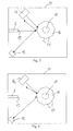
- the first detector 3 includes a component 14 at a reference temperature and a sensor 15 receiving the first optic signal from the first optic fibre 2 and a signal from the component 14 at the reference temperature and arranged to elaborate a signal indicative of the differential temperature between the temperature of a source of radiation detected via the first optic fibres 2 and the temperature of the component 14 at a reference temperature.
- the sensor 15 can for example be an infrared sensor (preferably a mid range infrared sensor).
- a wheel 16 is provided having a plurality of plane mirrors 17 over its whole circumference.
- the number of mirrors 17 is anyhow much higher, such as for example thirty, thirty two mirrors or more.
- the wheel 16 is connected to a motor 18 that makes it rotate at a high speed to achieve the required resolution.
- the wheel 16 is located in such a position facing the component 14, the first optic fibres 2 (in particular mouths 19 thereof opposite those mouths 12 at the collimator 11) and the sensor 15. While the wheel 16 rotates it reflects the first optic signal (coming from the first optic fibres 2) towards the sensor 15 ( figure 4 ) or the signal from the component 14 towards the same sensor 15 ( figure 3 ).
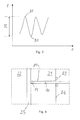
- the electric signal that is detected at the sensor 15 is schematically shown in figure 5 ; in this figure the points 30 correspond to the signal emitted by the component 14 and the points 31 correspond to the signal received through the first optic fibres 2 (i.e. the first optic signal); the positions in-between are due to the increasing and decreasing signal seen by the sensor 15 because of the rotation of the wheel 16.
- reference 32 indicates the signal indicative of the differential temperature.
- the senor 15 can include an electro optical modulating device like an acousto-optic modulator or a micro machine mechanical device (MEMS).
- an electro optical modulating device like an acousto-optic modulator or a micro machine mechanical device (MEMS).
- MEMS micro machine mechanical device
- the detector 3 has a housing 33 that is kept at a constant temperature (this temperature is the temperature of the component 14.
- the first process unit 4 can implement look up tables that associate the signal indicative of the differential temperature to the temperature of the component in front of the first fibre mouths 12.
- the first process unit 4 can be arranged to calculate the temperature of the source of the first optic signal in real time. This solution is preferred because at low temperatures the look up table gives large discretization. For example this can be done by calculating the Plank formula in real time.
- the second process unit 8 is arranged to measure a distance.
- the laser source, the optic process unit 6, the second detector 7 and the second process unit 8 can be similar to those described in EP 1 588 123 the content of which is included for reference.
- first fibres 2 and second fibre 5 do not include any active components; this is useful to avoid disturbances from the electric and magnetic fields usually present in an electric machines.
- the collimator 11 that is a lens does not include any active components.
- the materials of the collimator 11, sheath 10 optic fibres 2 and 5 is preferably a non metallic material; this hinders or reduces electromagnetic field influences.
- the operation of the monitoring device is substantially the following; the monitoring device is advantageously used to monitor an electric machine.
- One or more devices are applied on an electric machine (for example hydro generators, but also turbo generators, electric motors or other machines are possible).
- an electric machine for example hydro generators, but also turbo generators, electric motors or other machines are possible.
- they are preferably applied at different axial and/or circumferential positions.
- it is preferably applied at different axial and/or circumferential positions.
- Each device can give a measure of the whole circumference of the rotor.
- the collimator 11 and sheath 10 are introduced into a cooling channel 20 of a stator 21 of an electric machine, bringing the collimator 11 at the end of the cooling channel 20 at a position facing a rotor 22 and close to it, but not in contact with it.
- spacers 23 can be provided to predefine the positioning of the sheath 10.
- Spacers 23 can be elements that can slide on the sheath 10 and can be fixed to it (for example by screws), such that they are correctly located onto the sheath 10 and the sheath 10 is then introduced into a cooling channel 20 until the spacer 23 rests on the stator outside wall 24. Naturally also spacers fixed to the sheath 10 at a given position thereof can be provided.
- both these measures give indication of measures to counteract temperature increase or control the temperature in electric machines.
- the combination of the signals from the first and second optic fibres allows to have at the same time a high temperature resolution with an exact position (high space resolution).
- the gap width influences the circulation of the cooling fluid and therefore it indirectly influences the temperature of the stator and rotor part close to it.
- a large gap allows a large cooling fluid circulation and thus lower temperatures of stator and rotor part close to it.
Landscapes
- Physics & Mathematics (AREA)
- General Physics & Mathematics (AREA)
- Spectroscopy & Molecular Physics (AREA)
- Engineering & Computer Science (AREA)
- Microelectronics & Electronic Packaging (AREA)
- Power Engineering (AREA)
Priority Applications (4)
| Application Number | Priority Date | Filing Date | Title |
|---|---|---|---|
| ES11180962.0T ES2599397T3 (es) | 2011-09-12 | 2011-09-12 | Dispositivo de vigilancia de temperatura para motor eléctrico |
| SI201130997A SI2568583T1 (sl) | 2011-09-12 | 2011-09-12 | Naprava za nadzor temperature za elektro motorje |
| EP11180962.0A EP2568583B1 (fr) | 2011-09-12 | 2011-09-12 | Dispositif de surveillance de température pour un moteur éléctrique |
| PT111809620T PT2568583T (pt) | 2011-09-12 | 2011-09-12 | Dispositivo de monitorização de temperatura para motor elétrico |
Applications Claiming Priority (1)
| Application Number | Priority Date | Filing Date | Title |
|---|---|---|---|
| EP11180962.0A EP2568583B1 (fr) | 2011-09-12 | 2011-09-12 | Dispositif de surveillance de température pour un moteur éléctrique |
Publications (2)
| Publication Number | Publication Date |
|---|---|
| EP2568583A1 true EP2568583A1 (fr) | 2013-03-13 |
| EP2568583B1 EP2568583B1 (fr) | 2016-07-27 |
Family
ID=46980911
Family Applications (1)
| Application Number | Title | Priority Date | Filing Date |
|---|---|---|---|
| EP11180962.0A Not-in-force EP2568583B1 (fr) | 2011-09-12 | 2011-09-12 | Dispositif de surveillance de température pour un moteur éléctrique |
Country Status (4)
| Country | Link |
|---|---|
| EP (1) | EP2568583B1 (fr) |
| ES (1) | ES2599397T3 (fr) |
| PT (1) | PT2568583T (fr) |
| SI (1) | SI2568583T1 (fr) |
Cited By (2)
| Publication number | Priority date | Publication date | Assignee | Title |
|---|---|---|---|---|
| US10403116B2 (en) | 2017-06-20 | 2019-09-03 | General Electric Company | Electrical signature analysis of electrical rotating machines |
| US10928814B2 (en) | 2017-02-24 | 2021-02-23 | General Electric Technology Gmbh | Autonomous procedure for monitoring and diagnostics of machine based on electrical signature analysis |
Citations (7)
| Publication number | Priority date | Publication date | Assignee | Title |
|---|---|---|---|---|
| US3798366A (en) * | 1972-03-06 | 1974-03-19 | R Winkler | Infrared imaging system |
| DE2522621A1 (de) * | 1975-05-22 | 1976-11-25 | Walcher Elektromaschinenbau Kg | Elektrische maschine mit mindestens einem strahlungsempfaenger zur beruehrungslosen ueberwachung der laeufertemperatur |
| JPS6281619A (ja) * | 1985-10-07 | 1987-04-15 | Fujitsu Ltd | 赤外撮像用走査装置 |
| US4955979A (en) * | 1988-06-01 | 1990-09-11 | Electricite De France - Service National | Optical pyrometer with at least one fibre |
| JPH05296828A (ja) * | 1992-04-17 | 1993-11-12 | Nippon Avionics Co Ltd | 赤外線カメラ |
| EP0898158A2 (fr) | 1997-08-21 | 1999-02-24 | Abb Research Ltd. | Pyromètre optique pour une turbine à gaz |
| EP1588123A2 (fr) | 2003-01-30 | 2005-10-26 | Alstom Technology Ltd | Procede et appareil permettant de determiner la distance existant entre un objectif de collimateur et un objet |
-
2011
- 2011-09-12 SI SI201130997A patent/SI2568583T1/sl unknown
- 2011-09-12 PT PT111809620T patent/PT2568583T/pt unknown
- 2011-09-12 ES ES11180962.0T patent/ES2599397T3/es active Active
- 2011-09-12 EP EP11180962.0A patent/EP2568583B1/fr not_active Not-in-force
Patent Citations (8)
| Publication number | Priority date | Publication date | Assignee | Title |
|---|---|---|---|---|
| US3798366A (en) * | 1972-03-06 | 1974-03-19 | R Winkler | Infrared imaging system |
| DE2522621A1 (de) * | 1975-05-22 | 1976-11-25 | Walcher Elektromaschinenbau Kg | Elektrische maschine mit mindestens einem strahlungsempfaenger zur beruehrungslosen ueberwachung der laeufertemperatur |
| JPS6281619A (ja) * | 1985-10-07 | 1987-04-15 | Fujitsu Ltd | 赤外撮像用走査装置 |
| US4955979A (en) * | 1988-06-01 | 1990-09-11 | Electricite De France - Service National | Optical pyrometer with at least one fibre |
| JPH05296828A (ja) * | 1992-04-17 | 1993-11-12 | Nippon Avionics Co Ltd | 赤外線カメラ |
| EP0898158A2 (fr) | 1997-08-21 | 1999-02-24 | Abb Research Ltd. | Pyromètre optique pour une turbine à gaz |
| EP1588123A2 (fr) | 2003-01-30 | 2005-10-26 | Alstom Technology Ltd | Procede et appareil permettant de determiner la distance existant entre un objectif de collimateur et un objet |
| EP1588123B1 (fr) * | 2003-01-30 | 2007-06-06 | Alstom Technology Ltd | Procede et appareil permettant de determiner la distance existant entre l'anneau de renforcement d'une turbine et une extrémité d'une aube de turbine |
Non-Patent Citations (1)
| Title |
|---|
| AVDOSHIN E S: "A TWO-CHANNEL LIGHT-GUIDE IR RADIOMETER WITH SEMICONDUCTOR MODULATOR", MEASUREMENT TECHNIQUES, CONSULTANTS BUREAU. NEW YORK, US, vol. 34, no. 3, 1 March 1991 (1991-03-01), pages 233 - 236, XP000271348, ISSN: 0543-1972, DOI: 10.1007/BF00978790 * |
Cited By (2)
| Publication number | Priority date | Publication date | Assignee | Title |
|---|---|---|---|---|
| US10928814B2 (en) | 2017-02-24 | 2021-02-23 | General Electric Technology Gmbh | Autonomous procedure for monitoring and diagnostics of machine based on electrical signature analysis |
| US10403116B2 (en) | 2017-06-20 | 2019-09-03 | General Electric Company | Electrical signature analysis of electrical rotating machines |
Also Published As
| Publication number | Publication date |
|---|---|
| ES2599397T3 (es) | 2017-02-01 |
| EP2568583B1 (fr) | 2016-07-27 |
| PT2568583T (pt) | 2016-09-20 |
| SI2568583T1 (sl) | 2017-01-31 |
Similar Documents
| Publication | Publication Date | Title |
|---|---|---|
| EP3090269B1 (fr) | Système pour la surveillance de conditions d'une machine électrique, téléphone mobile et procédé associé | |
| CN104374491B (zh) | 一种防爆电机转子温度测量装置及方法 | |
| JP6256697B2 (ja) | 電動モータの温度計測装置 | |
| Bazzo et al. | Thermal imaging of hydroelectric generator stator using a DTS system | |
| Shang et al. | Fibre optic sensors for the monitoring of rotating electric machines: a review | |
| CN102405582B (zh) | 包括转子、定子和在转子与定子之间的空气间隙的电机 | |
| CN109115346A (zh) | 一种转动部件温度监测系统 | |
| Stone et al. | Using magnetic flux monitoring to detect synchronous machine rotor winding shorts | |
| Talas et al. | Dynamic measurement and analysis of air gap variations in large hydroelectric generators | |
| EP2568583B1 (fr) | Dispositif de surveillance de température pour un moteur éléctrique | |
| Mohammed et al. | In-situ thermal and mechanical fibre optic sensing for in-service electric machinery bearing condition monitoring | |
| Hind et al. | Use of optical fibres for multi-parameter monitoring in electrical AC machines | |
| US9160215B2 (en) | Monitoring the operating conditions of electric generators and motors by partial measurements | |
| BR102012000841A2 (pt) | Máquina elétrica, e, método para operar uma máquina elétrica | |
| CN204286635U (zh) | 一种防爆电机转子温度测量装置 | |
| KR102071275B1 (ko) | Rpm 신호를 이용한 발전기의 전압위상 검출 장치 | |
| Fabian et al. | Multi-parameter monitoring of electrical machines using integrated fibre Bragg gratings | |
| Wróblewski et al. | A multichannel measurement system for online turbogenerator vibration diagnostics | |
| Saad et al. | Space-time representation of the main air gap flux of a three phase squirrel cage induction motor and its application to detect eccentricity | |
| EP1906512A2 (fr) | Procédé et appareil pour la détection de court-circuits dans une machine électrique tournante | |
| CN114034488B (zh) | 用于发动机遥测仪器可靠性的试验系统及方法 | |
| JP2014522964A (ja) | パイロメータを備えたガスタービン | |
| KR20190117773A (ko) | 발전기, 측정 장치, 측정 장치의 사용, 발전기를 작동하기 위한 방법, 풍력 발전 설비 및 풍력 발전 설비를 작동하기 위한 방법 | |
| Singh et al. | Thermographical analysis of turbo-generator rotor | |
| Willsch et al. | Low temperature fiber optic pyrometer for fast time resolved temperature measurements |
Legal Events
| Date | Code | Title | Description |
|---|---|---|---|
| PUAI | Public reference made under article 153(3) epc to a published international application that has entered the european phase |
Free format text: ORIGINAL CODE: 0009012 |
|
| AK | Designated contracting states |
Kind code of ref document: A1 Designated state(s): AL AT BE BG CH CY CZ DE DK EE ES FI FR GB GR HR HU IE IS IT LI LT LU LV MC MK MT NL NO PL PT RO RS SE SI SK SM TR |
|
| AX | Request for extension of the european patent |
Extension state: BA ME |
|
| RAP1 | Party data changed (applicant data changed or rights of an application transferred) |
Owner name: ALSTOM RENEWABLE TECHNOLOGIES |
|
| 17P | Request for examination filed |
Effective date: 20130903 |
|
| RBV | Designated contracting states (corrected) |
Designated state(s): AL AT BE BG CH CY CZ DE DK EE ES FI FR GB GR HR HU IE IS IT LI LT LU LV MC MK MT NL NO PL PT RO RS SE SI SK SM TR |
|
| 17Q | First examination report despatched |
Effective date: 20131030 |
|
| GRAP | Despatch of communication of intention to grant a patent |
Free format text: ORIGINAL CODE: EPIDOSNIGR1 |
|
| INTG | Intention to grant announced |
Effective date: 20160115 |
|
| GRAS | Grant fee paid |
Free format text: ORIGINAL CODE: EPIDOSNIGR3 |
|
| GRAP | Despatch of communication of intention to grant a patent |
Free format text: ORIGINAL CODE: EPIDOSNIGR1 |
|
| INTG | Intention to grant announced |
Effective date: 20160503 |
|
| GRAA | (expected) grant |
Free format text: ORIGINAL CODE: 0009210 |
|
| AK | Designated contracting states |
Kind code of ref document: B1 Designated state(s): AL AT BE BG CH CY CZ DE DK EE ES FI FR GB GR HR HU IE IS IT LI LT LU LV MC MK MT NL NO PL PT RO RS SE SI SK SM TR |
|
| REG | Reference to a national code |
Ref country code: GB Ref legal event code: FG4D |
|
| REG | Reference to a national code |
Ref country code: CH Ref legal event code: EP |
|
| REG | Reference to a national code |
Ref country code: AT Ref legal event code: REF Ref document number: 816502 Country of ref document: AT Kind code of ref document: T Effective date: 20160815 |
|
| REG | Reference to a national code |
Ref country code: IE Ref legal event code: FG4D |
|
| REG | Reference to a national code |
Ref country code: DE Ref legal event code: R096 Ref document number: 602011028515 Country of ref document: DE |
|
| REG | Reference to a national code |
Ref country code: PT Ref legal event code: SC4A Ref document number: 2568583 Country of ref document: PT Date of ref document: 20160920 Kind code of ref document: T Free format text: AVAILABILITY OF NATIONAL TRANSLATION Effective date: 20160908 |
|
| REG | Reference to a national code |
Ref country code: FR Ref legal event code: PLFP Year of fee payment: 6 |
|
| REG | Reference to a national code |
Ref country code: LT Ref legal event code: MG4D |
|
| REG | Reference to a national code |
Ref country code: NL Ref legal event code: MP Effective date: 20160727 |
|
| REG | Reference to a national code |
Ref country code: NO Ref legal event code: T2 Effective date: 20160727 |
|
| PG25 | Lapsed in a contracting state [announced via postgrant information from national office to epo] |
Ref country code: RS Free format text: LAPSE BECAUSE OF FAILURE TO SUBMIT A TRANSLATION OF THE DESCRIPTION OR TO PAY THE FEE WITHIN THE PRESCRIBED TIME-LIMIT Effective date: 20160727 Ref country code: NL Free format text: LAPSE BECAUSE OF FAILURE TO SUBMIT A TRANSLATION OF THE DESCRIPTION OR TO PAY THE FEE WITHIN THE PRESCRIBED TIME-LIMIT Effective date: 20160727 Ref country code: FI Free format text: LAPSE BECAUSE OF FAILURE TO SUBMIT A TRANSLATION OF THE DESCRIPTION OR TO PAY THE FEE WITHIN THE PRESCRIBED TIME-LIMIT Effective date: 20160727 Ref country code: LT Free format text: LAPSE BECAUSE OF FAILURE TO SUBMIT A TRANSLATION OF THE DESCRIPTION OR TO PAY THE FEE WITHIN THE PRESCRIBED TIME-LIMIT Effective date: 20160727 Ref country code: HR Free format text: LAPSE BECAUSE OF FAILURE TO SUBMIT A TRANSLATION OF THE DESCRIPTION OR TO PAY THE FEE WITHIN THE PRESCRIBED TIME-LIMIT Effective date: 20160727 Ref country code: IS Free format text: LAPSE BECAUSE OF FAILURE TO SUBMIT A TRANSLATION OF THE DESCRIPTION OR TO PAY THE FEE WITHIN THE PRESCRIBED TIME-LIMIT Effective date: 20161127 |
|
| REG | Reference to a national code |
Ref country code: ES Ref legal event code: FG2A Ref document number: 2599397 Country of ref document: ES Kind code of ref document: T3 Effective date: 20170201 |
|
| PG25 | Lapsed in a contracting state [announced via postgrant information from national office to epo] |
Ref country code: PL Free format text: LAPSE BECAUSE OF FAILURE TO SUBMIT A TRANSLATION OF THE DESCRIPTION OR TO PAY THE FEE WITHIN THE PRESCRIBED TIME-LIMIT Effective date: 20160727 Ref country code: LV Free format text: LAPSE BECAUSE OF FAILURE TO SUBMIT A TRANSLATION OF THE DESCRIPTION OR TO PAY THE FEE WITHIN THE PRESCRIBED TIME-LIMIT Effective date: 20160727 Ref country code: BE Free format text: LAPSE BECAUSE OF NON-PAYMENT OF DUE FEES Effective date: 20160727 Ref country code: GR Free format text: LAPSE BECAUSE OF FAILURE TO SUBMIT A TRANSLATION OF THE DESCRIPTION OR TO PAY THE FEE WITHIN THE PRESCRIBED TIME-LIMIT Effective date: 20161028 Ref country code: SE Free format text: LAPSE BECAUSE OF FAILURE TO SUBMIT A TRANSLATION OF THE DESCRIPTION OR TO PAY THE FEE WITHIN THE PRESCRIBED TIME-LIMIT Effective date: 20160727 |
|
| PG25 | Lapsed in a contracting state [announced via postgrant information from national office to epo] |
Ref country code: RO Free format text: LAPSE BECAUSE OF FAILURE TO SUBMIT A TRANSLATION OF THE DESCRIPTION OR TO PAY THE FEE WITHIN THE PRESCRIBED TIME-LIMIT Effective date: 20160727 Ref country code: EE Free format text: LAPSE BECAUSE OF FAILURE TO SUBMIT A TRANSLATION OF THE DESCRIPTION OR TO PAY THE FEE WITHIN THE PRESCRIBED TIME-LIMIT Effective date: 20160727 Ref country code: MC Free format text: LAPSE BECAUSE OF FAILURE TO SUBMIT A TRANSLATION OF THE DESCRIPTION OR TO PAY THE FEE WITHIN THE PRESCRIBED TIME-LIMIT Effective date: 20160727 |
|
| REG | Reference to a national code |
Ref country code: CH Ref legal event code: PFA Owner name: GE RENEWABLE TECHNOLOGIES, FR Free format text: FORMER OWNER: ALSTOM RENEWABLE TECHNOLOGIES, FR |
|
| REG | Reference to a national code |
Ref country code: DE Ref legal event code: R097 Ref document number: 602011028515 Country of ref document: DE |
|
| PG25 | Lapsed in a contracting state [announced via postgrant information from national office to epo] |
Ref country code: SK Free format text: LAPSE BECAUSE OF FAILURE TO SUBMIT A TRANSLATION OF THE DESCRIPTION OR TO PAY THE FEE WITHIN THE PRESCRIBED TIME-LIMIT Effective date: 20160727 Ref country code: BG Free format text: LAPSE BECAUSE OF FAILURE TO SUBMIT A TRANSLATION OF THE DESCRIPTION OR TO PAY THE FEE WITHIN THE PRESCRIBED TIME-LIMIT Effective date: 20161027 Ref country code: DK Free format text: LAPSE BECAUSE OF FAILURE TO SUBMIT A TRANSLATION OF THE DESCRIPTION OR TO PAY THE FEE WITHIN THE PRESCRIBED TIME-LIMIT Effective date: 20160727 Ref country code: CZ Free format text: LAPSE BECAUSE OF FAILURE TO SUBMIT A TRANSLATION OF THE DESCRIPTION OR TO PAY THE FEE WITHIN THE PRESCRIBED TIME-LIMIT Effective date: 20160727 Ref country code: SM Free format text: LAPSE BECAUSE OF FAILURE TO SUBMIT A TRANSLATION OF THE DESCRIPTION OR TO PAY THE FEE WITHIN THE PRESCRIBED TIME-LIMIT Effective date: 20160727 |
|
| PLBE | No opposition filed within time limit |
Free format text: ORIGINAL CODE: 0009261 |
|
| STAA | Information on the status of an ep patent application or granted ep patent |
Free format text: STATUS: NO OPPOSITION FILED WITHIN TIME LIMIT |
|
| RAP2 | Party data changed (patent owner data changed or rights of a patent transferred) |
Owner name: GE RENEWABLE TECHNOLOGIES |
|
| REG | Reference to a national code |
Ref country code: IE Ref legal event code: MM4A |
|
| REG | Reference to a national code |
Ref country code: SI Ref legal event code: SP73 Owner name: GE RENEWABLE TECHNOLOGIES; FR Effective date: 20170519 |
|
| 26N | No opposition filed |
Effective date: 20170502 |
|
| PG25 | Lapsed in a contracting state [announced via postgrant information from national office to epo] |
Ref country code: IE Free format text: LAPSE BECAUSE OF NON-PAYMENT OF DUE FEES Effective date: 20160912 |
|
| REG | Reference to a national code |
Ref country code: AT Ref legal event code: HC Ref document number: 816502 Country of ref document: AT Kind code of ref document: T Owner name: GE RENEWABLE TECHNOLOGIES, FR Effective date: 20170630 |
|
| PG25 | Lapsed in a contracting state [announced via postgrant information from national office to epo] |
Ref country code: LU Free format text: LAPSE BECAUSE OF NON-PAYMENT OF DUE FEES Effective date: 20160912 |
|
| REG | Reference to a national code |
Ref country code: NO Ref legal event code: CHAD Owner name: GE RENEWABLE TECHNOLOGIES, FR Ref country code: NO Ref legal event code: CREP Representative=s name: BRYN AARFLOT AS, POSTBOKS 449 SENTRUM, 0104 OSLO |
|
| REG | Reference to a national code |
Ref country code: FR Ref legal event code: PLFP Year of fee payment: 7 |
|
| REG | Reference to a national code |
Ref country code: FR Ref legal event code: CD Owner name: GE RENEWABLE TECHNOLOGIES, FR Effective date: 20170929 |
|
| REG | Reference to a national code |
Ref country code: ES Ref legal event code: PC2A Owner name: GE RENEWABLE TECHNOLOGIES Effective date: 20180213 |
|
| PG25 | Lapsed in a contracting state [announced via postgrant information from national office to epo] |
Ref country code: CY Free format text: LAPSE BECAUSE OF FAILURE TO SUBMIT A TRANSLATION OF THE DESCRIPTION OR TO PAY THE FEE WITHIN THE PRESCRIBED TIME-LIMIT Effective date: 20160727 Ref country code: HU Free format text: LAPSE BECAUSE OF FAILURE TO SUBMIT A TRANSLATION OF THE DESCRIPTION OR TO PAY THE FEE WITHIN THE PRESCRIBED TIME-LIMIT; INVALID AB INITIO Effective date: 20110912 |
|
| PG25 | Lapsed in a contracting state [announced via postgrant information from national office to epo] |
Ref country code: MK Free format text: LAPSE BECAUSE OF FAILURE TO SUBMIT A TRANSLATION OF THE DESCRIPTION OR TO PAY THE FEE WITHIN THE PRESCRIBED TIME-LIMIT Effective date: 20160727 Ref country code: MT Free format text: LAPSE BECAUSE OF NON-PAYMENT OF DUE FEES Effective date: 20160930 |
|
| REG | Reference to a national code |
Ref country code: FR Ref legal event code: PLFP Year of fee payment: 8 |
|
| PG25 | Lapsed in a contracting state [announced via postgrant information from national office to epo] |
Ref country code: AL Free format text: LAPSE BECAUSE OF FAILURE TO SUBMIT A TRANSLATION OF THE DESCRIPTION OR TO PAY THE FEE WITHIN THE PRESCRIBED TIME-LIMIT Effective date: 20160727 |
|
| PGFP | Annual fee paid to national office [announced via postgrant information from national office to epo] |
Ref country code: IT Payment date: 20180828 Year of fee payment: 8 Ref country code: NO Payment date: 20180824 Year of fee payment: 8 Ref country code: FR Payment date: 20180822 Year of fee payment: 8 Ref country code: DE Payment date: 20180821 Year of fee payment: 8 |
|
| PGFP | Annual fee paid to national office [announced via postgrant information from national office to epo] |
Ref country code: SI Payment date: 20180827 Year of fee payment: 8 Ref country code: CH Payment date: 20180828 Year of fee payment: 8 Ref country code: GB Payment date: 20180823 Year of fee payment: 8 Ref country code: AT Payment date: 20180822 Year of fee payment: 8 Ref country code: TR Payment date: 20180903 Year of fee payment: 8 |
|
| PGFP | Annual fee paid to national office [announced via postgrant information from national office to epo] |
Ref country code: PT Payment date: 20180903 Year of fee payment: 8 |
|
| PGFP | Annual fee paid to national office [announced via postgrant information from national office to epo] |
Ref country code: ES Payment date: 20181001 Year of fee payment: 8 |
|
| REG | Reference to a national code |
Ref country code: AT Ref legal event code: UEP Ref document number: 816502 Country of ref document: AT Kind code of ref document: T Effective date: 20160727 |
|
| REG | Reference to a national code |
Ref country code: DE Ref legal event code: R119 Ref document number: 602011028515 Country of ref document: DE |
|
| REG | Reference to a national code |
Ref country code: NO Ref legal event code: MMEP |
|
| PG25 | Lapsed in a contracting state [announced via postgrant information from national office to epo] |
Ref country code: PT Free format text: LAPSE BECAUSE OF NON-PAYMENT OF DUE FEES Effective date: 20200312 |
|
| REG | Reference to a national code |
Ref country code: CH Ref legal event code: PL |
|
| PG25 | Lapsed in a contracting state [announced via postgrant information from national office to epo] |
Ref country code: DE Free format text: LAPSE BECAUSE OF NON-PAYMENT OF DUE FEES Effective date: 20200401 Ref country code: NO Free format text: LAPSE BECAUSE OF NON-PAYMENT OF DUE FEES Effective date: 20190930 Ref country code: LI Free format text: LAPSE BECAUSE OF NON-PAYMENT OF DUE FEES Effective date: 20190930 Ref country code: PT Free format text: LAPSE BECAUSE OF NON-PAYMENT OF DUE FEES Effective date: 20200422 Ref country code: CH Free format text: LAPSE BECAUSE OF NON-PAYMENT OF DUE FEES Effective date: 20190930 |
|
| REG | Reference to a national code |
Ref country code: AT Ref legal event code: MM01 Ref document number: 816502 Country of ref document: AT Kind code of ref document: T Effective date: 20190912 |
|
| PG25 | Lapsed in a contracting state [announced via postgrant information from national office to epo] |
Ref country code: SI Free format text: LAPSE BECAUSE OF NON-PAYMENT OF DUE FEES Effective date: 20190913 Ref country code: IT Free format text: LAPSE BECAUSE OF NON-PAYMENT OF DUE FEES Effective date: 20190912 |
|
| REG | Reference to a national code |
Ref country code: SI Ref legal event code: KO00 Effective date: 20200722 |
|
| GBPC | Gb: european patent ceased through non-payment of renewal fee |
Effective date: 20190912 |
|
| PG25 | Lapsed in a contracting state [announced via postgrant information from national office to epo] |
Ref country code: FR Free format text: LAPSE BECAUSE OF NON-PAYMENT OF DUE FEES Effective date: 20190930 Ref country code: GB Free format text: LAPSE BECAUSE OF NON-PAYMENT OF DUE FEES Effective date: 20190912 |
|
| PG25 | Lapsed in a contracting state [announced via postgrant information from national office to epo] |
Ref country code: AT Free format text: LAPSE BECAUSE OF NON-PAYMENT OF DUE FEES Effective date: 20190912 |
|
| REG | Reference to a national code |
Ref country code: ES Ref legal event code: FD2A Effective date: 20210127 |
|
| PG25 | Lapsed in a contracting state [announced via postgrant information from national office to epo] |
Ref country code: ES Free format text: LAPSE BECAUSE OF NON-PAYMENT OF DUE FEES Effective date: 20190913 |
|
| PG25 | Lapsed in a contracting state [announced via postgrant information from national office to epo] |
Ref country code: TR Free format text: LAPSE BECAUSE OF NON-PAYMENT OF DUE FEES Effective date: 20190912 |