EP2568584A2 - Systéme de mise à la terre d'un arbre de machine électrique - Google Patents
Systéme de mise à la terre d'un arbre de machine électrique Download PDFInfo
- Publication number
- EP2568584A2 EP2568584A2 EP20120182471 EP12182471A EP2568584A2 EP 2568584 A2 EP2568584 A2 EP 2568584A2 EP 20120182471 EP20120182471 EP 20120182471 EP 12182471 A EP12182471 A EP 12182471A EP 2568584 A2 EP2568584 A2 EP 2568584A2
- Authority
- EP
- European Patent Office
- Prior art keywords
- shaft
- component
- inner component
- ground
- grounding system
- Prior art date
- Legal status (The legal status is an assumption and is not a legal conclusion. Google has not performed a legal analysis and makes no representation as to the accuracy of the status listed.)
- Withdrawn
Links
- 239000000126 substance Substances 0.000 claims abstract description 20
- 230000000295 complement effect Effects 0.000 claims abstract description 9
- 238000010248 power generation Methods 0.000 claims description 6
- 239000004519 grease Substances 0.000 claims description 3
- 239000012530 fluid Substances 0.000 description 8
- OKTJSMMVPCPJKN-UHFFFAOYSA-N Carbon Chemical compound [C] OKTJSMMVPCPJKN-UHFFFAOYSA-N 0.000 description 4
- 239000000428 dust Substances 0.000 description 3
- 229920000049 Carbon (fiber) Polymers 0.000 description 2
- 239000004917 carbon fiber Substances 0.000 description 2
- 239000000314 lubricant Substances 0.000 description 2
- 238000009825 accumulation Methods 0.000 description 1
- 230000004927 fusion Effects 0.000 description 1
- 239000000499 gel Substances 0.000 description 1
- 230000001788 irregular Effects 0.000 description 1
- 238000003754 machining Methods 0.000 description 1
- 238000000034 method Methods 0.000 description 1
- 238000012544 monitoring process Methods 0.000 description 1
- 239000003921 oil Substances 0.000 description 1
- 238000011084 recovery Methods 0.000 description 1
- 238000007789 sealing Methods 0.000 description 1
- 239000007787 solid Substances 0.000 description 1
- XLYOFNOQVPJJNP-UHFFFAOYSA-N water Substances O XLYOFNOQVPJJNP-UHFFFAOYSA-N 0.000 description 1
- 238000003466 welding Methods 0.000 description 1
Images


Classifications
-
- H—ELECTRICITY
- H02—GENERATION; CONVERSION OR DISTRIBUTION OF ELECTRIC POWER
- H02K—DYNAMO-ELECTRIC MACHINES
- H02K11/00—Structural association of dynamo-electric machines with electric components or with devices for shielding, monitoring or protection
- H02K11/40—Structural association with grounding devices
-
- H—ELECTRICITY
- H01—ELECTRIC ELEMENTS
- H01R—ELECTRICALLY-CONDUCTIVE CONNECTIONS; STRUCTURAL ASSOCIATIONS OF A PLURALITY OF MUTUALLY-INSULATED ELECTRICAL CONNECTING ELEMENTS; COUPLING DEVICES; CURRENT COLLECTORS
- H01R39/00—Rotary current collectors, distributors or interrupters
- H01R39/64—Devices for uninterrupted current collection
- H01R39/646—Devices for uninterrupted current collection through an electrical conductive fluid
-
- H—ELECTRICITY
- H02—GENERATION; CONVERSION OR DISTRIBUTION OF ELECTRIC POWER
- H02K—DYNAMO-ELECTRIC MACHINES
- H02K5/00—Casings; Enclosures; Supports
- H02K5/04—Casings or enclosures characterised by the shape, form or construction thereof
- H02K5/16—Means for supporting bearings, e.g. insulating supports or means for fitting bearings in the bearing-shields
- H02K5/173—Means for supporting bearings, e.g. insulating supports or means for fitting bearings in the bearing-shields using bearings with rolling contact, e.g. ball bearings
- H02K5/1732—Means for supporting bearings, e.g. insulating supports or means for fitting bearings in the bearing-shields using bearings with rolling contact, e.g. ball bearings radially supporting the rotary shaft at both ends of the rotor
-
- Y—GENERAL TAGGING OF NEW TECHNOLOGICAL DEVELOPMENTS; GENERAL TAGGING OF CROSS-SECTIONAL TECHNOLOGIES SPANNING OVER SEVERAL SECTIONS OF THE IPC; TECHNICAL SUBJECTS COVERED BY FORMER USPC CROSS-REFERENCE ART COLLECTIONS [XRACs] AND DIGESTS
- Y02—TECHNOLOGIES OR APPLICATIONS FOR MITIGATION OR ADAPTATION AGAINST CLIMATE CHANGE
- Y02E—REDUCTION OF GREENHOUSE GAS [GHG] EMISSIONS, RELATED TO ENERGY GENERATION, TRANSMISSION OR DISTRIBUTION
- Y02E20/00—Combustion technologies with mitigation potential
- Y02E20/16—Combined cycle power plant [CCPP], or combined cycle gas turbine [CCGT]
Definitions
- the subject matter disclosed herein relates to machine shafts and, more particularly, to a system for electrically grounding rotating shafts in machines, particularly dynamoelectric machines.
- Some machines e.g., dynamoelectric machines, generators, alternating current motors, direct current motors etc.
- rotary shafts may be physically connected to portions of the machine and supported by bearings. In operation, some of these shafts may develop and/or receive unwanted electrical voltages. These voltages may discharge from the shaft through portions of the machine (e.g., bearings), causing fusion craters, severe pitting, fluting damage, bearing failure, etc. Therefore, it is desirable to preemptively dissipate and/or release these unwanted electrical voltages in a controlled manner, thereby avoiding damage to machine components.
- Some machines use grounded brush seals and/or carbon fibers disposed around and physically in contact with the rotary shaft to ground the unwanted electrical voltages. These systems are machined to fit precisely about the shaft and include conductive elements which are physically in contact with both the rotating shaft and an electrically grounded component. However, these systems may require special machining to attain a proper fit, and as a result of the requisite physical contact may wear, degrade, produce dust and generate sparks during operation.
- a system includes: an inner component configured to be connected to a shaft; a ground component configured to be disposed substantially about the inner component, the ground component configured to complement the inner component and substantially define a cavity there between; and a conductive substance disposed within the cavity substantially between the inner component and the ground component, the conductive substance configured to electrically connect the inner component and the ground component.
- a first aspect of the invention provides a system including: an inner component configured to be connected to a shaft; a ground component configured to be disposed substantially about the inner component, the ground component configured to complement the inner component and substantially define a cavity there between; and a conductive substance disposed within the cavity substantially between the inner component and the ground component, the conductive substance configured to electrically connect the inner component and the ground component.
- a second aspect provides a dynamoelectric machine including: a stator; a rotor disposed substantially within the stator, the rotor including a shaft; and a grounding system disposed circumferentially about a portion of the shaft, the grounding system comprising: an inner component configured to be connected to a shaft; a ground component configured to be disposed substantially about the inner component, the ground component configured to complement the inner component and substantially define a cavity there between; and a conductive substance disposed within the cavity substantially between the inner component and the ground component, the conductive substance configured to electrically connect the inner component and the ground component.
- a third aspect provides a power generation system including: a turbine; a generator operatively connected to the turbine, the generator including a shaft; and a grounding system disposed circumferentially about a portion of the shaft, the grounding system comprising: an inner component configured to be connected to a shaft; a ground component configured to be disposed substantially about the inner component, the ground component configured to complement the inner component and substantially define a cavity there between; and a conductive substance disposed within the cavity substantially between the inner component and the ground component, the conductive substance configured to electrically connect the inner component and the ground component.
- aspects of the invention provide for systems configured to electrically ground rotating components in a machine, (for example, e.g. a driving machine, a dynamoelectric machine, an alternating current motor, a generator, a direct current motor, a gas turbine, a steam turbine, a compressor, etc.).
- a machine for example, e.g. a driving machine, a dynamoelectric machine, an alternating current motor, a generator, a direct current motor, a gas turbine, a steam turbine, a compressor, etc.
- a conductive substance e.g., fluid, grease, gel, carbon powder, graphite powder etc.
- Some machines and/or systems may induce harmful electrical voltages in the shafts of these machines. These harmful voltages may discharge through the machine and cause component damage such as craters, pitting, fluting, component failure, etc.
- Some systems use grounded brush seals or carbon fibers which are physically connected to the shaft during operation to dissipate these harmful voltages. However, during operation these dissipation systems may produce dust, generate sparks, wear on the machine components, and require continuous monitoring.
- inventions of the current invention provide for a system which electrically grounds a rotating shaft without producing dust, sparks or wear on machine components.
- the system includes an inner component which is disposed substantially about and physically connected to the rotating shaft.
- the inner component is electrically connected, via a conductive substance and/or fluid, to a ground component which is configured to complement the inner component.
- the ground component and inner component are configured relative one another so as to substantially define a cavity between the ground component and the inner component which contains the conductive fluid.
- the inner component may rotate with the shaft and remain electrically connected to the ground component via the conductive fluid.
- harmful voltages that develop or accumulate on the shaft may be safely discharged to the ground component through the conductive fluid before attaining a level that may be harmful to machine components.
- FIG. 1 a partial cross-sectional view of portions of a machine 100 in accordance with an aspect of the invention is shown.
- Machine 100 may include a shaft 104 operably connected to a motor 102 and electrically connected to a grounding system 110.
- motor 102 may rotate and/or operate shaft 104, which may induce or cause the accumulation of harmful electrical voltages within shaft 104.
- grounding system 110 which is physically connected to a grounded surface 112 via a wire 111.
- Grounding system 110 dissipates these received electrical voltages to ground 112 via wire 111.
- grounding system 110 is physically connected to a portion of shaft 104.
- grounding system 110 is configured circumferentially about a portion of shaft 104.
- grounding system 110 has a substantially annular shape.
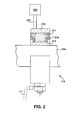
- grounding system 110 may include a ground component 216 configured substantially about an inner component 214 which may be configured to be disposed upon shaft 104.
- inner component 214 is physically connected to shaft 104, such that rotation of shaft 104 substantially rotates inner component 214.
- inner component 214 is integral to shaft 104.
- inner component 214 may have a ring shape.
- inner component 214 may have an irregular shape.
- ground component 216 may be configured to be disposed circumferentially about both inner component 214 and a portion of shaft 104.
- ground component 216 is complementary to inner component 214 and configured in substantial proximity to inner component 214 so as to substantially define a cavity 217 there between ground component 216 and inner component 214.
- ground component 216 and inner component 214 may be physically independent of one another.
- ground component 216 and inner component 214 may be configured to maintain a physical clearance there between one another.
- ground component 216 and inner component 214 may physically contact one another.
- a conductive substance may be disposed within cavity 217, thereby electrically connecting inner component 214 and ground component 216.
- the conductive substance may be a solid conductive lubricant (e.g., carbon powder, graphite powder, etc.).
- the conductive substance may be a conductive fluid (e.g., grease, oil, lubricant, etc.).
- the conductive fluid substantially fills cavity 217 such that inner component 214 and ground component 216 are in substantially continuous electrical contact.
- a seal 218 may be disposed between inner component 214 and ground component 216. Seal 218 further defining cavity 217 and substantially sealing the conductive substance between inner component 214 and ground component 216. It is understood that seal 218 may comprise any kind of seal as is known, such as an overlap seal, a labyrinth seal, etc.
- grounding system 110 includes a sensor 222 which is operably connected to ground component 216 via a wire 220.
- Sensor 222 may be configured to measure at least one of: a current in the shaft, a voltage in the shaft, a temperature of the shaft, a temperature of the inner component, or a temperature of the electrically conductive fluid.
- grounding system assembly 300 includes a plurality of grounding systems 110 which are connected to a shaft 104.
- sensor 222 may be operably connected to a grounding system 110 to obtain data readings from shaft 104.
- a grounded surface 112 may be electrically connected to remaining grounding systems 110 to dissipate electrical currents from shaft 104.
- each grounding system 110 may dissipate currents from shaft 104 and be connected to sensor 222 such that each grounding system 110 obtains data readings from shaft 104 via sensor 222.
- each grounding system 110 dissipates a specific area of shaft 104 and obtains location specific data readings of shaft 104.
- Combined-cycle power plant 510 may include, for example, a gas turbine 542 operably connected to a generator 544.
- Generator 544 and gas turbine 542 may be mechanically coupled by a shaft 511, which may transfer energy between a drive shaft (not shown) of gas turbine 542 and generator 544.
- Generator 544 and/or shaft 511 may be operably connected to grounding system 110 of FIG. 1 or other embodiments described herein.
- a heat exchanger 546 operably connected to gas turbine 542 and a steam turbine 548.
- Heat exchanger 546 may be fluidly connected to both gas turbine 542 and steam turbine 548 via conventional conduits (numbering omitted).
- Heat exchanger 546 may be a conventional heat recovery steam generator (HRSG), such as those used in conventional combined-cycle power systems.
- HRSG 546 may use hot exhaust from gas turbine 542, combined with a water supply, to create steam which is fed to steam turbine 548.
- Steam turbine 548 may optionally be coupled to a second generator system 544 (via a second shaft 511). It is understood that generators 544 and shafts 511 may be of any size or type known in the art and may differ depending upon their application or the system to which they are connected.
- Generator system 544 and second shaft 511 may operate substantially similarly to generator system 544 and shaft 511 described above, and further may also be operably connected to grounding system 110 of FIG. 1 or other embodiments described herein.
- Steam turbine 548 may be fluidly connected to grounding system 110 of FIG. 1 or other embodiments described herein.
- a single-shaft combined-cycle power plant 590 may include a single generator 544 coupled to both gas turbine 542 and steam turbine 546 via a single shaft 511.
- Single generator 544 and single shaft 511 may be fluidly connected to grounding system 110 of FIG. 1 or other embodiments described herein.
- grounding system of the present disclosure is not limited to any one particular machine, driven machine, turbine, fan, blower, compressor, power generation system or other system, and may be used with other power generation systems and/or systems (e.g., combined-cycle, simple-cycle, nuclear reactor, etc.). Additionally, the grounding system of the present invention may be used with other systems not described herein that may benefit from the electrical dissipation/grounding/release capabilities of the grounding system described herein.
Landscapes
- Engineering & Computer Science (AREA)
- Power Engineering (AREA)
- Motor Or Generator Frames (AREA)
Applications Claiming Priority (1)
| Application Number | Priority Date | Filing Date | Title |
|---|---|---|---|
| US13/227,193 US9088197B2 (en) | 2011-09-07 | 2011-09-07 | Shaft grounding system |
Publications (2)
| Publication Number | Publication Date |
|---|---|
| EP2568584A2 true EP2568584A2 (fr) | 2013-03-13 |
| EP2568584A3 EP2568584A3 (fr) | 2016-08-24 |
Family
ID=47137493
Family Applications (1)
| Application Number | Title | Priority Date | Filing Date |
|---|---|---|---|
| EP12182471.8A Withdrawn EP2568584A3 (fr) | 2011-09-07 | 2012-08-30 | Systéme de mise à la terre d'un arbre de machine électrique |
Country Status (2)
| Country | Link |
|---|---|
| US (1) | US9088197B2 (fr) |
| EP (1) | EP2568584A3 (fr) |
Families Citing this family (8)
| Publication number | Priority date | Publication date | Assignee | Title |
|---|---|---|---|---|
| US9160216B2 (en) * | 2013-03-14 | 2015-10-13 | Regal Beloit America, Inc. | Grounding device for electric machine and methods of assembling the same |
| US10371726B2 (en) * | 2016-01-11 | 2019-08-06 | Cutsforth, Inc. | Monitoring system for grounding apparatus |
| US11162591B2 (en) | 2016-03-10 | 2021-11-02 | General Electric Company | Seal ring assembly for a dynamoelectric machine |
| DE102016216909A1 (de) * | 2016-09-06 | 2018-03-08 | Bayerische Motoren Werke Aktiengesellschaft | Antriebseinrichtung für ein Kraftfahrzeug, insbesondere einen Kraftwagen, sowie Kraftfahrzeug mit einer solchen Antriebseinrichtung |
| US20180195407A1 (en) * | 2017-01-12 | 2018-07-12 | Pratt & Whitney Canada Corp. | Aircraft engine having seal assembly defining an electrically conductive path |
| CA3062707C (fr) | 2017-06-05 | 2023-03-14 | Cutsforth, Inc. | Systeme de surveillance d'un appareil de mise a la terre |
| US10814889B2 (en) * | 2017-10-09 | 2020-10-27 | Trackmobile Llc | Modular drive train for railcar mover |
| CN109037985B (zh) * | 2018-07-11 | 2020-02-28 | 国网吉林省电力有限公司四平供电公司 | 一种多端防脱接地装置 |
Family Cites Families (24)
| Publication number | Priority date | Publication date | Assignee | Title |
|---|---|---|---|---|
| GB1456313A (en) * | 1974-03-27 | 1976-11-24 | Electricity Council | Electrical connections |
| US4873512A (en) | 1984-03-20 | 1989-10-10 | Westinghouse Electric Corp. | Active shaft grounding and diagnotic system |
| US4746297A (en) * | 1985-04-02 | 1988-05-24 | Soleau James R | Rotative electrical connector |
| US4661734A (en) * | 1985-09-10 | 1987-04-28 | General Electric Company | Dynamoelectric machine |
| CH674433A5 (fr) * | 1986-11-19 | 1990-05-31 | Bbc Brown Boveri & Cie | |
| US4801270A (en) | 1987-10-05 | 1989-01-31 | Xerox Corporation | Shaft mounting and electrical grounding device |
| US4954084A (en) | 1989-09-06 | 1990-09-04 | Marine Hardware, Inc. | Shaft-grounding stuffing box cover |
| US5227950A (en) | 1991-03-01 | 1993-07-13 | Westinghouse Electric Corp. | Shaft grounding brush and holder |
| IT1293461B1 (it) * | 1997-07-17 | 1999-03-01 | Skf Ind Spa | Cuscinetto di rotolamento con dispositivo di tenuta e di scarico di correnti elettrostatiche. |
| US5914547A (en) * | 1997-11-21 | 1999-06-22 | Magnetek, Inc. | Auxiliary bearing assembly for reduction of unwanted shaft voltages in an electric motor |
| JPH11270554A (ja) * | 1998-03-20 | 1999-10-05 | Kawasaki Steel Corp | 被加熱軸の軸受回転不良防止方法及び装置 |
| US6093986A (en) * | 1999-03-08 | 2000-07-25 | Emerson Electric Co. | Method and apparatus for powering shaft-mounted sensors on motors and generators |
| US6460013B1 (en) * | 1999-05-06 | 2002-10-01 | Paul I. Nippes | Shaft voltage current monitoring system for early warning and problem detection |
| KR100491692B1 (ko) * | 1999-11-15 | 2005-05-25 | 미쓰비시덴키 가부시키가이샤 | 회전베어링 |
| JP2001320849A (ja) | 2000-02-29 | 2001-11-16 | Asmo Co Ltd | モータ |
| US20020121821A1 (en) * | 2001-03-02 | 2002-09-05 | Ritter Allen Michael | Method and apparatus for reducing bearing current in a motor and/or generator |
| US6670733B2 (en) * | 2001-09-27 | 2003-12-30 | Reliance Electric Technologies, Llc | System and method of reducing bearing voltage |
| US7649470B2 (en) * | 2002-09-10 | 2010-01-19 | Alstom Technology Ltd. | Method and apparatus for detection of brush sparking and spark erosion on electrical machines |
| US7193836B2 (en) * | 2003-03-17 | 2007-03-20 | Illinois Tool Works Inc | Grounding brush for mitigating electrical current on motor shafts |
| JP2005017147A (ja) * | 2003-06-27 | 2005-01-20 | Ntn Corp | 転がり軸受の内輪温度測定装置 |
| US20050062350A1 (en) | 2003-08-21 | 2005-03-24 | A.O. Smith Corporation | Conductive greases and methods for using conductive greases in motors |
| US7339777B2 (en) | 2006-01-12 | 2008-03-04 | Illinois Tool Works Inc | Grounding system for a rotating shaft |
| EP1996815B2 (fr) * | 2006-03-17 | 2024-02-14 | Vestas Wind Systems A/S | Eolienne avec un systeme de protection pour generateur electrique et son utilisation |
| FR2933544B1 (fr) * | 2008-07-03 | 2016-05-06 | Alstom Transport Sa | Machine comprenant un dispositif de continuite electrique entre sa structure porteuse et son arbre |
-
2011
- 2011-09-07 US US13/227,193 patent/US9088197B2/en not_active Expired - Fee Related
-
2012
- 2012-08-30 EP EP12182471.8A patent/EP2568584A3/fr not_active Withdrawn
Non-Patent Citations (1)
| Title |
|---|
| None |
Also Published As
| Publication number | Publication date |
|---|---|
| US20130057108A1 (en) | 2013-03-07 |
| US9088197B2 (en) | 2015-07-21 |
| EP2568584A3 (fr) | 2016-08-24 |
Similar Documents
| Publication | Publication Date | Title |
|---|---|---|
| US9088197B2 (en) | Shaft grounding system | |
| AU2010303017B2 (en) | A hydroelectric turbine with coil cooling | |
| JP6952476B2 (ja) | ダイナモエレクトリック機械用のシールリング組立体 | |
| US7112036B2 (en) | Rotor and bearing system for a turbomachine | |
| EP2916438B1 (fr) | Turbine électrique et centrale électrique | |
| CN112534657B (zh) | 滑环、滑环单元、电机与风力发电设施 | |
| EP1586742A2 (fr) | Procédé et dispositif pour réduire le flux d'auto-étanchéité dans les turbines à vapeur à cycle combiné | |
| WO2014090251A1 (fr) | Machine électrique tournante ayant une meilleure lubrification de palier et procédés s'y rapportant | |
| US20160172931A1 (en) | Alternator rotor to stator integrated hrdrodynamic bearing | |
| US10476356B2 (en) | Maintaining double feed induction generator wye ring | |
| CN100404819C (zh) | 促进涡轮回转轴之间密封的装置 | |
| JP5447677B2 (ja) | 廃熱発電装置 | |
| EP2747255B1 (fr) | Rotor pour machine électrique | |
| EP3038238B1 (fr) | Rotor pour machine électrique tournante | |
| US20120098383A1 (en) | Electric Machine Having a Brush-Slip Ring Device | |
| US20120201661A1 (en) | Contaminant shield system for a shaft | |
| US8998588B2 (en) | Segmented fan assembly | |
| EP3767800B1 (fr) | Machine électrique | |
| JP5105838B2 (ja) | 給電装置 | |
| JP5227814B2 (ja) | 電動機 | |
| JP2012039816A (ja) | 発電装置及び発電システム | |
| CN104712376A (zh) | 轴向面向密封系统、转子及涡轮机 | |
| EP2696479A1 (fr) | Procédé de fabrication d'un agencement de flasque de machine électrique tournante, agencement de flasque de machine électrique tournante et machine électrique tournante | |
| CN108288879A (zh) | 用于电机的定子支承 | |
| CN112879231A (zh) | 组装用于电机的具有改善刚度的传动系的方法 |
Legal Events
| Date | Code | Title | Description |
|---|---|---|---|
| PUAI | Public reference made under article 153(3) epc to a published international application that has entered the european phase |
Free format text: ORIGINAL CODE: 0009012 |
|
| AK | Designated contracting states |
Kind code of ref document: A2 Designated state(s): AL AT BE BG CH CY CZ DE DK EE ES FI FR GB GR HR HU IE IS IT LI LT LU LV MC MK MT NL NO PL PT RO RS SE SI SK SM TR |
|
| AX | Request for extension of the european patent |
Extension state: BA ME |
|
| PUAL | Search report despatched |
Free format text: ORIGINAL CODE: 0009013 |
|
| AK | Designated contracting states |
Kind code of ref document: A3 Designated state(s): AL AT BE BG CH CY CZ DE DK EE ES FI FR GB GR HR HU IE IS IT LI LT LU LV MC MK MT NL NO PL PT RO RS SE SI SK SM TR |
|
| AX | Request for extension of the european patent |
Extension state: BA ME |
|
| RIC1 | Information provided on ipc code assigned before grant |
Ipc: H01R 39/64 20060101ALN20160719BHEP Ipc: H02K 11/00 20160101AFI20160719BHEP |
|
| 17P | Request for examination filed |
Effective date: 20170220 |
|
| RBV | Designated contracting states (corrected) |
Designated state(s): AL AT BE BG CH CY CZ DE DK EE ES FI FR GB GR HR HU IE IS IT LI LT LU LV MC MK MT NL NO PL PT RO RS SE SI SK SM TR |
|
| 17Q | First examination report despatched |
Effective date: 20170426 |
|
| STAA | Information on the status of an ep patent application or granted ep patent |
Free format text: STATUS: THE APPLICATION IS DEEMED TO BE WITHDRAWN |
|
| 18D | Application deemed to be withdrawn |
Effective date: 20171107 |