EP2569242B2 - Riemen für die antriebstechnik, insbesondere riemenartiges zugelement für die aufzugstechnik, mit brandhemmenden eigenschaften - Google Patents
Riemen für die antriebstechnik, insbesondere riemenartiges zugelement für die aufzugstechnik, mit brandhemmenden eigenschaften Download PDFInfo
- Publication number
- EP2569242B2 EP2569242B2 EP10755164.0A EP10755164A EP2569242B2 EP 2569242 B2 EP2569242 B2 EP 2569242B2 EP 10755164 A EP10755164 A EP 10755164A EP 2569242 B2 EP2569242 B2 EP 2569242B2
- Authority
- EP
- European Patent Office
- Prior art keywords
- belt
- fire
- weight
- retardant additive
- substructure
- Prior art date
- Legal status (The legal status is an assumption and is not a legal conclusion. Google has not performed a legal analysis and makes no representation as to the accuracy of the status listed.)
- Active
Links
Images

Classifications
-
- B—PERFORMING OPERATIONS; TRANSPORTING
- B66—HOISTING; LIFTING; HAULING
- B66B—ELEVATORS; ESCALATORS OR MOVING WALKWAYS
- B66B7/00—Other common features of elevators
- B66B7/06—Arrangements of ropes or cables
- B66B7/062—Belts
-
- D—TEXTILES; PAPER
- D07—ROPES; CABLES OTHER THAN ELECTRIC
- D07B—ROPES OR CABLES IN GENERAL
- D07B1/00—Constructional features of ropes or cables
- D07B1/16—Ropes or cables with an enveloping sheathing or inlays of rubber or plastics
- D07B1/162—Ropes or cables with an enveloping sheathing or inlays of rubber or plastics characterised by a plastic or rubber enveloping sheathing
-
- D—TEXTILES; PAPER
- D07—ROPES; CABLES OTHER THAN ELECTRIC
- D07B—ROPES OR CABLES IN GENERAL
- D07B1/00—Constructional features of ropes or cables
- D07B1/16—Ropes or cables with an enveloping sheathing or inlays of rubber or plastics
- D07B1/165—Ropes or cables with an enveloping sheathing or inlays of rubber or plastics characterised by a plastic or rubber inlay
-
- F—MECHANICAL ENGINEERING; LIGHTING; HEATING; WEAPONS; BLASTING
- F16—ENGINEERING ELEMENTS AND UNITS; GENERAL MEASURES FOR PRODUCING AND MAINTAINING EFFECTIVE FUNCTIONING OF MACHINES OR INSTALLATIONS; THERMAL INSULATION IN GENERAL
- F16G—BELTS, CABLES, OR ROPES, PREDOMINANTLY USED FOR DRIVING PURPOSES; CHAINS; FITTINGS PREDOMINANTLY USED THEREFOR
- F16G1/00—Driving-belts
- F16G1/06—Driving-belts made of rubber
- F16G1/08—Driving-belts made of rubber with reinforcement bonded by the rubber
- F16G1/12—Driving-belts made of rubber with reinforcement bonded by the rubber with metal reinforcement
-
- F—MECHANICAL ENGINEERING; LIGHTING; HEATING; WEAPONS; BLASTING
- F16—ENGINEERING ELEMENTS AND UNITS; GENERAL MEASURES FOR PRODUCING AND MAINTAINING EFFECTIVE FUNCTIONING OF MACHINES OR INSTALLATIONS; THERMAL INSULATION IN GENERAL
- F16G—BELTS, CABLES, OR ROPES, PREDOMINANTLY USED FOR DRIVING PURPOSES; CHAINS; FITTINGS PREDOMINANTLY USED THEREFOR
- F16G5/00—V-belts, i.e. belts of tapered cross-section
- F16G5/04—V-belts, i.e. belts of tapered cross-section made of rubber
- F16G5/06—V-belts, i.e. belts of tapered cross-section made of rubber with reinforcement bonded by the rubber
- F16G5/10—V-belts, i.e. belts of tapered cross-section made of rubber with reinforcement bonded by the rubber with metal reinforcement
-
- F—MECHANICAL ENGINEERING; LIGHTING; HEATING; WEAPONS; BLASTING
- F16—ENGINEERING ELEMENTS AND UNITS; GENERAL MEASURES FOR PRODUCING AND MAINTAINING EFFECTIVE FUNCTIONING OF MACHINES OR INSTALLATIONS; THERMAL INSULATION IN GENERAL
- F16G—BELTS, CABLES, OR ROPES, PREDOMINANTLY USED FOR DRIVING PURPOSES; CHAINS; FITTINGS PREDOMINANTLY USED THEREFOR
- F16G5/00—V-belts, i.e. belts of tapered cross-section
- F16G5/20—V-belts, i.e. belts of tapered cross-section with a contact surface of special shape, e.g. toothed
-
- D—TEXTILES; PAPER
- D07—ROPES; CABLES OTHER THAN ELECTRIC
- D07B—ROPES OR CABLES IN GENERAL
- D07B1/00—Constructional features of ropes or cables
- D07B1/22—Flat or flat-sided ropes; Sets of ropes consisting of a series of parallel ropes
-
- D—TEXTILES; PAPER
- D07—ROPES; CABLES OTHER THAN ELECTRIC
- D07B—ROPES OR CABLES IN GENERAL
- D07B2201/00—Ropes or cables
- D07B2201/20—Rope or cable components
- D07B2201/2015—Strands
- D07B2201/2042—Strands characterised by a coating
- D07B2201/2044—Strands characterised by a coating comprising polymers
-
- D—TEXTILES; PAPER
- D07—ROPES; CABLES OTHER THAN ELECTRIC
- D07B—ROPES OR CABLES IN GENERAL
- D07B2201/00—Ropes or cables
- D07B2201/20—Rope or cable components
- D07B2201/2015—Strands
- D07B2201/2046—Strands comprising fillers
-
- D—TEXTILES; PAPER
- D07—ROPES; CABLES OTHER THAN ELECTRIC
- D07B—ROPES OR CABLES IN GENERAL
- D07B2201/00—Ropes or cables
- D07B2201/20—Rope or cable components
- D07B2201/2083—Jackets or coverings
- D07B2201/2092—Jackets or coverings characterised by the materials used
-
- D—TEXTILES; PAPER
- D07—ROPES; CABLES OTHER THAN ELECTRIC
- D07B—ROPES OR CABLES IN GENERAL
- D07B2401/00—Aspects related to the problem to be solved or advantage
- D07B2401/20—Aspects related to the problem to be solved or advantage related to ropes or cables
- D07B2401/202—Environmental resistance
- D07B2401/2035—High temperature resistance
-
- D—TEXTILES; PAPER
- D07—ROPES; CABLES OTHER THAN ELECTRIC
- D07B—ROPES OR CABLES IN GENERAL
- D07B2501/00—Application field
- D07B2501/20—Application field related to ropes or cables
- D07B2501/2007—Elevators
-
- D—TEXTILES; PAPER
- D07—ROPES; CABLES OTHER THAN ELECTRIC
- D07B—ROPES OR CABLES IN GENERAL
- D07B2501/00—Application field
- D07B2501/20—Application field related to ropes or cables
- D07B2501/2076—Power transmissions
Definitions
- Belts of this type which are also referred to as drive belts or power transmission belts, can be designed as flat belts, V-belts, V-ribbed belts, toothed belts or as composite cables.
- drive belts or power transmission belts can be designed as flat belts, V-belts, V-ribbed belts, toothed belts or as composite cables.
- patent literature DE 38 23 157 A1 , DE 100 16 351 A1 , DE 10 2006 007 509 A1 , DE 10 2007 062 285 A1 , DE 10 2008 012 044 A1 , WO 2005/080821 A1 , WO 2006/066669 A1 , U.S. 3,981,206 , U.S. 5,417,618 , US3545293 and U.S. 6,491,598 .
- the elasticity of a belt is achieved in that the belt body and thus the cover layer and the substructure consist of a polymeric material with elastic properties, with the two material groups elastomers and thermoplastic elastomers being particularly noteworthy here. Of particular importance are elastomers based on a vulcanized rubber mixture containing at least one rubber component and mixture ingredients.
- EPM ethylene-propylene rubber
- EPDM ethylene-propylene-diene rubber
- HNBR hydrogenated nitrile rubber
- FKM fluorine rubber
- NR natural rubber
- CR chloroprene rubber
- SBR styrene-butadiene rubber
- BR butadiene rubber
- PU polyurethane
- the mixture ingredients comprise at least one crosslinker or crosslinker system (crosslinking agent and accelerator).
- Other mixture ingredients are mostly a filler and/or a processing aid and/or a plasticizer and/or an anti-aging agent and optionally other additives, for example fibers for the purpose of reinforcement, and color pigments.
- a processing aid and/or a plasticizer and/or an anti-aging agent and optionally other additives, for example fibers for the purpose of reinforcement, and color pigments.
- the belt is provided with an embedded tension member formed from at least one tension cord running in the longitudinal direction of the belt.
- tension cords form a tension member layer.
- the main material types are: steel, polyamide (PA), aramid, polyester, glass fibers, carbon fibers, basalt, polyetheretherketone (PEEK), polyethylene terephthalate (PET), polybenzoxazole (PBO) or polyethylene 2,6-naphthalate (PEN).
- the tensile cord is usually prepared with an adhesive system, for example with a resorcinol-formaldehyde latex (RFL), so that permanent adhesion to the surrounding polymeric material is ensured.
- RTL resorcinol-formaldehyde latex
- the power transmission zone of a belt is provided with an abrasion-resistant coating, which also serves to reduce noise and can also be oil-resistant.
- a flock layer is used, in particular in the form of a cotton or aramid flock, a thin elastic polymer layer filled with fibers (e.g. aramid fibers), a textile layer, in particular in the form of a woven or knitted fabric, or a film (e.g. PTFE film) or a composite film (e.g. PA-PTFE film).
- the fabric is of particular importance.
- the coatings mentioned here are mostly prepared for adhesion on the contact side to the belt body, in particular to its substructure, for example with RFL.
- a problem with belts of all kinds is that the polymeric material of the belt body is highly combustible. In the event of a fire, the entire belt body material would burn off and possibly also damage the tension member. This problem is particularly relevant in the case of a belt-like tension element for elevator technology, in which case the steel tension member can then be damaged. In any case, the function and thus the safety of the elevator would no longer be given.
- the object of the invention is now to provide a belt, in particular a tension element for elevator technology, in which the belt body material should not be flammable or self-extinguishing, so that in the event of fire the entire belt, in particular the entire tension element, is not affected, specifically with a still existing functionality, especially in elevator systems.
- a single substance class for example a melamine phosphate, or a two-component or multi-component system, for example a mixture of melamine phosphate and melamine cyanurate, can be used.
- the additives are essentially mixed evenly in the polymer matrix, particularly in the case of the first material A.
- the proportion of the fire-retardant additive for the first material A is 5% by weight to 50% by weight.
- the proportion of the fire-retardant additive for the second material B is 0 to 3% by weight.
- the fire-retardant properties are therefore exclusively concentrated on the first material A.
- the top layer of the belt where high mechanical properties are not required, is equipped with the first material A with its fire-retardant characteristics.
- the second material B Since the substructure with its power transmission zone, which is in contact with the traction disk, is subject to the highest mechanical stress, the second material B is used here with little or no fire-retardant characteristics.
- the second material does not contain any fire-retardant additives, since the admixture of such additives can adversely change the mechanical properties of the polymeric material.
- the first material A forms the belt core and the second material B the belt sleeve.
- the train carrier is there embedded in particular with complete sheathing of the first material A in the belt core.
- the immediate vicinity of the tension member is thus included in the fire-retardant characteristics.
- the belt sleeve with the second material B preferably completely surrounds the belt core.
- the belt body consists exclusively of the two materials A and B, especially in connection with the two variants mentioned above.
- a fire-retardant additive can be mixed into this intermediate layer, reference being made to the following example: top layer first material A25% by weight substructure with force transmission zone second material B-intermediate layer with embedded tension member third material C5% by weight
- the belt body From the substructure, which is free of a fire-retardant additive, the belt body experiences an increasing concentration of the fire-retardant additive towards the top layer.
- the belt body may be provided with at least one embedded layer.
- This layer consists in particular of a textile material in the form of a woven, knitted or crocheted fabric.
- This layer can also be equipped with a fire-retardant finish, for example by the textile threads being treated with a fire-retardant finish.
- the cover layer and/or the power transmission zone can also be additionally provided with a coating.
- a textile overlay in the form of a woven, knitted or knitted fabric is used in particular as the coating.
- the fabric support is of particular importance.
- the coating can also be fire-retardant, in that the textile threads, for example, are treated to be fire-retardant.
- the belt is designed as a flat belt, V-belt, V-ribbed belt, toothed belt or as a composite cable.
- the belt according to the invention is used in particular as a traction element in elevator technology, in particular using composite cables, a flat belt or a toothed belt.
- the fire is not distributed over the height of the entire elevator shaft via the tension element.
- the pull element equipped in this way is very difficult to catch fire and usually goes out again on its own after a very short period of fire.
- the elevator remains partially functional. Another advantage is that such a tension element cannot spread a building fire from one floor to the next.
- a belt 1 as a tension element for elevator technology, specifically in the form of composite ropes with a cover layer 2 as the back of the belt, an embedded tension member 3 with several tension cords running in the longitudinal direction in the form of steel cords, and a substructure 4.
- the substructure 4 has a ribbed groove structure, formed from ribs 5 and grooves 6.
- the steel cords of the tension member 3 are each arranged essentially within a rib 5.
- the substructure 4 includes the power transmission zone 7, which corresponds to a traction disk 8 with a corresponding profile.
- structural details of the traction disk 8 reference is made, for example, to the two published documents DE 10 2008 037 537 A1 and DE 10 2008 037 538 A1 referred.
- the belt body consists of a first material A and a second material B.
- the first material A with a high proportion of a fire-retardant additive (e.g. 25% by weight) comprises the entire cover layer 2 where the high mechanical properties are not required .
- the second material B is arranged within a rib 5 of the substructure 4 and at the same time encases almost the entire tension member 3.
- a belt 9 as a tension element for elevator technology here in the form of a flat belt with a cover layer 10 as the back of the belt, an embedded tension member 11 with several tension cords running in the longitudinal direction in the form of steel cords, and a substructure 12.
- the substructure 12 is flat here and includes the power transmission zone 13, which corresponds to a traction sheave 14 with a flanged wheel 15.
- structural details of the traction disk 14 reference is made here, for example, to the published application US 2002/0000346 A1 referred.
- the cover layer 10 and the substructure 12 also form the elastic belt body as an overall unit, for example again based on PU.
- the belt body consists of a first material A and a second material B.
- the first material A with a high proportion of a fire-retardant additive (e.g. 25% by weight) comprises the entire top layer 10 and the entire area of the tension member 11 means that all the steel cords are completely encased by the first material A here.
- the substructure 12 with the flat power transmission zone 13 is provided with the second material B which is poor (eg 3% by weight) or free of a fire-retardant additive.
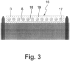
- FIG. 3 shows a belt 16 as a traction element for elevator technology, specifically as in embodiment 2 in the form of a flat belt.
- the difference is that here the first material A forms the belt core 18 and the second material B forms the belt sleeve 19 .
- the tension member 17 is embedded in the belt core 18 with the first material A being completely encased.
- the belt sleeve 19 completely surrounds the belt core 18.
- the first material A with a high proportion of a fire-retardant additive e.g. 25% by weight
- the entire belt sleeve 19, on the other hand is equipped with the second material B, which is poor (eg 3% by weight) or free of a flame retardant additive. If the belt sleeve 19 with the second material B burns through at the points exposed to fire, the belt core 18 with the first material A then prevents the fire from spreading to the entire belt 16.
Landscapes
- Engineering & Computer Science (AREA)
- General Engineering & Computer Science (AREA)
- Mechanical Engineering (AREA)
- Lift-Guide Devices, And Elevator Ropes And Cables (AREA)
Description
- Die Erfindung betrifft einen Riemen für die Antriebstechnik, bestehend wenigstens aus:
- einem Riemenkörper aus einem polymeren Material mit elastischen Eigenschaften, umfassend eine Decklage als Riemenrücken und einen Unterbau mit einer Kraftübertragungszone; sowie
- einem in dem Riemenkörper eingebetteten Zugträger in Form von Stahlcorden.
- Derartige Riemen, die auch als Antriebsriemen oder Kraftübertragungsriemen bezeichnet werden, können als Flachriemen, Keilriemen, Keilrippenriemen, Zahnriemen oder als Verbundseile ausgebildet sein. Diesbezüglich wird insbesondere auf folgende Patentliteratur verwiesen:
DE 38 23 157 A1 ,DE 100 16 351 A1 ,DE 10 2006 007 509 A1 ,DE 10 2007 062 285 A1 ,DE 10 2008 012 044 A1 ,WO 2005/080821 A1 ,WO 2006/066669 A1 ,US 3 981 206 ,US 5 417 618 ,US3545293 undUS 6 491 598 . - Die Elastizität eines Riemens wird dadurch erreicht, dass der Riemenkörper und somit die Decklage und der Unterbau aus einem polymeren Material mit elastischen Eigenschaften bestehen, wobei hier insbesondere die beiden Materialgruppen Elastomere und thermoplastische Elastomere zu nennen sind. Von besonderer Bedeutung sind Elastomere auf der Basis einer vulkanisierten Kautschukmischung, enthaltend wenigstens eine Kautschukkomponente und Mischungsingredienzien. Als Kautschukkomponente wird insbesondere Ethylen-Propylen-Kautschuk (EPM), Ethylen-Propylen-Dien-Kautschuk (EPDM), (teil)hydrierter Nitrilkautschuk (HNBR), Fluor-Kautschuk (FKM), Naturkautschuk (NR), Chloropren-Kautschuk (CR), Styrol-Butadien-Kautschuk (SBR), Butadien-Kautschuk (BR) oder Polyurethan (PU) eingesetzt, die unverschnitten oder mit wenigstens einer weiteren Kautschukkomponente, insbesondere mit einem der vorgenannten Kautschuktypen, verschnitten sind, beispielsweise in Form eines EPM/EPDM- oder SBR/BR-Verschnittes. Von besonderer Bedeutung ist dabei HNBR, EPM, EPDM, PU oder ein EPM/EPDM-Verschnitt. Die Mischungsingredienzien umfassen wenigstens einen Vernetzer oder ein Vernetzersystem (Vernetzungsmittel und Beschleuniger). Weitere Mischungsingredienzien sind zumeist noch ein Füllstoff und/oder ein Verarbeitungshilfsmittel und/oder ein Weichmacher und/oder ein Alterungsschutzmittel sowie gegebenenfalls weitere Zusatzstoffe, beispielsweise Fasern zwecks Verstärkung, und Farbpigmente. Diesbezüglich wird auf den allgemeinen Stand der Kautschukmischungstechnologie verwiesen.
- Der Riemen ist mit einem eingebetteten Zugträger versehen, der aus wenigstens einem in Riemenlängsrichtung verlaufenden Zugstrang gebildet ist. Zumeist bilden mehrere Zugstränge eine Zugträgerlage. Von besonderer Bedeutung ist dabei ein Zugstrang in Cordconstruktion, wobei es diesbezüglich nach dem Stand der Technik verschiedene Werkstoffkonzeptionen gibt. Die wesentlichen Werkstofftypen sind: Stahl, Polyamid (PA), Aramid, Polyester, Glasfasern, Kohlefasern, Basalt, Polyetheretherketon (PEEK), Polyethylentherephthalat (PET), Polybenzoxazol (PBO) oder Polyethylen-2,6-naphthalat (PEN). Der Zugstrang ist zudem zumeist mit einem Haftsystem, beispielsweise mit einem Resorcin-Formaldeyd-Latex (RFL), präpariert, so dass eine dauerwirksame Haftung zu dem umgebenden polymeren Material gewährleistet ist.
- Bei endlos geschlossenen Riemen für den Fahrzeugbau spielt der Werkstoff Stahl zwischenzeitlich eine untergeordnete Rolle. Hier werden insbesondere Zugstränge aus PA, PET sowie neuerdings aus Basalt eingesetzt.
- Bei den nicht endlos geschlossenen Riemen als Zugelement in der Aufzugstechnik - im folgenden ein Schwerpunktsthema - kommt jedoch dem Zugstrangwerkstoff Stahl, insbesondere in Form von Stahlcorden, wegen der hohen Zugkraft eine wesentliche Bedeutung zu. Hinsichtlich des diesbezüglichen Standes der Technik wird insbesondere auf folgende Patentliteratur verwiesen:
DE 10 2006 020 633 B3 ,DE 10 2008 018 191 A1 ,DE 10 2008 018 192 A1 ,DE 10 2008 037 537 A1 ,DE 10 2008 037 538 A1 , -
EP 1 396 458 A2 ,EP 1 555 234 B1 ,US 2002/0000346 A1 undUS 6 739 433 . Insbesondere die Kraftübertragungszone eines Riemens wird mit einer abriebsfesten Beschichtung versehen, die zusätzlich zur Geräuschreduzierung dient und zudem noch ölbeständig ausgerüstet sein kann. Eingesetzt wird dabei eine Flockauflage, insbesondere in Form eines Baumwoll- oder Aramidflocks, eine dünne mit Fasern (z.B. Aramidfasern) gefüllte elastische Polymerschicht, eine Textilauflage, insbesondere in Form eines Gewebes, Gewirkes oder Gestrickes, oder eine Folie (z.B. PTFE-Folie) oder ein Folienverbund (z.B. PA-PTFE-Folie). Von besonderer Bedeutung ist das Gewebe. Die hier genannten Beschichtungen werden auf der Kontaktseite zum Riemenkörper, insbesondere zum dessen Unterbau, zumeist haftfreundlich präpariert, beispielsweise mit RFL. - Ein Problem bei Riemen aller Art ist, dass das polymere Material des Riemenkörpers sehr gut brennbar ist. Im Brandfall würde das gesamte Riemenkörpermaterial abbrennen und gegebenenfalls auch noch den Zugträger schädigen. Diese Problematik ist besonders relevant bei einem riemenartigen Zugelement für die Aufzugstechnik, bei dem dann der Stahlzugträger beschädigt werden kann. Auf jeden Fall wäre die Funktion und somit die Sicherheit des Aufzuges nicht mehr gegeben.
- Die Aufgabe der Erfindung besteht nun darin, einen Riemen, insbesondere ein Zugelement für die Aufzugstechnik, bereitzustellen, bei dem das Riemenkörpermaterial nicht brennbar oder selbstverlöschend sein soll, so dass im Brandfall nicht der gesamte Riemen, insbesondere das gesamte Zugelement, betroffen ist, und zwar bei einer nach wie vor vorhandenen Funktionsfähigkeit, insbesondere bei Aufzugsanlagen.
- Gelöst wird diese Aufgabe durch ein Riemen gemäß Anspruch 1.
- Die eingangs genannten Mischungsingredienzien für den polymeren Werkstoff werden insbesondere bei dem ersten Material A durch das brandhemmende Additiv erweitert. Hinsichtlich des ersten Materials A und des zweiten Material B gelten innerhalb des Riemenkörpers folgende Mengenanteile:
- erstes Material A: 40 Gew.-% bis 95 Gew.-%, insbesondere 60 Gew.-% bis 80 Gew.-%
- zweites Material B: 60 Gew.-% bis 5 Gew.-%, insbesondere 40 Gew.-% bis 20 Gew.-%
- Als brandhemmende Additive kommen folgende Substanzklassen zum Einsatz:
- Melaminphosphat, Melaminpolyphosphat
- Melamincyanurat
- Dabei kann eine einzige Substanzklasse, beispielsweise ein Melaminphospat, oder ein Zwei- oder Mehr-Komponenten-System, beispielsweise ein Gemisch aus Melaminphosphat und Melamincyanurat, verwendet werden.
- Die Additive sind dabei im Wesentlichen gleichmäßig in der Polymermatrix eingemischt, insbesondere bei dem ersten Material A.
- Der Mengenanteil an dem brandhemmenden Additiv für das erste Material A beträgt 5 Gew.-% bis 50 Gew.-%.
- Der Mengenanteil an dem brandhemmenden Additiv für das zweite Material B beträgt dagegen 0 bis 3 Gew.-%. Die brandhemmenden Eigenschaften konzentrieren sich somit ausschließlich auf das erste Material A.
- Die Decklage des Riemens, wo die hohen mechanischen Eigenschaften nicht gefordert sind, ist mit dem ersten Material A mit seiner brandhemmenden Charakteristik ausgestattet.
- Da der Unterbau mit seiner Kraftübertragungszone, die mit der Traktionsscheibe in Kontakt steht, am höchsten mechanisch beansprucht ist, kommt hier dagegen das zweite Material B mit keiner oder nur einer geringen brandhemmenden Charakteristik zum Einsatz. Vorteilhafterweise enthält das zweite Material keine brandhemmenden Additive, da die Beimischung derartiger Additive das mechanische Eigenschaftsbild des polymeren Werkstoffes nachteilig verändern kann.
- Der Bereich des Zugträgers, der auch den Übergangsbereich von Decklage und Unterbau bildet, kann mit dem ersten Material A und/oder zweiten Material B in Verbindung stehen, wobei insbesondere folgende zwei Varianten zur Anwendung gelangen:
- Das zweite Material B ist derart im Unterbau eingearbeitet, dass der Zugträger partiell oder vollständig vom zweiten Material B ummantelt ist. Die unmittelbare Umgebung des Zugträgers weist somit keine oder nur eine geringe brandhemmende Charakteristik auf. Ein derartiges Materialkonzept wird in Verbindung mit dem Ausführungsbeispiel gemäß
Fig. 1 noch näher vorgestellt. - Das zweite Material B ist derart im Unterbau eingearbeitet, dass der Zugträger vom ersten Material A partiell oder vollständig ummantelt ist. Die unmittelbare Umgebung des Zugträgers wird somit in die brandhemmende Charakteristik einbezogen. Ein derartiges Materialkonzept wird in Verbindung mit dem Ausführungsbeispiel gemäß
Fig. 2 ebenfalls noch näher vorgestellt. - Nach einer weiteren Gestaltungsmöglichkeit bildet das erste Material A den Riemenkern und das zweite Material B die Riemenhülle. Der Zugträger ist dabei insbesondere unter vollständiger Ummantelung des ersten Materials A im Riemenkern eingebettet. Die unmittelbare Umgebung des Zugträgers wird somit in die brandhemmende Charakteristik einbezogen. Die Riemenhülle mit dem zweiten Material B umgibt vorzugsweise vollständig den Riemenkern. Ein derartiges Materialkonzept wird in Verbindung mit dem Ausführungsbeispiel gemäß
Fig. 3 noch näher vorgestellt. - Zumeist ist es ausreichend, wenn der Riemenkörper ausschließlich aus den beiden Materialien A und B besteht, insbesondere in Verbindung mit den oben genannten zwei Varianten.
- Je nach Riementyp sowie der Lage des Zugträgers kann es vorteilhaft sein, den Riemenkörper zusätzlich mit einer elastischen Zwischenschicht mit einem dritten Material C auszustatten, wobei innerhalb dieser Zwischenschicht der Zugträger eingebettet ist. In diese Zwischenschicht kann ein brandhemmendes Additiv eingemischt sein, wobei auf folgendes Beispiel verwiesen wird: Decklageerstes Material A25 Gew.-%Unterbau mit Kraftübertragungszonezweites Material B-Zwischenschicht mit eingebettetem Zugträgerdrittes Material C5 Gew.-%
- Von dem Unterbau, der frei von einem brandhemmenden Additiv ist, erfährt der Riemenkörper zur Decklage hin eine steigende Konzentration an dem brandhemmenden Additiv.
- Der Riemenkörper kann zusätzlich mit wenigstens einer eingebetteten Schicht versehen sein. Diese Schicht besteht insbesondere aus einem textilen Werkstoff in Form eines Gewebes, Gewirkes oder Gestrickes. Diese Schicht kann zudem brandhemmend ausgerüstet sein, indem beispielsweise die Textilfäden brandhemmend präpariert sind.
- Ebenso können die Decklage und/oder die Kraftübertragungszone zusätzlich mit einer Beschichtung versehen sein. Als Beschichtung wird insbesondere eine Textilauflage in Form eines Gewebes, Gewirkes oder Gestrickes eingesetzt. Von besonderer Bedeutung ist dabei die Gewebeauflage. Die Beschichtung kann ebenfalls brandhemmend ausgerüstet sein, indem wiederum beispielsweise die Textilfäden brandhemmend präpariert sind.
- Der Riemen ist als Flachriemen, Keilriemen, Keilrippenriemen, Zahnriemen oder als Verbundseile ausgebildet.
- Der erfindungsgemäße Riemen wird insbesondere als Zugelement in der Aufzugstechnik verwendet, insbesondere unter Einsatz von Verbundseilen, eines Flachriemens oder Zahnriemens. Im Brandfall wird das Feuer nicht über das Zugelement über die Höhe des gesamten Aufzugsschachtes verteilt. Das so materialmäßig ausgerüstete Zugelement fängt sehr schlecht Feuer und erlischt zumeist nach sehr kurzer Brandstrecke von alleine wieder. Der Aufzug bleibt bedingt funktionstüchtig. Ein weiterer Vorteil ist, dass ein derartiges Zugelement einen Gebäudebrand nicht von einer Etage auf die nächste Etage übertragen kann.
- Die Erfindung wird nun anhand von zwei Ausführungsbeispielen unter Bezugnahme auf schematische Zeichnungen erläutert. Es zeigen:
-
Fig. 1 - einen Riemen in Form von Verbundseilen als Zugelement für die Aufzugstechnik im Zusammenwirken mit einer profilierten Traktionsscheibe;
-
Fig. 2 - einen Riemen in Form eines Flachriemens als Zugelement für die Aufzugstechnik im Zusammenwirken mit einer unprofilierten Traktionsscheibe;
-
Fig. 3 - einen Riemen in Form eines Flachriemens mit Riemenkern und Riemenhülle als Zugelement für die Aufzugstechnik im Zusammenwirken mit einer unprofilierten Traktionsscheibe.
-
Fig. 1 zeigt einen Riemen 1 als Zugelement für die Aufzugstechnik, und zwar in Form von Verbundseilen mit einer Decklage 2 als Riemenrücken, einem eingebetteten Zugträger 3 mit mehreren in Längsrichtung verlaufenden Zugsträngen in Form von Stahlcorden sowie einem Unterbau 4. Der Unterbau 4 weist eine Rippenrillenstruktur auf, gebildet aus Rippen 5 und Rillen 6. Die Stahlcorde des Zugträgers 3 sind dabei jeweils im Wesentlichen innerhalb einer Rippe 5 angeordnet. Der Unterbau 4 umfasst schließlich die Kraftübertragungszone 7, die mit einer entsprechend profilierten Traktionsscheibe 8 korrespondiert. Hinsichtlich konstruktiver Details der Traktionsscheibe 8 wird beispielsweise auf die beiden OffenlegungsschriftenDE 10 2008 037 537 A1 undDE 10 2008 037 538 A1 verwiesen. - Die Decklage 2 und der Unterbau 4 bilden als Gesamteinheit den elastischen Riemenkörper, der auch als Grundkörper bezeichnet wird, beispielsweise auf PU-Basis. Der Riemenkörper besteht dabei aus einem ersten Material A und einem zweiten Material B. Das erste Material A mit einem hohen Anteil an einem brandhemmenden Additiv (z.B. 25 Gew.-%) umfasst dabei die gesamte Decklage 2, wo die hohen mechanischen Eigenschaften nicht gefordert sind. Das zweite Material B, das arm (z.B. 3 Gew.-%) oder frei an einem brandhemmenden Additiv ist, umfasst nahezu den gesamten Unterbau 4 mit der Kraftübertragungszone 7. Dort ist der Riemenkörper am stärksten mechanisch belastet. Das zweite Material B ist dabei innerhalb einer Rippe 5 des Unterbaus 4 angeordnet und ummantelt zugleich nahezu den gesamten Zugträger 3.
-
Fig. 2 zeigt einen Riemen 9 als Zugelement für die Aufzugstechnik, und zwar hier in Form eines Flachriemens mit einer Decklage 10 als Riemenrücken, einem eingebetteten Zugträger 11 mit mehreren in Längsrichtung verlaufenden Zugsträngen in Form von Stahlcorden sowie einem Unterbau 12. Der Unterbau 12 ist hier flach ausgebildet und umfasst die Kraftübertragungszone 13, die mit einer Traktionsscheibe 14 mit Bordscheibe 15 korrespondiert. Hinsichtlich konstruktiver Details der Traktionsscheibe 14 wird hier beispielsweise auf die OffenlegungsschriftUS 2002/0000346 A1 verwiesen. - Die Decklage 10 und der Unterbau 12 bilden hier ebenfalls als Gesamteinheit den elastischen Riemenkörper, beispielsweise wiederum auf PU-Basis. Der Riemenkörper besteht dabei aus einem ersten Material A und einem zweiten Material B. Das erste Material A mit einem hohen Anteil an einem brandhemmenden Additiv (z.B. 25 Gew.-%) umfasst dabei die gesamte Decklage 10 sowie den gesamten Bereich des Zugträgers 11. Dies bedeutet, dass hier sämtliche Stahlcorde von dem ersten Material A vollständig ummantelt sind. Der Unterbau 12 mit der flachen Kraftübertragungszone 13 ist mit dem zweiten Material B ausgestattet, das arm (z.B. 3 Gew.-%) oder frei an einem brandhemmenden Additiv ist.
-
Fig. 3 zeigt einen Riemen 16 als Zugelement für die Aufzugstechnik, und zwar wie bei dem Ausführungsbeispiel 2 in Form eines Flachriemens. Der Unterschied besteht darin, dass hier das erste Material A den Riemenkern 18 und das zweite Material B die Riemenhülle 19 bildet. Der Zugträger 17 ist dabei unter vollständiger Ummantelung des ersten Materials A im Riemenkern 18 eingebettet. Die Riemenhülle 19 umgibt vollständig den Riemenkern 18. Das erste Material A mit einem hohen Anteil an einem brandhemmenden Additiv (z.B. 25 Gew.-%) umfasst somit den gesamten Riemenkern 18. Die gesamte Riemenhülle 19 ist dagegen mit dem zweiten Material B ausgestattet, das arm (z.B. 3 Gew.-%) oder frei an einem brandhemmenden Additiv ist. Brennt also die Riemenhülle 19 mit dem zweiten Material B an den einem Feuer ausgesetzten Stellen durch, so verhindert dann der Riemenkern 18 mit dem ersten Material A die Brandausdehnung auf den gesamten Riemen 16. - Hinsichtlich der Traktionsscheibe wird auf das Ausführungsbeispiel gemäß
Fig. 2 verwiesen. -
- 1 Riemen als Zugelement in Form von Verbundseilen
- 2 Decklage als Riemenrücken
- 3 Zugträger in Form von Stahlcorden
- 4 Unterbau
- 5 Rippen
- 6 Rillen
- 7 Kraftübertragungszone
- 8 Traktionsscheibe
- 9 Riemen als Zugelement in Form eines Flachriemens
- 10 Decklage als Riemenrücken
- 11 Zugträger in Form von Stahlcorden
- 12 Unterbau
- 13 Kraftübertragungszone
- 14 Traktionsscheibe
- 15 Bordscheibe
- 16 Riemen als Zugelement in Form eines Flachriemens
- 17 Zugträger in Form von Stahlcorden
- 18 Riemenkern mit eingebetteten Zugträgern
- 19 Riemenhülle
- erstes Material A
- zweites Material B
Claims (5)
- Riemen (1, 9, 16) für die Antriebstechnik, bestehend wenigstens aus:- einem Riemenkörper aus einem polymeren Material mit elastischen Eigenschaften, umfassend eine Decklage (2, 10) als Riemenrücken und einen Unterbau (4, 12) mit einer Kraftübertragungszone (7, 13); sowie- einem in dem Riemenkörper eingebetteten Zugträger in Form von Stahlcorden (3, 11, 17);dadurch gekennzeichnet, dass der Riemenkörper aus wenigstens zwei verschiedenen Materialen A und B besteht, nämlich aus:- einem ersten Material A, das mit einem brandhemmenden Additiv ausgerüstet ist und überall dort im Riemenkörper verbaut ist, wo die hohen mechanischen Eigenschaften nicht gefordert sind, wobei der Mengenanteil an dem brandhemmenden Additiv 5 bis 50 Gew.-% beträgt; sowie- einem zweiten Material B, das arm oder frei an einem brandhemmenden Additiv ist und in dem Bereich des Riemenkörpers zum Einsatz kommt, welcher am höchsten mechanisch beansprucht ist wobei der Mengenanteil an dem brandhemmenden Additiv 0 bis 3 Gew.-% beträgt, und- wobei das brandhemmende Additiv im Wesentlichen gleichmäßig in der Polymermatrix eingemischt ist und wobei als brandhemmende Additiv Melaminphosphat und/oder Melaminpolyphosphat und/oder Melamincyanurat zum Einsatz gelangt und- wobei hinsichtlich des ersten Materials A und des zweiten Materials B folgende Mengenanteile gelten:o erstes Material A: 40 Gew.-% bis 95 Gew.-%o zweites Material B: 60 Gew.-% bis 5 Gew.-% und entweder- wobei die Decklage (2, 10) des Riemens (1, 9) mit dem ersten Material A ausgestattet ist und- wobei der Unterbau (4, 12) des Riemens (1, 9) mit der Kraftübertragungszone (7, 13) mit dem zweiten Material B ausgestattet ist
oder- wobei das erste Material A den Riemenkern (18) und das zweite Material B die Riemenhülle (19) bildet. - Riemen nach Anspruch 1, dadurch gekennzeichnet, dass der Riemenkörper zusätzlich mit wenigstens einer eingebetteten Schicht versehen ist.
- Riemen nach einem der Ansprüche 1 bis 2, dadurch gekennzeichnet, dass die Decklage (2, 10) und/oder die Kraftübertragungszone (7, 13) zusätzlich mit einer Beschichtung versehen ist/sind.
- Riemen nach einem der Ansprüche 1 bis 3, dadurch gekennzeichnet, dass der Riemen (1, 9) als Flachriemen (9, 16), Keilriemen, Keilrippenriemen, Zahnriemen oder als Verbundseile (1) ausgebildet ist.
- Verwendung eines Riemens (1, 9, 16) nach einem der Ansprüche 1 bis 4 als riemenartiges Zugelement für die Aufzugstechnik.
Applications Claiming Priority (2)
| Application Number | Priority Date | Filing Date | Title |
|---|---|---|---|
| DE102010016872A DE102010016872A1 (de) | 2010-05-11 | 2010-05-11 | Riemen für die Antriebstechnik, insbesondere riemenartiges Zugelement für die Aufzugstechnik, mit brandhemmenden Eigenschaften |
| PCT/EP2010/063776 WO2011141068A1 (de) | 2010-05-11 | 2010-09-20 | Riemen für die antriebstechnik, insbesondere riemenartiges zugelement für die aufzugstechnik, mit brandhemmenden eigenschaften |
Publications (3)
| Publication Number | Publication Date |
|---|---|
| EP2569242A1 EP2569242A1 (de) | 2013-03-20 |
| EP2569242B1 EP2569242B1 (de) | 2019-09-04 |
| EP2569242B2 true EP2569242B2 (de) | 2023-03-01 |
Family
ID=43428840
Family Applications (1)
| Application Number | Title | Priority Date | Filing Date |
|---|---|---|---|
| EP10755164.0A Active EP2569242B2 (de) | 2010-05-11 | 2010-09-20 | Riemen für die antriebstechnik, insbesondere riemenartiges zugelement für die aufzugstechnik, mit brandhemmenden eigenschaften |
Country Status (4)
| Country | Link |
|---|---|
| US (1) | US20120329591A1 (de) |
| EP (1) | EP2569242B2 (de) |
| DE (1) | DE102010016872A1 (de) |
| WO (1) | WO2011141068A1 (de) |
Families Citing this family (31)
| Publication number | Priority date | Publication date | Assignee | Title |
|---|---|---|---|---|
| US8052820B2 (en) * | 2005-09-13 | 2011-11-08 | Otis Elevator Company | Method of making a load bearing member for an elevator system |
| DE102007021434B4 (de) * | 2007-05-08 | 2018-10-18 | Contitech Antriebssysteme Gmbh | Aufzugsanlagenzugmittel |
| BR112015000948B1 (pt) * | 2012-07-18 | 2020-12-22 | Otis Elevator Company | fita, e, método para a fabricação de uma fita |
| DE102012110769A1 (de) | 2012-11-09 | 2014-05-15 | Contitech Antriebssysteme Gmbh | Riemen für die Antriebstechnik, insbesondere riemenartiges Zugelement für die Aufzugstechnik, mit brandhemmenden Eigenschaften |
| EP2749519B1 (de) | 2012-12-27 | 2020-07-22 | KONE Corporation | Aufzug mit einer riemenartigen Seile umfassend nichtmetallischen Fasern. |
| CN110654958B (zh) * | 2014-03-06 | 2021-03-23 | 奥的斯电梯公司 | 纤维增强的电梯带及制造方法 |
| DE102014217309A1 (de) | 2014-08-29 | 2016-03-03 | Contitech Antriebssysteme Gmbh | Riemen für die Antriebstechnik, insbesondere riemenartiges Zugelement für die Aufzugstechnik, mit brandhemmenden Eigenschaften |
| US9873593B2 (en) * | 2015-05-07 | 2018-01-23 | Otis Elevator Company | Fire resistant coated steel belt |
| CN105173973A (zh) * | 2015-07-27 | 2015-12-23 | 苏州台菱电梯有限公司 | 一种带有智能钢带的消防救援电梯 |
| CN105752809A (zh) * | 2016-03-29 | 2016-07-13 | 江南嘉捷电梯股份有限公司 | 一种曳引悬挂电梯 |
| US10336579B2 (en) | 2016-03-29 | 2019-07-02 | Otis Elevator Company | Metal coating of load bearing member for elevator system |
| US10029887B2 (en) | 2016-03-29 | 2018-07-24 | Otis Elevator Company | Electroless metal coating of load bearing member for elevator system |
| EP3243785B1 (de) * | 2016-05-11 | 2021-04-07 | KONE Corporation | Seil, aufzugsanordnung und aufzug |
| DE102016215730A1 (de) * | 2016-08-23 | 2018-03-01 | Contitech Antriebssysteme Gmbh | Verfahren zur mehrstufigen Herstellung eines Zug- oder Tragmittels |
| US10974929B2 (en) * | 2016-11-07 | 2021-04-13 | Otis Elevator Company | Load bearing member for an elevator system having an elastomer and phosphonate blended bonding agent |
| US10472210B2 (en) * | 2016-11-07 | 2019-11-12 | Otis Elevator Company | Load bearing member for an elevator system having a metalized polymer coating |
| KR102518963B1 (ko) | 2016-12-12 | 2023-04-07 | 오티스 엘리베이터 컴파니 | 엘리베이터 시스템용 하이브리드 직물-라미네이트된 벨트 |
| KR102558412B1 (ko) * | 2017-04-03 | 2023-07-24 | 오티스 엘리베이터 컴파니 | 추가적인 층을 갖는 엘리베이터 벨트 |
| KR102623964B1 (ko) * | 2017-04-20 | 2024-01-11 | 오티스 엘리베이터 컴파니 | 직물 인장 부재를 구비한 엘리베이터 시스템 벨트 |
| EP3392184B1 (de) | 2017-04-20 | 2020-07-01 | Otis Elevator Company | Hybridfaserzugelement für einen aufzugsystemriemen |
| AU2018202655B2 (en) | 2017-04-20 | 2023-12-07 | Otis Elevator Company | Tension member for elevator system belt |
| US10689516B2 (en) | 2017-04-20 | 2020-06-23 | Otis Elevator Company | Polymer jacket material blends with improved flame resistance |
| US11293518B2 (en) * | 2017-04-24 | 2022-04-05 | Mitsuboshi Belting Ltd. | Toothed belt |
| US20190062114A1 (en) * | 2017-08-25 | 2019-02-28 | Otis Elevator Company | Self-extinguishing load bearing member for elevator system |
| US10549952B2 (en) * | 2017-08-25 | 2020-02-04 | Otis Elevator Company | Self-extinguishing fabric belt for elevator system |
| US11274017B2 (en) * | 2017-08-25 | 2022-03-15 | Otis Elevator Company | Belt with self-extinguishing layer and method of making |
| EP3483109B1 (de) * | 2017-11-10 | 2021-01-20 | Otis Elevator Company | Riemen für ein aufzugssystem |
| DE102018219915A1 (de) * | 2018-11-21 | 2020-05-28 | Contitech Antriebssysteme Gmbh | Zug- oder Tragriemen |
| US20210024328A1 (en) * | 2019-07-22 | 2021-01-28 | Otis Elevator Company | Elevator load bearing member having a jacket including a fluoropolymer |
| DE102022210531A1 (de) | 2022-10-05 | 2024-04-11 | Contitech Antriebssysteme Gmbh | Brandhemmendes aufzugstragmittel mit antistatischen eigenschaften |
| WO2025040771A1 (en) | 2023-08-24 | 2025-02-27 | Basf Se | Load bearing belt made from flame retardant thermoplastic polyurethane (tpu) |
Family Cites Families (35)
| Publication number | Priority date | Publication date | Assignee | Title |
|---|---|---|---|---|
| US3545293A (en) | 1968-12-27 | 1970-12-08 | Owens Corning Fiberglass Corp | Industrial belt construction |
| US3981206A (en) | 1975-08-20 | 1976-09-21 | Dayco Corporation | Endless power transmission belt |
| JPS62259912A (ja) | 1986-04-30 | 1987-11-12 | Tokai Rubber Ind Ltd | コンベヤベルト |
| EP0309605A1 (de) | 1987-10-01 | 1989-04-05 | OLBO Textilwerke GmbH | Förderband |
| DE3823157A1 (de) | 1988-07-08 | 1990-02-08 | Inst Textil & Faserforschung | Verfahren zur herstellung eines beflockten flaechengebildes mit hilfe energiereicher strahlen, ausgehend von niedermolekularen polymerisierbaren verbindungen |
| JP2514568B2 (ja) | 1993-04-19 | 1996-07-10 | 三ツ星ベルト株式会社 | 歯付ベルト |
| US5881843A (en) | 1996-10-15 | 1999-03-16 | Otis Elevator Company | Synthetic non-metallic rope for an elevator |
| US6401871B2 (en) | 1998-02-26 | 2002-06-11 | Otis Elevator Company | Tension member for an elevator |
| DE29924774U1 (de) | 1998-12-22 | 2005-07-07 | Otis Elevator Co., Farmington | Aufzugsystem |
| PT2284111E (pt) | 1998-12-22 | 2013-07-19 | Otis Elevator Co | Elemento de tensão para um elevador |
| DE10016351C2 (de) | 2000-04-03 | 2002-09-26 | Contitech Antriebssysteme Gmbh | Treibriemen |
| US6491598B1 (en) | 2000-10-09 | 2002-12-10 | The Goodyear Tire & Rubber Company | Power transmission belt |
| DE10240988B4 (de) | 2002-09-05 | 2014-02-27 | Inventio Ag | Aufzugsanlage mit einer aus Riemen und Scheiben bestehenden Antriebsübertragungsanordnung |
| DK1555234T3 (da) | 2004-01-06 | 2006-08-21 | Inventio Ag | Elevator |
| EP1735543B1 (de) | 2004-02-23 | 2008-04-09 | DAYCO EUROPE S.r.l. | Zahnriemen |
| JP2006070087A (ja) | 2004-08-31 | 2006-03-16 | Tosoh Corp | 難燃性芳香族アミドブロック共重合体樹脂組成物及びそれよりなる成形体 |
| DE102004062760A1 (de) | 2004-12-21 | 2006-06-22 | Contitech Antriebssysteme Gmbh | Zahnriemen mit Zahnauflage aus Gewebe |
| DE102005016195A1 (de) * | 2005-04-08 | 2006-10-12 | Clariant Produkte (Deutschland) Gmbh | Stabilisiertes Flammschutzmittel |
| WO2007050069A1 (en) | 2005-10-27 | 2007-05-03 | Otis Elevator Company | Elevator load bearing assembly having a jacket with multiple polymer compositions |
| DE102006007509B4 (de) | 2006-02-16 | 2009-01-22 | Contitech Antriebssysteme Gmbh | Keilrippenriemen mit verbessertem Geräuschverhalten |
| DE102006020633B3 (de) | 2006-05-04 | 2007-11-29 | Contitech Antriebssysteme Gmbh | Flachriemen |
| US7939175B2 (en) | 2007-04-25 | 2011-05-10 | Veyance Technologies, Inc. | Non-halogenated rubber compounds for use in conveyor belts |
| JP2009127034A (ja) | 2007-11-28 | 2009-06-11 | Ube Ind Ltd | 難燃性ベルト用ゴム組成物および難燃性ベルト |
| DE102007062285A1 (de) | 2007-12-21 | 2009-06-25 | Contitech Antriebssysteme Gmbh | Zahnriemen |
| DE102008012044A1 (de) | 2008-03-01 | 2009-09-03 | Contitech Antriebssysteme Gmbh | Elastischer Artikel, insbesondere Antriebsriemen, mit einer Folienschutzschicht und Verfahren zu seiner Herstellung |
| US7909719B2 (en) * | 2008-03-14 | 2011-03-22 | Forbo Siegling, Llc | Belt |
| DE102008018191A1 (de) | 2008-04-10 | 2009-10-15 | Contitech Antriebssysteme Gmbh | Aufzugsystem sowie Kombination aus Abschlussvorrichtung und Zugelement |
| DE102008018192A1 (de) | 2008-04-10 | 2009-10-15 | Contitech Antriebssysteme Gmbh | Aufzugsystem sowie Kombination aus Abschlussvorrichtung und Zugelement |
| WO2009154789A1 (en) | 2008-06-20 | 2009-12-23 | Asyst Technologies, Inc. | Direct loading to and from a conveyor system |
| RU2500849C2 (ru) | 2008-08-15 | 2013-12-10 | Отис Элевэйтор Компани | Подъемная система и способ ее изготовления |
| EP2337891B2 (de) | 2008-08-15 | 2020-11-18 | Otis Elevator Company | Verwendung einer Zusammensetzung auf Melamin-Basis als Geometriestabilsator in einer Anordnung, die ein gestrecktes Zugglied und eine Hülle umfasst. |
| EP2337889B1 (de) | 2008-08-15 | 2013-08-14 | Otis Elevator Company | Verwendung eines Haftvermittlers in einem polymeren Mantel eines Kabels und entsprechendes Verfahren zur Herstellung eines Seilverbunds mit einem Mantel |
| DE102008037537B4 (de) | 2008-11-10 | 2020-11-05 | Contitech Antriebssysteme Gmbh | Zugmitteltrieb und Aufzugsanlage mit diesem Zugmitteltrieb |
| DE102008037538A1 (de) | 2008-11-10 | 2010-05-12 | Contitech Antriebssysteme Gmbh | Traktionssystem für eine Aufzugsanlage |
| CN201386757Y (zh) | 2009-04-23 | 2010-01-20 | 浙江三力士橡胶股份有限公司 | 一种带有阻燃效果的传动带 |
-
2010
- 2010-05-11 DE DE102010016872A patent/DE102010016872A1/de not_active Withdrawn
- 2010-09-20 EP EP10755164.0A patent/EP2569242B2/de active Active
- 2010-09-20 WO PCT/EP2010/063776 patent/WO2011141068A1/de not_active Ceased
-
2012
- 2012-09-06 US US13/605,697 patent/US20120329591A1/en not_active Abandoned
Also Published As
| Publication number | Publication date |
|---|---|
| US20120329591A1 (en) | 2012-12-27 |
| EP2569242A1 (de) | 2013-03-20 |
| DE102010016872A1 (de) | 2011-11-17 |
| EP2569242B1 (de) | 2019-09-04 |
| WO2011141068A1 (de) | 2011-11-17 |
Similar Documents
| Publication | Publication Date | Title |
|---|---|---|
| EP2569242B2 (de) | Riemen für die antriebstechnik, insbesondere riemenartiges zugelement für die aufzugstechnik, mit brandhemmenden eigenschaften | |
| EP2917606B1 (de) | Riemen für die antriebstechnik, insbesondere riemenartiges zugelement für die aufzugstechnik, mit brandhemmenden eigenschaften | |
| EP3186530B1 (de) | Riemen für die antriebstechnik, insbesondere riemenartiges zugelement für die aufzugstechnik, mit brandhemmenden eigenschaften | |
| EP2773500B1 (de) | Riemen mit einem zugträger, insbesondere carbon-zugträger, der mit einem vernetzten polyurethan präpariert ist, sowie präparationsverfahren | |
| DE102007042917B4 (de) | Biegeelastischer Antriebsriemen, oder Keilrippenriemen, mit einer Textilauflage auf seiner verschleißanfälligen Arbeitsseite | |
| DE102010016393A1 (de) | PAK-freier Antriebsriemen, insbesondere Zahnriemen | |
| DE102008055497A1 (de) | Elastischer Artikel, insbesondere Antriebsriemen, mit einer Textilauflage und einem Haftvermittler aus schmelzbarem Kunststoff | |
| EP2545296B1 (de) | Antriebsriemen, insbesondere keilrippenriemen, mit einer gewebeauflage | |
| EP2313257A1 (de) | Ölbeständiger antriebsriemen, insbesondere zahnriemen | |
| EP2306045B1 (de) | Antriebsriemen, insbesondere Zahnriemen, mit Basaltzugstrang | |
| EP2773808B1 (de) | Verfahren zur präparation eines zugträgers, insbesondere carbon-zugträgers, bei der fertigung eines riemens | |
| EP2549143B1 (de) | Kraftübertragungsriemen, insbesondere Keilrippenriemen | |
| DE102007044436A1 (de) | Endloser elastischer Antriebsriemen, insbesondere Keilriemen oder Keilrippenriemen, mit vermindertem Spannungsverlust | |
| DE102010060216A1 (de) | Antriebsriemen, insbesondere Keilrippenriemen, und Verfahren zu dessen Herstellung | |
| DE102008055530A1 (de) | Zahnriemen zum Antrieb einer Nockenwelle in Hochleistungsmotoren | |
| EP2844890B1 (de) | Antriebsriemen mit verbesserter textilhaftung | |
| DE102008037415A1 (de) | Antriebsriemen, insbesondere Keilrippenriemen, mit einer Textilauflage und Verfahren zu dessen Herstellung | |
| EP2538110B1 (de) | Kraftübertragungsriemen, insbesondere Zahnriemen | |
| DE102022210531A1 (de) | Brandhemmendes aufzugstragmittel mit antistatischen eigenschaften | |
| EP4351870A1 (de) | Elastomerartikel auf basis einer epdm mischung mit verbesserter hafteigenschaft und verbesserter lebensdauer | |
| DE102015224057A1 (de) | Antriebsriemen | |
| DE102009044079A1 (de) | Elastischer Antriebsriemen in Form eines Keilriemens oder eines Keilrippenriemens mit einem vergrößerten Flankenwinkel |
Legal Events
| Date | Code | Title | Description |
|---|---|---|---|
| PUAI | Public reference made under article 153(3) epc to a published international application that has entered the european phase |
Free format text: ORIGINAL CODE: 0009012 |
|
| 17P | Request for examination filed |
Effective date: 20121211 |
|
| AK | Designated contracting states |
Kind code of ref document: A1 Designated state(s): AL AT BE BG CH CY CZ DE DK EE ES FI FR GB GR HR HU IE IS IT LI LT LU LV MC MK MT NL NO PL PT RO SE SI SK SM TR |
|
| DAX | Request for extension of the european patent (deleted) | ||
| 17Q | First examination report despatched |
Effective date: 20130911 |
|
| STAA | Information on the status of an ep patent application or granted ep patent |
Free format text: STATUS: EXAMINATION IS IN PROGRESS |
|
| GRAP | Despatch of communication of intention to grant a patent |
Free format text: ORIGINAL CODE: EPIDOSNIGR1 |
|
| STAA | Information on the status of an ep patent application or granted ep patent |
Free format text: STATUS: GRANT OF PATENT IS INTENDED |
|
| INTG | Intention to grant announced |
Effective date: 20190514 |
|
| GRAS | Grant fee paid |
Free format text: ORIGINAL CODE: EPIDOSNIGR3 |
|
| GRAA | (expected) grant |
Free format text: ORIGINAL CODE: 0009210 |
|
| STAA | Information on the status of an ep patent application or granted ep patent |
Free format text: STATUS: THE PATENT HAS BEEN GRANTED |
|
| AK | Designated contracting states |
Kind code of ref document: B1 Designated state(s): AL AT BE BG CH CY CZ DE DK EE ES FI FR GB GR HR HU IE IS IT LI LT LU LV MC MK MT NL NO PL PT RO SE SI SK SM TR |
|
| REG | Reference to a national code |
Ref country code: GB Ref legal event code: FG4D Free format text: NOT ENGLISH |
|
| REG | Reference to a national code |
Ref country code: CH Ref legal event code: EP |
|
| REG | Reference to a national code |
Ref country code: AT Ref legal event code: REF Ref document number: 1175048 Country of ref document: AT Kind code of ref document: T Effective date: 20190915 |
|
| REG | Reference to a national code |
Ref country code: DE Ref legal event code: R096 Ref document number: 502010016235 Country of ref document: DE |
|
| REG | Reference to a national code |
Ref country code: IE Ref legal event code: FG4D Free format text: LANGUAGE OF EP DOCUMENT: GERMAN |
|
| REG | Reference to a national code |
Ref country code: NL Ref legal event code: MP Effective date: 20190904 |
|
| REG | Reference to a national code |
Ref country code: LT Ref legal event code: MG4D |
|
| PG25 | Lapsed in a contracting state [announced via postgrant information from national office to epo] |
Ref country code: NO Free format text: LAPSE BECAUSE OF FAILURE TO SUBMIT A TRANSLATION OF THE DESCRIPTION OR TO PAY THE FEE WITHIN THE PRESCRIBED TIME-LIMIT Effective date: 20191204 Ref country code: LT Free format text: LAPSE BECAUSE OF FAILURE TO SUBMIT A TRANSLATION OF THE DESCRIPTION OR TO PAY THE FEE WITHIN THE PRESCRIBED TIME-LIMIT Effective date: 20190904 Ref country code: FI Free format text: LAPSE BECAUSE OF FAILURE TO SUBMIT A TRANSLATION OF THE DESCRIPTION OR TO PAY THE FEE WITHIN THE PRESCRIBED TIME-LIMIT Effective date: 20190904 Ref country code: SE Free format text: LAPSE BECAUSE OF FAILURE TO SUBMIT A TRANSLATION OF THE DESCRIPTION OR TO PAY THE FEE WITHIN THE PRESCRIBED TIME-LIMIT Effective date: 20190904 Ref country code: BG Free format text: LAPSE BECAUSE OF FAILURE TO SUBMIT A TRANSLATION OF THE DESCRIPTION OR TO PAY THE FEE WITHIN THE PRESCRIBED TIME-LIMIT Effective date: 20191204 Ref country code: HR Free format text: LAPSE BECAUSE OF FAILURE TO SUBMIT A TRANSLATION OF THE DESCRIPTION OR TO PAY THE FEE WITHIN THE PRESCRIBED TIME-LIMIT Effective date: 20190904 |
|
| PG25 | Lapsed in a contracting state [announced via postgrant information from national office to epo] |
Ref country code: GR Free format text: LAPSE BECAUSE OF FAILURE TO SUBMIT A TRANSLATION OF THE DESCRIPTION OR TO PAY THE FEE WITHIN THE PRESCRIBED TIME-LIMIT Effective date: 20191205 Ref country code: LV Free format text: LAPSE BECAUSE OF FAILURE TO SUBMIT A TRANSLATION OF THE DESCRIPTION OR TO PAY THE FEE WITHIN THE PRESCRIBED TIME-LIMIT Effective date: 20190904 Ref country code: AL Free format text: LAPSE BECAUSE OF FAILURE TO SUBMIT A TRANSLATION OF THE DESCRIPTION OR TO PAY THE FEE WITHIN THE PRESCRIBED TIME-LIMIT Effective date: 20190904 Ref country code: ES Free format text: LAPSE BECAUSE OF FAILURE TO SUBMIT A TRANSLATION OF THE DESCRIPTION OR TO PAY THE FEE WITHIN THE PRESCRIBED TIME-LIMIT Effective date: 20190904 |
|
| PG25 | Lapsed in a contracting state [announced via postgrant information from national office to epo] |
Ref country code: IT Free format text: LAPSE BECAUSE OF FAILURE TO SUBMIT A TRANSLATION OF THE DESCRIPTION OR TO PAY THE FEE WITHIN THE PRESCRIBED TIME-LIMIT Effective date: 20190904 Ref country code: PT Free format text: LAPSE BECAUSE OF FAILURE TO SUBMIT A TRANSLATION OF THE DESCRIPTION OR TO PAY THE FEE WITHIN THE PRESCRIBED TIME-LIMIT Effective date: 20200106 Ref country code: PL Free format text: LAPSE BECAUSE OF FAILURE TO SUBMIT A TRANSLATION OF THE DESCRIPTION OR TO PAY THE FEE WITHIN THE PRESCRIBED TIME-LIMIT Effective date: 20190904 Ref country code: NL Free format text: LAPSE BECAUSE OF FAILURE TO SUBMIT A TRANSLATION OF THE DESCRIPTION OR TO PAY THE FEE WITHIN THE PRESCRIBED TIME-LIMIT Effective date: 20190904 Ref country code: EE Free format text: LAPSE BECAUSE OF FAILURE TO SUBMIT A TRANSLATION OF THE DESCRIPTION OR TO PAY THE FEE WITHIN THE PRESCRIBED TIME-LIMIT Effective date: 20190904 Ref country code: RO Free format text: LAPSE BECAUSE OF FAILURE TO SUBMIT A TRANSLATION OF THE DESCRIPTION OR TO PAY THE FEE WITHIN THE PRESCRIBED TIME-LIMIT Effective date: 20190904 |
|
| PG25 | Lapsed in a contracting state [announced via postgrant information from national office to epo] |
Ref country code: CZ Free format text: LAPSE BECAUSE OF FAILURE TO SUBMIT A TRANSLATION OF THE DESCRIPTION OR TO PAY THE FEE WITHIN THE PRESCRIBED TIME-LIMIT Effective date: 20190904 Ref country code: SM Free format text: LAPSE BECAUSE OF FAILURE TO SUBMIT A TRANSLATION OF THE DESCRIPTION OR TO PAY THE FEE WITHIN THE PRESCRIBED TIME-LIMIT Effective date: 20190904 Ref country code: IS Free format text: LAPSE BECAUSE OF FAILURE TO SUBMIT A TRANSLATION OF THE DESCRIPTION OR TO PAY THE FEE WITHIN THE PRESCRIBED TIME-LIMIT Effective date: 20200224 Ref country code: SK Free format text: LAPSE BECAUSE OF FAILURE TO SUBMIT A TRANSLATION OF THE DESCRIPTION OR TO PAY THE FEE WITHIN THE PRESCRIBED TIME-LIMIT Effective date: 20190904 |
|
| REG | Reference to a national code |
Ref country code: DE Ref legal event code: R026 Ref document number: 502010016235 Country of ref document: DE |
|
| PLBI | Opposition filed |
Free format text: ORIGINAL CODE: 0009260 |
|
| PLAX | Notice of opposition and request to file observation + time limit sent |
Free format text: ORIGINAL CODE: EPIDOSNOBS2 |
|
| 26 | Opposition filed |
Opponent name: OTIS ELEVATOR COMPANY Effective date: 20200604 |
|
| PG2D | Information on lapse in contracting state deleted |
Ref country code: IS |
|
| PG25 | Lapsed in a contracting state [announced via postgrant information from national office to epo] |
Ref country code: DK Free format text: LAPSE BECAUSE OF FAILURE TO SUBMIT A TRANSLATION OF THE DESCRIPTION OR TO PAY THE FEE WITHIN THE PRESCRIBED TIME-LIMIT Effective date: 20190904 Ref country code: IE Free format text: LAPSE BECAUSE OF NON-PAYMENT OF DUE FEES Effective date: 20190920 Ref country code: LU Free format text: LAPSE BECAUSE OF NON-PAYMENT OF DUE FEES Effective date: 20190920 Ref country code: IS Free format text: LAPSE BECAUSE OF FAILURE TO SUBMIT A TRANSLATION OF THE DESCRIPTION OR TO PAY THE FEE WITHIN THE PRESCRIBED TIME-LIMIT Effective date: 20200105 |
|
| REG | Reference to a national code |
Ref country code: BE Ref legal event code: MM Effective date: 20190930 |
|
| PG25 | Lapsed in a contracting state [announced via postgrant information from national office to epo] |
Ref country code: SI Free format text: LAPSE BECAUSE OF FAILURE TO SUBMIT A TRANSLATION OF THE DESCRIPTION OR TO PAY THE FEE WITHIN THE PRESCRIBED TIME-LIMIT Effective date: 20190904 Ref country code: BE Free format text: LAPSE BECAUSE OF NON-PAYMENT OF DUE FEES Effective date: 20190930 Ref country code: MC Free format text: LAPSE BECAUSE OF FAILURE TO SUBMIT A TRANSLATION OF THE DESCRIPTION OR TO PAY THE FEE WITHIN THE PRESCRIBED TIME-LIMIT Effective date: 20190904 |
|
| PLAF | Information modified related to communication of a notice of opposition and request to file observations + time limit |
Free format text: ORIGINAL CODE: EPIDOSCOBS2 |
|
| REG | Reference to a national code |
Ref country code: AT Ref legal event code: MM01 Ref document number: 1175048 Country of ref document: AT Kind code of ref document: T Effective date: 20190920 |
|
| PLBB | Reply of patent proprietor to notice(s) of opposition received |
Free format text: ORIGINAL CODE: EPIDOSNOBS3 |
|
| PG25 | Lapsed in a contracting state [announced via postgrant information from national office to epo] |
Ref country code: AT Free format text: LAPSE BECAUSE OF NON-PAYMENT OF DUE FEES Effective date: 20190920 |
|
| PG25 | Lapsed in a contracting state [announced via postgrant information from national office to epo] |
Ref country code: CY Free format text: LAPSE BECAUSE OF FAILURE TO SUBMIT A TRANSLATION OF THE DESCRIPTION OR TO PAY THE FEE WITHIN THE PRESCRIBED TIME-LIMIT Effective date: 20190904 |
|
| PG25 | Lapsed in a contracting state [announced via postgrant information from national office to epo] |
Ref country code: MT Free format text: LAPSE BECAUSE OF FAILURE TO SUBMIT A TRANSLATION OF THE DESCRIPTION OR TO PAY THE FEE WITHIN THE PRESCRIBED TIME-LIMIT Effective date: 20190904 Ref country code: HU Free format text: LAPSE BECAUSE OF FAILURE TO SUBMIT A TRANSLATION OF THE DESCRIPTION OR TO PAY THE FEE WITHIN THE PRESCRIBED TIME-LIMIT; INVALID AB INITIO Effective date: 20100920 |
|
| PLBP | Opposition withdrawn |
Free format text: ORIGINAL CODE: 0009264 |
|
| PG25 | Lapsed in a contracting state [announced via postgrant information from national office to epo] |
Ref country code: TR Free format text: LAPSE BECAUSE OF FAILURE TO SUBMIT A TRANSLATION OF THE DESCRIPTION OR TO PAY THE FEE WITHIN THE PRESCRIBED TIME-LIMIT Effective date: 20190904 |
|
| PG25 | Lapsed in a contracting state [announced via postgrant information from national office to epo] |
Ref country code: MK Free format text: LAPSE BECAUSE OF FAILURE TO SUBMIT A TRANSLATION OF THE DESCRIPTION OR TO PAY THE FEE WITHIN THE PRESCRIBED TIME-LIMIT Effective date: 20190904 |
|
| PUAH | Patent maintained in amended form |
Free format text: ORIGINAL CODE: 0009272 |
|
| STAA | Information on the status of an ep patent application or granted ep patent |
Free format text: STATUS: PATENT MAINTAINED AS AMENDED |
|
| 27A | Patent maintained in amended form |
Effective date: 20230301 |
|
| AK | Designated contracting states |
Kind code of ref document: B2 Designated state(s): AL AT BE BG CH CY CZ DE DK EE ES FI FR GB GR HR HU IE IS IT LI LT LU LV MC MK MT NL NO PL PT RO SE SI SK SM TR |
|
| REG | Reference to a national code |
Ref country code: DE Ref legal event code: R102 Ref document number: 502010016235 Country of ref document: DE |
|
| P01 | Opt-out of the competence of the unified patent court (upc) registered |
Effective date: 20230602 |
|
| REG | Reference to a national code |
Ref country code: CH Ref legal event code: U11 Free format text: ST27 STATUS EVENT CODE: U-0-0-U10-U11 (AS PROVIDED BY THE NATIONAL OFFICE) Effective date: 20251001 |
|
| PGFP | Annual fee paid to national office [announced via postgrant information from national office to epo] |
Ref country code: DE Payment date: 20250930 Year of fee payment: 16 |
|
| PGFP | Annual fee paid to national office [announced via postgrant information from national office to epo] |
Ref country code: GB Payment date: 20250918 Year of fee payment: 16 |
|
| PGFP | Annual fee paid to national office [announced via postgrant information from national office to epo] |
Ref country code: FR Payment date: 20250922 Year of fee payment: 16 |
|
| PGFP | Annual fee paid to national office [announced via postgrant information from national office to epo] |
Ref country code: CH Payment date: 20251001 Year of fee payment: 16 |
|
| REG | Reference to a national code |
Ref country code: DE Ref legal event code: R081 Ref document number: 502010016235 Country of ref document: DE Owner name: CONTITECH DEUTSCHLAND GMBH, DE Free format text: FORMER OWNER: CONTITECH ANTRIEBSSYSTEME GMBH, 30165 HANNOVER, DE |