EP2570039A2 - Composant pour un dispositif d'acheminement conçu pour le transport d'articles de l'industrie de traitement du tabac ainsi que dispositif d'acheminement doté d'un tel composant - Google Patents
Composant pour un dispositif d'acheminement conçu pour le transport d'articles de l'industrie de traitement du tabac ainsi que dispositif d'acheminement doté d'un tel composant Download PDFInfo
- Publication number
- EP2570039A2 EP2570039A2 EP12183892A EP12183892A EP2570039A2 EP 2570039 A2 EP2570039 A2 EP 2570039A2 EP 12183892 A EP12183892 A EP 12183892A EP 12183892 A EP12183892 A EP 12183892A EP 2570039 A2 EP2570039 A2 EP 2570039A2
- Authority
- EP
- European Patent Office
- Prior art keywords
- component according
- opening
- articles
- conveying element
- recess
- Prior art date
- Legal status (The legal status is an assumption and is not a legal conclusion. Google has not performed a legal analysis and makes no representation as to the accuracy of the status listed.)
- Granted
Links
- 241000208125 Nicotiana Species 0.000 title claims description 22
- 235000002637 Nicotiana tabacum Nutrition 0.000 title claims description 22
- 238000012545 processing Methods 0.000 title claims description 22
- 239000012530 fluid Substances 0.000 claims abstract description 23
- 239000002184 metal Substances 0.000 claims abstract description 4
- 238000004891 communication Methods 0.000 claims description 20
- 239000011888 foil Substances 0.000 claims description 3
- 230000032258 transport Effects 0.000 description 17
- 230000008901 benefit Effects 0.000 description 7
- 230000015572 biosynthetic process Effects 0.000 description 4
- 238000013461 design Methods 0.000 description 4
- 238000012546 transfer Methods 0.000 description 4
- 230000006978 adaptation Effects 0.000 description 3
- 235000019504 cigarettes Nutrition 0.000 description 3
- 238000006073 displacement reaction Methods 0.000 description 3
- 238000003801 milling Methods 0.000 description 3
- 230000008859 change Effects 0.000 description 2
- 238000011161 development Methods 0.000 description 2
- 230000018109 developmental process Effects 0.000 description 2
- 238000012423 maintenance Methods 0.000 description 2
- 238000004519 manufacturing process Methods 0.000 description 2
- 239000000463 material Substances 0.000 description 2
- 238000000034 method Methods 0.000 description 2
- 230000008569 process Effects 0.000 description 2
- 230000008439 repair process Effects 0.000 description 2
- 238000011144 upstream manufacturing Methods 0.000 description 2
- 240000006240 Linum usitatissimum Species 0.000 description 1
- 244000061176 Nicotiana tabacum Species 0.000 description 1
- 230000009471 action Effects 0.000 description 1
- 238000007664 blowing Methods 0.000 description 1
- 238000005266 casting Methods 0.000 description 1
- 238000006243 chemical reaction Methods 0.000 description 1
- 230000001419 dependent effect Effects 0.000 description 1
- 230000000694 effects Effects 0.000 description 1
- 239000000696 magnetic material Substances 0.000 description 1
- 238000009417 prefabrication Methods 0.000 description 1
- 230000009467 reduction Effects 0.000 description 1
- 230000007480 spreading Effects 0.000 description 1
- 238000003892 spreading Methods 0.000 description 1
- 230000003313 weakening effect Effects 0.000 description 1
Images


Classifications
-
- A—HUMAN NECESSITIES
- A24—TOBACCO; CIGARS; CIGARETTES; SIMULATED SMOKING DEVICES; SMOKERS' REQUISITES
- A24C—MACHINES FOR MAKING CIGARS OR CIGARETTES
- A24C5/00—Making cigarettes; Making tipping materials for, or attaching filters or mouthpieces to, cigars or cigarettes
- A24C5/32—Separating, ordering, counting or examining cigarettes; Regulating the feeding of tobacco according to rod or cigarette condition
- A24C5/322—Transporting cigarettes during manufacturing
- A24C5/327—Construction details of the cigarette transport drum
Definitions
- the invention relates to a component for a conveying device for conveying articles of the tobacco processing industry, comprising a stationary body having a surface in which at least one vacuumable first recess is formed, and an adjacent to the surface of the body having an inner side and opposite to the surface of the body in a direction of movement movable conveying member which is provided on its outside with a plurality of successively in the direction of receiving portions for temporarily receiving the articles and first passages containing the receiving portions on the outside with at least one in fluid communication with the first recess in connects the surface of the body engageable first opening on the inside of the conveying element. Furthermore, the invention relates to a component set with at least two such components. Finally, the invention relates to a conveying device for conveying articles of the tobacco-processing industry with at least one such component.
- rod-shaped objects such as tobacco rods and sticks with limited length, filter rods or cigarettes with and without filters or cigarillos or tipping paper leaflets u.
- filter rods or cigarettes with and without filters or cigarillos or tipping paper leaflets u.
- cigarillos or tipping paper leaflets u.
- the transport of the articles of the tobacco-processing industry takes place by means of the conveying element, which moves in the direction of movement and thus in the conveying or transporting direction.
- the articles are received by the receiving sections lying one behind the other in the direction of movement on the outside of the movable conveying element.
- the receiving sections are connected via first passages formed in the movable conveying element, at least one first opening communicating with the first passages and formed on the inside of the conveying element, and the first recess in fluid communication with the first opening in the surface of the body being connected to a vacuum source in that the articles to be conveyed are sucked by a vacuum formed in the receiving sections to the outside of the movable conveying element and are taken along by the conveying element during its movement, wherein the receiving sections are in particular groove-shaped.
- the conveying device of the aforementioned type is designed as a rotary conveying device in which the stationary body substantially a rotary body and the surface of the stationary body forms an outer or circumferential surface of the rotary body and is provided as a movable conveying element, a stationary body enclosing drum disposed substantially concentric with and rotatable relative to the stationary body to convey the articles of the tobacco processing industry in a rotational direction.
- Such conveying devices and in particular rotary conveying devices are used in drum machines of the tobacco processing industry, in particular in filter attachment machines and Multifilterherstellmaschinen.
- Conveying devices and in particular rotary conveyor devices for conveying articles of the tobacco processing industry are known.
- the WO 2010/012 420 A1 a conveyor drum with receptacles for articles of the tobacco processing industry, in which various types of recordings are provided.
- the corresponding formatrelevanten components of a machine used for this purpose in particular the conveyors of the type mentioned to adapt to a modified format, which often with high effort and long downtime and the resulting high costs.
- control flange body made of cast material and in the surface forming the surface of the molded control flange often referred to as “control groove” first recess made by milling.
- control groove first recess made by milling.
- a component for a conveying device for conveying articles of the tobacco processing industry formed conveyor device having a stationary body with a surface in which at least one can be acted upon with negative pressure first recess, and adjacent to the surface of the body with an inside arranged and movable relative to the surface of the body in a direction of movement conveying element, which is provided on its outside with a plurality of moving parts in succession receiving portions for temporarily receiving the articles and first passages containing the receiving portions on the outside with at least one in fluid communication with the first Recess in the surface of the body connectable first opening on the inside of the conveying element connects, characterized by a layer which is designed for stationary arrangement on the surface of the body and with at least one provided on the surface of the body in fluid communication with the first recess in the surface of the body and with the first opening on the inside of the conveying element 6 can be brought first through opening.
- a layer on the surface or surface of the stationary body and thus between this surface of the stationary body and the inside of the conveying element is arranged.
- the arrangement of the layer according to the invention on the surface of the body is stationary, so that the position relative to the body rests stationary on the surface thereof.
- the conveying element moves not only relative to the surface of the stationary body, but in the same way with respect to the stationarily arranged according to the invention on the surface of the body layer.
- a layer is a flat, in particular web, sheet or plate-shaped, preferably flexible, element to be understood, which is preferably relatively thin and thus consumes little space, so that the use of the inventive layer, the design of the conveyor is substantially unaffected ,
- the layer Due to the arrangement on the surface of the stationary body and thus between this and the inside of the conveying element, the layer lies with its first passage opening in a flow path of the suction air, which of the receiving portions on the outside of the conveying element via the first passages formed therein and the associated first Opening on the inside of the conveying element leads to the first recess in the surface of the stationary body.
- the first through hole is capable of being formed so that it stands in a stationary arrangement on the surface of the body in fluid communication both with the recess in the surface of the body and with the first opening on the inside of the conveying element.
- the passage opening in the position is to be dimensioned accordingly.
- the passage opening can be produced inexpensively as a narrow slot for lowest air consumption.
- the air flow is determined by the appropriate dimensioning of the passage opening in the position, a standardization and a high degree of prefabrication of the stationary body can be achieved, in particular by the (s) recess (s) formed in its surface is (are) dimensioned in that such a body is suitable for the arrangement of different layers with differently dimensioned passage openings for the transport of differently dimensioned articles.
- the invention provides a simple and inexpensive way to adapt the associated conveyor to a changed format and in particular a changed length of the article to be conveyed. For an individually adapted to the format of a particular item location can be produced inexpensively, and the conversion effort is relatively low, since only the slight position instead of the heavy body is to be exchanged.
- the invention In addition to an exchange of the inventive situation to another format of articles to be conveyed, the invention also enables easier maintenance and repair.
- the replacement of only the situation according to the invention instead of the entire conveyor allows a faster performance of a format change or maintenance or repair and thus leads to lower downtime and on the other hand, as already mentioned, to a reduction in costs, since the situation requires a significantly lower material usage than the other components of the conveyor.
- a conveying device provided with the component according to the invention can also interact with other components of a machine of the tobacco-processing industry like conventional conveying devices. Therefore, it is possible to replace in conventional machines of the tobacco processing industry conventional conveyors against conveyors with the component according to the invention or retrofit only with the component according to the invention and in this way to be able to use the advantages of the invention in already existing machines of the tobacco-processing industry.
- the passage opening or passage openings in the position according to the invention can be designed, for example, as holes arranged as a row or as a hole pattern or as elongated holes in the position, wherein boreholes or elongated holes arranged in series are preferably arranged approximately in the direction of movement of the movable conveying element.
- the design and arrangement of the passage opening (s) should be able to be adapted to the format of the respectively conveyed articles and to possibly different requirements in the individual zones or regions along the conveying path.
- the component according to the invention may be provided for a conveying device designed for conveying articles of the tobacco industry, in which at least one second section, which can be acted upon by negative pressure and spaced from the first recess, is provided in the surface of the stationary body Recess and on the inside of the movable conveyor element at least one can be brought in fluid communication with the second recess in the surface of the body second opening and the movable conveyor element includes second passages connecting the receiving portions on the outside with the at least one second opening on the inside wherein, in addition to the first through-opening already mentioned, the layer has at least one second through-opening spaced from the first through-opening and arranged on the surface of the body in fluid communication with the second recess in the surface of the body and the second opening on the inside of the conveying element having.
- This embodiment is particularly advantageous in order to act on the articles to be conveyed for a particularly secure adhesion or fixation in the receiving sections on the conveyor element in each case at both end portions with suction pressure accordingly.
- the passage opening in the position at least one slot-shaped portion which preferably extends substantially in the direction of movement of the movable conveying element.
- the position according to the invention is particularly suitable for the economical production of particularly narrow slits for the lowest air consumption. Since the air flow can be particularly selectively influenced by such a configuration, such slots can also be referred to as a control groove.
- two each leading to the receiving sections passages in the conveying element extends in the position of at least one slot-shaped portion of the first passage opening substantially parallel to the at least one slot-shaped portion of the second passage opening.
- the passage opening in the position at least a first portion and a second portion, of which the first portion, viewed in the direction of movement of the movable conveying element, in front of the second portion and has a larger opening cross-section than the second portion.
- the forms front first portion has a zone for receiving the articles and therefore has a relatively large opening cross-section to produce sufficient suction force to suck for receiving the articles.
- The, viewed in the direction of movement of the movable conveying element, behind the second section forms the so-called transport zone and preferably has a particularly narrow slit or very narrow slits, since in the transport zone located on or in the receiving sections articles must be kept against unintentional loosening and therefore only a small suction force is needed, so that in the transport zone, the air consumption can be reduced to a minimum.
- the width of the second slot-shaped portion may preferably be about 0.2 mm to 2 mm.
- the component according to the invention may be provided for a conveying device designed to convey articles of the tobacco industry, in which at least one third recess actable upon overpressure is formed in the surface of the stationary body, with which the at least one first opening is formed the inside of the movable conveying element optionally in fluid communication can be brought, including the inventive layer has at least one arranged on the surface of the body in fluid communication with the third recess in the surface of the body and the first opening on the inside of the conveying element third through hole.
- the third recess in the surface of the body together with the associated third passage opening in the inventive layer forms a zone for dispensing the articles by blowing out of the receiving portions, the discharge zone, viewed in the direction of movement of the movable conveying element behind the aforementioned Transport zone is located. Therefore, the third passage opening, viewed in the direction of movement of the movable conveying element, should expediently be arranged behind the first passage opening.
- the inventive layer accordingly has at least one arranged on the surface of the body in fluid communication with the fourth recess in the surface of the body and the second opening on the inside of the conveying element can be brought fourth through hole.
- this fourth passage opening viewed in the direction of movement of the movable conveying element, should also be arranged behind the second passage opening.
- the layer is formed as a foil or sheet, wherein the thickness may be in particular less than 1 mm and preferably between 0.1 mm and 0.8 mm.
- the layer may preferably be designed as, in particular annularly closed or closed, strips.
- fastening means are provided in particular for releasably securing the layer on the surface of the stationary body.
- the layer may comprise magnetizable metal or be made of it for adhesion to magnetic fastening elements provided on the stationary body.
- a combination of a layer with or made of magnetizable metal and magnetic fastening means on the stationary body has the advantage that the resulting attachment by means of magnetic force on the one hand in the operation of the conveyor very reliable and on the other hand is easy to solve.
- the release of the attachment of the layer can be done without (special) tool.
- the fastening means have clamping elements for clamping the layer on the surface of the stationary body.
- clamping can be a high friction between achieve the position and the surface of the body, whereby a secure fixation of the position on the body is ensured.
- positioning means can be used which are designed to fix the position on the surface of the body in a predetermined position and preferably cooperate with corresponding positioning means provided on the body.
- the use of positioning means has the advantage of ensuring that the ply is located in a predetermined position on the surface of the body, so that the articles to be transported can be picked up by other conveying devices without interference with the conveying process and in turn delivered to other conveying devices.
- the positioning means may be formed on the surface of the body and / or on the layer.
- the positioning means may comprise at least one apertured aperture for receiving an associated locating pin or web.
- a further aspect of the invention is the provision of a component set with at least one first component according to the present invention and a second component according to the present invention, wherein the first component for the promotion of articles of a first format and the second component for the promotion of articles a second, from the first different format is formed.
- a third aspect of the present invention relates to a conveying device for conveying articles of the tobacco processing industry with at least one component according to the present invention.
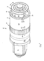
- a conveyor 2 for conveying articles of the tobacco processing industry is shown, which is formed in the illustrated embodiment as a rotary conveyor and has a conventional structure.
- the illustrated conveyor 2 has a stationary arranged, substantially cylindrical body 4, which has a substantially cylindrical outer or circumferential surface 4a and is also referred to as a control flange, a conveyor drum 6 which is rotatably mounted coaxially to the body 4 and opposite this in the direction of rotation R and an outer side 6a and adjacent thereto to the lateral surface 4a of the body 4 lying inside has 6 b, and a drive 8 to enable the conveyor drum 6 in rotation, on.
- two circumferentially extending and axially spaced annular groove rings 10, 11 are formed, each having a series of trough-shaped or groove-shaped receiving portions which extend in the axial direction and are adjacent.
- control flange or body 4 is in the figure of Fig. 1 the (as shown by Fig. 1 Right) portion of the conveyor drum 6 with the groove ring 10 largely cut away, so that only a still remaining narrow part of that groove ring 10 is shown.
- the trough-shaped or groove-shaped receiving portions on the Nutenkränzen 10, 11 for example, only one receiving portion by way of example by the reference numeral "12".
- the receiving sections 12 serve to receive articles of the tobacco processing industry, of which in Fig. 1 a filter cigarette 14 is shown by way of example.
- the articles lying in the receiving sections 12 are taken along in the transverse-axial direction corresponding to the direction of rotation R by the conveyor drum 6, which thus transports the articles along a partial circle.
- the two groove rings 10, 11 corresponding to two conveyor lines of the conveyor 2, wherein the features described below with reference to one of the two Nutenkränze 10, 11 features, details and benefits, unless otherwise stated, for the other Nutenkranz and from apply equally to this funding line.
- pairs of passages 16, 17 are provided, which extend from the bottom of the receiving portions 12 on the outer side 6a approximately radially through the shell of the conveyor drum 6 and open into an associated opening on the inner side 6b of the conveyor drum 6 , As Fig. 1 Further, in the bottom of each trough-shaped receiving portion 12, a pair of the passages 16, 17 opens so that the number of pairs of passages 16, 17 used in this embodiment is equal to the number of the receiving portions 12.
- Fig. 1 can also be seen, open in the illustrated embodiment, the passages 16, 17 in the bottom of the receiving portions 12 at a location adjacent to the ends thereof.
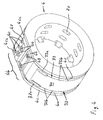
- Fig. 2 is particularly well recognized, open the passages 16, 17 on the inside 6b of the conveyor drum 6 in openings formed there, wherein in Fig. 2 the passages 16 and the associated openings are shown on the inside 6b and one of these openings is designated by the reference numeral "16a" as representative of those openings.
- FIGS. 1 and 2 can also be seen, in the illustrated embodiment in the lateral surface 4a of the body 4, two spaced apart and circumferentially extending grooves 18, 19 are formed, which are connected to a suction air source, not shown.
- the arrangement of the two grooves 18, 19 in the lateral surface 4a of the stationary body 4 and the openings formed by the passages 16, 17 on the inside 6b of the conveyor drum 6 is such that the of the passages 16 on the inside 6b of the conveyor drum 6 formed openings 16a with the groove 18 on the lateral surface 4a of the body 4 and the openings formed by the passages 17 on the inner side 6b of the conveyor drum 6 with the groove 19 on the lateral surface 4a of the body 4 are aligned.
- the groove 18 extends along the lateral surface 4a of the body 4, viewed in the direction of rotation R of the conveyor drum 6 from its beginning 18a to its end 18b approximately over a 3/4 circle, so that along this path each receiving portion 12 at the outside 6a of the conveyor drum 6 is subjected to negative pressure.
- a transport zone 18c which continues until the end 18b and 19b of the grooves 18, 19.
- the articles 14 remain in the receiving sections 12 by means of the negative pressure and are correspondingly taken along the transport zone 18c due to the continuously continued rotation of the conveyor drum 6 and thus conveyed until they then successively reach the end 18b, 19b of the grooves 18, Reach 19. There then stops the application of negative pressure and the receiving sections 12 are then successively briefly applied with overpressure.
- this is an axially extending groove 24 is provided, which, as shown by Fig. 2 , viewed in the direction of rotation R and thus in the circumferential direction of the lateral surface 4a of the body 4, a groove pitch is arranged downstream.
- This groove 24 is connected via a channel 25 (FIG. Fig. 2 ) connected to a compressed air source, not shown. If, with continued rotation of the conveyor drum 6, a receiving section 12 filled with an article 14 passes via its passages 16, 17 in fluid communication with the axial groove 24 in the lateral surface 4a of the body 4, an overpressure is created in the respective receiving section 12, whereby the article 14 this receiving portion 12 is delivered.
- a delivery of the article 14 from the conveyor drum 6 takes place.
- the articles 14 are delivered, in particular, to a subsequent further conveying device, not shown, or to a downstream station, likewise not shown, for further processing.
- the body 4 designed as a rotary body is arranged stationarily and thus stationary and rotationally fixed and therefore the same applies to the grooves 18, 19 and 24 formed in its lateral surface 4a. Accordingly, the arrangement of an upstream conveyor, not shown, which in the FIGS.
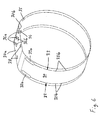
- Fig. 3 The fact that the stationary body is a body of revolution is particularly good Fig. 3 in which only the body 4 is shown in a modified embodiment.
- the body 4 is made by casting and the grooves 18, 19 and 24 are milled into the upper or lateral surface 4a of the molded body 4; Accordingly, preferably cast bodies or control flanges are used with milled grooves.
- the arrangement and formation of the grooves 18, 19 and 24 in the lateral surface 4a of the body 4 is determined by the length of the articles 14 to be transported. If the length of the articles 14 to be transported, for example, shorter than the distance between the grooves 18 and 19, which in turn determines the distance between the passages 16, 17 in each receiving portion 12 on the conveyor drum 6 in the illustrated embodiment, a secure adhesion of the article 14th in the receiving portions 12 and thus a reliable fixation can not be guaranteed. A similar problem also occurs in the case of excessively long lengths or excess lengths of the articles 14 to be transported, in spite of the effect of both passages 16, 17 in the receiving portions 12. Thus, in particular changes in the length of the article to be transported displacements or Changes in the location of the grooves 18, 19 and / or 24 on the lateral surface 4a of the body 4 be required, which would require a complete replacement of the relevant components of the conveyor 2.
- control plate 30 which is fixed in the circumferential direction on the lateral surface 4a of the body 4, as shown in the FIGS. 4 and 5 is shown.
- control plate 30 is also in a single representation in Fig. 6 in the closed state and in Fig. 7 shown in the expanded, lying flat and thus open state.
- the control plate 30 is formed in the illustrated embodiment as a sheet, sheet or plate-shaped, annularly closed flexible element and in particular as a foil or sheet, the thickness of the control plate 30 in particular less than 1 mm and preferably between 0.1 mm and 0, 8 mm. How the particular FIGS. 6 and 7 let recognize, in the illustrated embodiment, the control plate 30 has the shape of an elongated strip.
- the control plate 30 is dimensioned so that it covers the lateral surface 4a of the body 4 at least in that section where the relevant groove or relevant grooves are or are located, wherein in the region of the groove (s) the control plate 30 is provided with a passage opening is.
- a segment which is one of a groove 18 and a groove 19 (FIG. FIG. 1 ) formed pair of grooves FIG. 4 is not recognizable because of the overlap by the control plate 30.
- segment of the body 4 is thus an axial section which is associated with one of the two each one conveyor line on the conveyor drum 6 defining groove rings 10, 11 and in which it is for example the in FIG. 1 exposed and the Nutenkranz 10 assigned (in the representation of FIG. 1 right) end portion of the body 4 can act.
- the control plate 30 is provided with a first passage opening 32 and a second passage opening 33, wherein these two passage openings 32, 33 spaced and parallel to each other in the longitudinal direction of the control plate 30 (see. FIG. 7 ) corresponding to the circumferential direction of the lateral surface 4a of the body 4 (see. FIGS. 4 and 6 ) and at the same time the direction of rotation R of the conveyor drum 6 (see. FIGS. 1 and 2 ).
- the first passage opening 32 has a slot 32a, followed by a plurality of successively relatively narrow, discrete slots 32b connected.
- the second elongate passage opening 33 has a slot 33a, which is adjoined by a plurality of relatively narrow, discrete slots 33b lying one behind the other.
- the formation of the two passage openings 32, 33 in the control plate 30 and the arrangement of the control plate 30 on the lateral surface 4a of the body 4 made such that the slot 33a of the first passage opening 32 with the beginning 18a of the groove 18 (FIGS. FIG.
- the width of the slots 32b, 33b is significantly smaller than that of the slots 32a, 33a and the slots 32a, 33a have a much larger opening cross-section than at least one of the slots 32b, 33b.
- the width of the slots 32b, 33b may preferably be about 0.2 mm to 2 mm.
- the opening cross-section at least one slot 32b or 33b is significantly less than that of the slots 32a, 33a.
- This different dimensioning takes into account the fact that in the region of the task zone, in which the slots 32a, 33a are located when the control plate 30 is mounted, a relatively high suction force is needed to aspirate the articles, while in the subsequent transport zone, along which the slots 32b, 33b, the articles 14 located in the receiving sections 12 (cf. FIGS. 1 and 2 ) must be kept against accidental loosening or falling out and therefore only a small suction force is needed.
- the formation of successive discrete slots 32b, 33b in the control plate 30 has constructive advantages, since due to the presence of the intermediate, the slots from each other and integral with the remaining part of the control plate 30 sections no excessive weakening of the control plate 30 occurs, but the control plate 30th in the area of the slots essentially retains its strength.
- slits 32b, 33b can preferably be produced by means of a laser.
- FIGS. 6 and 7 can also be seen that in alignment and spaced from the end of the arrangement of the slots 32b and 33b, respectively, a further opening 34 and 35 is formed in the control plate.
- These further openings 34, 35 are in mounting the control plate 30 on the body 4 in registration with the axial groove 24 in the discharge zone (see. FIGS. 1 . 2 and 5 ), so that compressed air can be blown through those other openings 34, 35 in the control plate 30 for releasing and dispensing of the articles 14 from the receiving sections 12. Since a relatively high volume of air is needed in this process, the openings 34, 35 are each provided with a larger opening cross-section, as a comparison with the slots 32b, 33b, in particular in FIG. 7 lets recognize.
- FIG. 5 can recognize, several suction air channels 20 are provided, which open into the groove 18 and connected to the suction air source, not shown are.
- the groove 19 is provided with such Saugluftkanälen.
- control plate 30 in the fluid path between the lateral surface 4a of the body 4 and the inner side 6b of the conveyor drum 6 (see FIG. 2 ), wherein by the stationary arrangement of the control plate 30 on the lateral surface 4a of the body 4, the conveyor drum 6 performs a rotational movement not only relative to the body 4, but also with respect to the control plate 30.
- the strip-shaped control plate 30 is clamped onto the lateral surface 4a along the circumference of the body 4.
- the control plate 30 has a first end portion 30a and a second end portion 30b, wherein in the assembled state, such as FIGS. 4 to 6 recognize that these two end portions 30a, 30b overlap each other.
- the control plate 30 is aligned, fixed and tensioned on the body 4.
- An exact alignment of the control plate 30 with respect to the body 4 is important so that the passage openings 32, 33 and the other openings 34, 35 of the control plate 30 in correctly aligned arrangement relative to the corresponding grooves 18, 19 and 24 in the lateral surface 4a of the body 4 arrive. In order for this aligned arrangement to remain in operation, it must be the fixing of the control plate 30 on the lateral surface 4a of the body 4 so that no shifts are to be feared.
- FIG. 7 in each of the two end portions 30a, 30b first holes 36a and 37a and second holes 36b and 37b are formed.
- the hole pattern in both sections 30a, 30b is identical, so that in the mounted state, that is, when the two end portions 30a, 30b are overlapped with each other, the first holes 36a, 37a and the second holes 36b, 37b are superimposed, respectively FIG. 6 lets recognize.
- the control plate 30 is additionally provided with holes 38 in the region of its first end section 30a.
- FIGS. 4 and 5 can be further seen that in the mounted state, the two overlapping end portions 30a, 30b of the control plate 30 come to lie in a formed in the lateral surface 4a of the body 4 flattened portion 4b. Since there is always a "blank" area on the control flange or body 4, which is not provided with grooves, the flattened section 4b can be provided there on the lateral surface 4a.
- the lateral surface 4a is limited in the illustrated embodiment by circumferential, radially or flange slightly protruding edges 4c, the lateral slipping of the control plate 30 during its mounting on the lateral surface 4a Prevent body 4 and are further arranged in the flattened portion 4b of the lateral surface 4a upstanding alignment pins 40 which protrude when mounting the control plate 30 through the superimposed first holes 36 a, 36 b in the overlapping end portions 30 a, 30 b of the control plate 30, as shown in FIG FIGS. 4 and 5 in conjunction with the FIGS. 6 and 7 is apparent.
- the first holes 36a, 37a in the end portions 30a, 30b of the control plate 30 in conjunction with the alignment pin 40 on the flattened portion 4b of the lateral surface 4a of the body 4 serve to arrange the control plate 30 in the correct position on the lateral surface 4a of the body 4 during assembly ,
- a plate-shaped fastening means 42 is used in the illustrated embodiment, which is fixed to the flattened portion 4 b of the lateral surface 4 a of the body 4, as the FIGS. 4 and 5 reveal.
- the fixation of the fastening means 42 on the body 4 is effected by means of screws 44, which by the superimposed second holes 36b, 37b in the overlapping region of the two end portions 30a, 30b of the control plate 30 are plugged, as shown FIG. 4 in conjunction with the FIGS. 6 and 7 it can be seen, and are in threaded engagement with trained in the body, not shown in the drawings threaded holes.
- the fastening means 42 By screwing the fastening means 42 takes place a fixing of the control plate 30 in the region of its two overlapping end portions 30a, 30b by clamping engagement between the plate-shaped fastening means 42 and the flattened portion 4b of the lateral surface 4a of the body 4.
- the flattened portion 4b of the lateral surface 4a is bounded on both sides by corresponding portions 4cc of the edges 4c.
- control plate 30 For the attachment of the control plate 30, it is alternatively or additionally conceivable to arrange in the lateral surface 4a of the body 4, preferably plate-shaped, not shown in the figures magnetic elements and to provide the control plate 30 at least partially with magnetic material or to produce from such whereby the fixation of the control plate 30 on the lateral surface 4a of the body 4 is generated by magnetic action or at least supported.
- a tensioning device which has a plate-shaped clamping means 46 and the clamping means 46 on the body 4 fastened clamping screws 48 which are in screw engagement with correspondingly formed in the body 4, but not shown in the drawings tapped holes.
- the clamping means 46 is disposed in the region of the flattened portion 4b of the lateral surface 4a of the body 4 at a location in which the flattened portion 4b of the lateral surface 4a of the body 4 is provided with a recess 4d.
- This depression 4d is bridged by the control plate 30 in the region of its overlapping end sections 30a, 30b, on the upper side of which the clamping device 46 rests.
- the tensioning means 46 is moved in the direction of the depression 4d and thereby presses the control plate 30 at this point in the direction of the depression 4d.
- FIG. 8 is the body 4 in contrast to the representation of Fig. 4 shown without mounted control plate.
- Figure 8 indicates that between the two previously mentioned grooves 18, 19, a further groove 50 is provided which extends approximately centrally between the two grooves 18, 19 and parallel to these.
- the body 4 according to the in Fig. 8 illustrated embodiment allows the adaptation of the conveyor 2 to at least two different lengths corresponding to the axial distances between the grooves 18 and 50 or the grooves 50 and 19 (short length) on the one hand or between the grooves 18 and 19 (long) on the other.
- a further increase in format flexibility can be achieved by arranging more than in Fig. 8 achieve three grooves shown.
- the control plate 30 described not only serves to selectively influence the air flow, but also forms an advantageous measure for adapting the conveyor 2 to the length of the article 14 to be transported.
- the conveyor drum. 6 disassembled by a quick release, not shown, the clamping means 46 and the fastener 42 successively dissolved and the control plate 30 unwound.
- a new control plate with differently sized through holes 32, 33 and openings 34, 35 in adaptation to the new article is then placed on the lateral surface 4a of the body 4, aligned by means of the alignment pins 40, fastened by means of the fastener 42 and then tensioned by means of the clamping means 46 ,
Landscapes
- Manufacturing Of Cigar And Cigarette Tobacco (AREA)
Priority Applications (1)
| Application Number | Priority Date | Filing Date | Title |
|---|---|---|---|
| PL12183892T PL2570039T3 (pl) | 2011-09-13 | 2012-09-11 | Urządzenie przenośnikowe do transportu wyrobów przemysłu tytoniowego oraz zastosowanie elementu konstrukcyjnego w takim urządzeniu |
Applications Claiming Priority (1)
| Application Number | Priority Date | Filing Date | Title |
|---|---|---|---|
| DE201110082621 DE102011082621B4 (de) | 2011-09-13 | 2011-09-13 | Bauteil für eine zum Fördern von Artikeln der Tabak verarbeitenden Industrie ausgebildete Fördervorrichtung, Bauteilesatz mit mindestens zwei derartigen Bauteilen sowie Fördervorrichtung mit einem derartigen Bauteil |
Publications (3)
| Publication Number | Publication Date |
|---|---|
| EP2570039A2 true EP2570039A2 (fr) | 2013-03-20 |
| EP2570039A3 EP2570039A3 (fr) | 2014-04-30 |
| EP2570039B1 EP2570039B1 (fr) | 2018-06-13 |
Family
ID=46826345
Family Applications (1)
| Application Number | Title | Priority Date | Filing Date |
|---|---|---|---|
| EP12183892.4A Not-in-force EP2570039B1 (fr) | 2011-09-13 | 2012-09-11 | Dispositif d'acheminement conçu pour le transport d'articles de l'industrie de traitement du tabac ainsi que utilisation d'un composant dans un tel dispositif |
Country Status (4)
| Country | Link |
|---|---|
| EP (1) | EP2570039B1 (fr) |
| CN (1) | CN102987552B (fr) |
| DE (1) | DE102011082621B4 (fr) |
| PL (1) | PL2570039T3 (fr) |
Cited By (4)
| Publication number | Priority date | Publication date | Assignee | Title |
|---|---|---|---|---|
| DE102014214462A1 (de) | 2014-03-13 | 2015-09-17 | Hauni Maschinenbau Ag | Aufnahmevorrichtung zur Aufnahme von Artikeln der Tabak verarbeitenden Industrie |
| EP2921063A1 (fr) * | 2014-03-13 | 2015-09-23 | HAUNI Maschinenbau AG | Dispositif de réception d'articles de l'industrie de traitement du tabac |
| DE102014217448B3 (de) * | 2014-09-01 | 2016-01-14 | Hauni Maschinenbau Ag | Aufnahmevorrichtung zur Aufnahme von Artikeln der Tabak verarbeitenden Industrie |
| IT201900014352A1 (it) * | 2019-08-08 | 2021-02-08 | Gd Spa | Convogliatore e metodo di allineamento per articoli a forma di barretta |
Families Citing this family (2)
| Publication number | Priority date | Publication date | Assignee | Title |
|---|---|---|---|---|
| DE102013219574A1 (de) | 2013-09-27 | 2015-04-02 | Hauni Maschinenbau Ag | Transportvorrichtung zur Herstellung von stabförmigen Produkten der Tabak verarbeitenden Industrie |
| GB201407582D0 (en) * | 2014-04-30 | 2014-06-11 | British American Tobacco Co | A tobacco industry rod assembly apparatus |
Citations (1)
| Publication number | Priority date | Publication date | Assignee | Title |
|---|---|---|---|---|
| WO2010012420A1 (fr) | 2008-07-29 | 2010-02-04 | Hauni Maschinenbau Ag | Tambour de transport pour l'industrie de transformation du tabac |
Family Cites Families (10)
| Publication number | Priority date | Publication date | Assignee | Title |
|---|---|---|---|---|
| GB1078229A (en) * | 1965-05-20 | 1967-08-09 | Jan Antoni Rakowicz | Improvements relating to rod-like article transport apparatus |
| GB2090572B (en) * | 1980-12-18 | 1984-08-22 | Molins Ltd | Cigarette conveying drums |
| DE9302909U1 (de) * | 1993-02-27 | 1993-04-22 | Balcke-Dürr AG, 4030 Ratingen | Dampfbeheizter Plattenwärmetauscher |
| JP3368148B2 (ja) * | 1996-07-05 | 2003-01-20 | 日本たばこ産業株式会社 | ロッド部材の受け取り装置 |
| DE19949072A1 (de) * | 1999-10-12 | 2001-04-19 | Topack Verpacktech Gmbh | Verfahren zum Öffnen und Verfahren zum Schließen einer Oberführung, die an einer Förderbahn einer Verpackungseinrichtung zum Verpacken von stabförmigen Elementen der tabakverarbeitenden Industrie angeordnet ist und Vorrichtung hierzu |
| DE10012743C2 (de) * | 2000-03-16 | 2002-01-31 | Ditzel Gmbh | Transportwalze, insbesondere zum Führen von schmalen Papierbahnen in einer Zigarettenmaschine |
| EP1419705A1 (fr) * | 2001-06-19 | 2004-05-19 | Japan Tobacco Inc. | Eliminateur d'objet de type barre |
| DE102004047266A1 (de) * | 2004-09-24 | 2006-04-06 | Hauni Maschinenbau Ag | Vorrichtung zur Übergabe stabförmiger Artikel |
| ITBO20050779A1 (it) * | 2005-12-22 | 2006-03-23 | Gd Spa | Unita' convogliatrice di articoli da fumo |
| DE102010001362A1 (de) * | 2010-01-29 | 2011-08-04 | Hauni Maschinenbau AG, 21033 | Fördertrommel der Tabak verarbeitenden Industrie |
-
2011
- 2011-09-13 DE DE201110082621 patent/DE102011082621B4/de not_active Expired - Fee Related
-
2012
- 2012-09-11 EP EP12183892.4A patent/EP2570039B1/fr not_active Not-in-force
- 2012-09-11 PL PL12183892T patent/PL2570039T3/pl unknown
- 2012-09-13 CN CN201210462151.XA patent/CN102987552B/zh not_active Expired - Fee Related
Patent Citations (1)
| Publication number | Priority date | Publication date | Assignee | Title |
|---|---|---|---|---|
| WO2010012420A1 (fr) | 2008-07-29 | 2010-02-04 | Hauni Maschinenbau Ag | Tambour de transport pour l'industrie de transformation du tabac |
Cited By (8)
| Publication number | Priority date | Publication date | Assignee | Title |
|---|---|---|---|---|
| DE102014214462A1 (de) | 2014-03-13 | 2015-09-17 | Hauni Maschinenbau Ag | Aufnahmevorrichtung zur Aufnahme von Artikeln der Tabak verarbeitenden Industrie |
| EP2921063A1 (fr) * | 2014-03-13 | 2015-09-23 | HAUNI Maschinenbau AG | Dispositif de réception d'articles de l'industrie de traitement du tabac |
| CN105029690A (zh) * | 2014-03-13 | 2015-11-11 | 豪尼机械制造股份公司 | 用于容纳烟草加工业的物件的容纳装置 |
| DE102014217448B3 (de) * | 2014-09-01 | 2016-01-14 | Hauni Maschinenbau Ag | Aufnahmevorrichtung zur Aufnahme von Artikeln der Tabak verarbeitenden Industrie |
| EP2989908A1 (fr) | 2014-09-01 | 2016-03-02 | HAUNI Maschinenbau AG | Dispositif de reception d'articles de l'industrie de traitement du tabac |
| IT201900014352A1 (it) * | 2019-08-08 | 2021-02-08 | Gd Spa | Convogliatore e metodo di allineamento per articoli a forma di barretta |
| WO2021024222A1 (fr) * | 2019-08-08 | 2021-02-11 | G.D S.P.A. | Transporteur et procédé d'alignement d'articles en forme de tige |
| US12004556B2 (en) | 2019-08-08 | 2024-06-11 | G.D S.P.A. | Conveyor and method of aligning rod-shaped articles |
Also Published As
| Publication number | Publication date |
|---|---|
| EP2570039B1 (fr) | 2018-06-13 |
| DE102011082621A1 (de) | 2013-03-14 |
| EP2570039A3 (fr) | 2014-04-30 |
| DE102011082621B4 (de) | 2013-07-04 |
| CN102987552A (zh) | 2013-03-27 |
| PL2570039T3 (pl) | 2018-11-30 |
| CN102987552B (zh) | 2016-04-13 |
Similar Documents
| Publication | Publication Date | Title |
|---|---|---|
| DE102007003592B3 (de) | Saugwalze zum Transportieren von Flachmaterialzuschnitten | |
| DE69814387T2 (de) | Vorrichtung zum Schneiden von Kaschierelementen aus Materialbahnen | |
| DE3430739C2 (de) | Verfahren zum Schneiden und Ausstanzen sowie Zuführen von Aufklebern verschiedener Formen | |
| EP0071736B2 (fr) | Dispositif d'emballage pour la fabrication de découpes et pour amener celles-ci à une station d'emballage | |
| EP2570039B1 (fr) | Dispositif d'acheminement conçu pour le transport d'articles de l'industrie de traitement du tabac ainsi que utilisation d'un composant dans un tel dispositif | |
| DE102011007089B4 (de) | Rotationsfördervorrichtung und Verfahren zum Fördern von Artikeln der tabakverarbeitenden Industrie | |
| EP4013246B1 (fr) | Fourniture de parties de bande métallique pour segments de tabac | |
| EP2716171B1 (fr) | Dispositif de réception d'articles de l'industrie de traitement du tabac | |
| DE3711824C2 (fr) | ||
| DE102007032546A1 (de) | Kettenglied für eine umlaufende Transportkette einer Werkzeugmaschine, sowie Doppelendprofiler mit aus solchen Kettengliedern gebildeten Führungsketten | |
| EP2921062B1 (fr) | Dispositif de réception d'articles de l'industrie de traitement du tabac | |
| EP0203328A2 (fr) | Dispositif de déplacement des lames inférieures | |
| DE19857576A9 (de) | Vorrichtung zum Herumwickeln von Blättchen um stabförmige Gegenstände | |
| DE3209409A1 (de) | Papierbahn-fuehrungsvorrichtung | |
| DE2513867B2 (de) | Hochleistungs-Zigarettenstrangmaschine mit einem saugradförmigen Tabakstrang-Bandförderer | |
| EP1897454B1 (fr) | Agencement en forme de V d'ouvertures d'aspiration | |
| EP2989908B1 (fr) | Dispositif de reception d'articles de l'industrie de traitement du tabac | |
| EP2599395B1 (fr) | Tambour de transport, configuré et équipé pour le transport transversal-axial d'articles en forme de bâtonnets de l'industrie de traitement du tabac | |
| DE19959333B4 (de) | Vorrichtung zum Vereinzeln von Streifen und Verwendungen einer solchen Vorrichtung | |
| EP2921063B1 (fr) | Dispositif de réception d'articles de l'industrie de traitement du tabac | |
| DE102011007091A1 (de) | Vorrichtung und Verfahren zum Bearbeiten von stabförmigen Artikeln der tabakverarbeitenden Industrie | |
| DE19948955B4 (de) | Bahnschneidvorrichtung mit einer integrierten Messeranordnung in einer Rollenrotationsdruckmaschine | |
| EP3504987A1 (fr) | Dispositif de transport permettant de transporter des articles de l'industrie de traitement du tabac | |
| EP3262959A1 (fr) | Positionnement de produits en forme de tiges de l'industrie de traitement du tabac dans une machine d'insertion | |
| DE102014214462A1 (de) | Aufnahmevorrichtung zur Aufnahme von Artikeln der Tabak verarbeitenden Industrie |
Legal Events
| Date | Code | Title | Description |
|---|---|---|---|
| PUAI | Public reference made under article 153(3) epc to a published international application that has entered the european phase |
Free format text: ORIGINAL CODE: 0009012 |
|
| AK | Designated contracting states |
Kind code of ref document: A2 Designated state(s): AL AT BE BG CH CY CZ DE DK EE ES FI FR GB GR HR HU IE IS IT LI LT LU LV MC MK MT NL NO PL PT RO RS SE SI SK SM TR |
|
| AX | Request for extension of the european patent |
Extension state: BA ME |
|
| PUAL | Search report despatched |
Free format text: ORIGINAL CODE: 0009013 |
|
| AK | Designated contracting states |
Kind code of ref document: A3 Designated state(s): AL AT BE BG CH CY CZ DE DK EE ES FI FR GB GR HR HU IE IS IT LI LT LU LV MC MK MT NL NO PL PT RO RS SE SI SK SM TR |
|
| AX | Request for extension of the european patent |
Extension state: BA ME |
|
| RIC1 | Information provided on ipc code assigned before grant |
Ipc: A24C 5/32 20060101AFI20140326BHEP |
|
| 17P | Request for examination filed |
Effective date: 20141030 |
|
| RBV | Designated contracting states (corrected) |
Designated state(s): AL AT BE BG CH CY CZ DE DK EE ES FI FR GB GR HR HU IE IS IT LI LT LU LV MC MK MT NL NO PL PT RO RS SE SI SK SM TR |
|
| RAP1 | Party data changed (applicant data changed or rights of an application transferred) |
Owner name: HAUNI MASCHINENBAU GMBH |
|
| 17Q | First examination report despatched |
Effective date: 20160905 |
|
| GRAP | Despatch of communication of intention to grant a patent |
Free format text: ORIGINAL CODE: EPIDOSNIGR1 |
|
| INTG | Intention to grant announced |
Effective date: 20180122 |
|
| GRAS | Grant fee paid |
Free format text: ORIGINAL CODE: EPIDOSNIGR3 |
|
| GRAA | (expected) grant |
Free format text: ORIGINAL CODE: 0009210 |
|
| AK | Designated contracting states |
Kind code of ref document: B1 Designated state(s): AL AT BE BG CH CY CZ DE DK EE ES FI FR GB GR HR HU IE IS IT LI LT LU LV MC MK MT NL NO PL PT RO RS SE SI SK SM TR |
|
| REG | Reference to a national code |
Ref country code: GB Ref legal event code: FG4D Free format text: NOT ENGLISH |
|
| REG | Reference to a national code |
Ref country code: CH Ref legal event code: EP Ref country code: AT Ref legal event code: REF Ref document number: 1007529 Country of ref document: AT Kind code of ref document: T Effective date: 20180615 |
|
| REG | Reference to a national code |
Ref country code: DE Ref legal event code: R096 Ref document number: 502012012866 Country of ref document: DE |
|
| REG | Reference to a national code |
Ref country code: IE Ref legal event code: FG4D Free format text: LANGUAGE OF EP DOCUMENT: GERMAN |
|
| REG | Reference to a national code |
Ref country code: NL Ref legal event code: FP |
|
| REG | Reference to a national code |
Ref country code: LT Ref legal event code: MG4D |
|
| PG25 | Lapsed in a contracting state [announced via postgrant information from national office to epo] |
Ref country code: SE Free format text: LAPSE BECAUSE OF FAILURE TO SUBMIT A TRANSLATION OF THE DESCRIPTION OR TO PAY THE FEE WITHIN THE PRESCRIBED TIME-LIMIT Effective date: 20180613 Ref country code: BG Free format text: LAPSE BECAUSE OF FAILURE TO SUBMIT A TRANSLATION OF THE DESCRIPTION OR TO PAY THE FEE WITHIN THE PRESCRIBED TIME-LIMIT Effective date: 20180913 Ref country code: FI Free format text: LAPSE BECAUSE OF FAILURE TO SUBMIT A TRANSLATION OF THE DESCRIPTION OR TO PAY THE FEE WITHIN THE PRESCRIBED TIME-LIMIT Effective date: 20180613 Ref country code: CY Free format text: LAPSE BECAUSE OF FAILURE TO SUBMIT A TRANSLATION OF THE DESCRIPTION OR TO PAY THE FEE WITHIN THE PRESCRIBED TIME-LIMIT Effective date: 20180613 Ref country code: NO Free format text: LAPSE BECAUSE OF FAILURE TO SUBMIT A TRANSLATION OF THE DESCRIPTION OR TO PAY THE FEE WITHIN THE PRESCRIBED TIME-LIMIT Effective date: 20180913 Ref country code: LT Free format text: LAPSE BECAUSE OF FAILURE TO SUBMIT A TRANSLATION OF THE DESCRIPTION OR TO PAY THE FEE WITHIN THE PRESCRIBED TIME-LIMIT Effective date: 20180613 Ref country code: ES Free format text: LAPSE BECAUSE OF FAILURE TO SUBMIT A TRANSLATION OF THE DESCRIPTION OR TO PAY THE FEE WITHIN THE PRESCRIBED TIME-LIMIT Effective date: 20180613 |
|
| PG25 | Lapsed in a contracting state [announced via postgrant information from national office to epo] |
Ref country code: GR Free format text: LAPSE BECAUSE OF FAILURE TO SUBMIT A TRANSLATION OF THE DESCRIPTION OR TO PAY THE FEE WITHIN THE PRESCRIBED TIME-LIMIT Effective date: 20180914 Ref country code: HR Free format text: LAPSE BECAUSE OF FAILURE TO SUBMIT A TRANSLATION OF THE DESCRIPTION OR TO PAY THE FEE WITHIN THE PRESCRIBED TIME-LIMIT Effective date: 20180613 Ref country code: LV Free format text: LAPSE BECAUSE OF FAILURE TO SUBMIT A TRANSLATION OF THE DESCRIPTION OR TO PAY THE FEE WITHIN THE PRESCRIBED TIME-LIMIT Effective date: 20180613 Ref country code: RS Free format text: LAPSE BECAUSE OF FAILURE TO SUBMIT A TRANSLATION OF THE DESCRIPTION OR TO PAY THE FEE WITHIN THE PRESCRIBED TIME-LIMIT Effective date: 20180613 |
|
| PG25 | Lapsed in a contracting state [announced via postgrant information from national office to epo] |
Ref country code: CZ Free format text: LAPSE BECAUSE OF FAILURE TO SUBMIT A TRANSLATION OF THE DESCRIPTION OR TO PAY THE FEE WITHIN THE PRESCRIBED TIME-LIMIT Effective date: 20180613 Ref country code: RO Free format text: LAPSE BECAUSE OF FAILURE TO SUBMIT A TRANSLATION OF THE DESCRIPTION OR TO PAY THE FEE WITHIN THE PRESCRIBED TIME-LIMIT Effective date: 20180613 Ref country code: IS Free format text: LAPSE BECAUSE OF FAILURE TO SUBMIT A TRANSLATION OF THE DESCRIPTION OR TO PAY THE FEE WITHIN THE PRESCRIBED TIME-LIMIT Effective date: 20181013 Ref country code: EE Free format text: LAPSE BECAUSE OF FAILURE TO SUBMIT A TRANSLATION OF THE DESCRIPTION OR TO PAY THE FEE WITHIN THE PRESCRIBED TIME-LIMIT Effective date: 20180613 Ref country code: SK Free format text: LAPSE BECAUSE OF FAILURE TO SUBMIT A TRANSLATION OF THE DESCRIPTION OR TO PAY THE FEE WITHIN THE PRESCRIBED TIME-LIMIT Effective date: 20180613 |
|
| PG25 | Lapsed in a contracting state [announced via postgrant information from national office to epo] |
Ref country code: SM Free format text: LAPSE BECAUSE OF FAILURE TO SUBMIT A TRANSLATION OF THE DESCRIPTION OR TO PAY THE FEE WITHIN THE PRESCRIBED TIME-LIMIT Effective date: 20180613 |
|
| REG | Reference to a national code |
Ref country code: DE Ref legal event code: R097 Ref document number: 502012012866 Country of ref document: DE |
|
| PLBE | No opposition filed within time limit |
Free format text: ORIGINAL CODE: 0009261 |
|
| STAA | Information on the status of an ep patent application or granted ep patent |
Free format text: STATUS: NO OPPOSITION FILED WITHIN TIME LIMIT |
|
| PG25 | Lapsed in a contracting state [announced via postgrant information from national office to epo] |
Ref country code: MC Free format text: LAPSE BECAUSE OF FAILURE TO SUBMIT A TRANSLATION OF THE DESCRIPTION OR TO PAY THE FEE WITHIN THE PRESCRIBED TIME-LIMIT Effective date: 20180613 |
|
| REG | Reference to a national code |
Ref country code: CH Ref legal event code: PL |
|
| 26N | No opposition filed |
Effective date: 20190314 |
|
| GBPC | Gb: european patent ceased through non-payment of renewal fee |
Effective date: 20180913 |
|
| PG25 | Lapsed in a contracting state [announced via postgrant information from national office to epo] |
Ref country code: DK Free format text: LAPSE BECAUSE OF FAILURE TO SUBMIT A TRANSLATION OF THE DESCRIPTION OR TO PAY THE FEE WITHIN THE PRESCRIBED TIME-LIMIT Effective date: 20180613 Ref country code: SI Free format text: LAPSE BECAUSE OF FAILURE TO SUBMIT A TRANSLATION OF THE DESCRIPTION OR TO PAY THE FEE WITHIN THE PRESCRIBED TIME-LIMIT Effective date: 20180613 |
|
| REG | Reference to a national code |
Ref country code: BE Ref legal event code: MM Effective date: 20180930 |
|
| REG | Reference to a national code |
Ref country code: IE Ref legal event code: MM4A |
|
| PG25 | Lapsed in a contracting state [announced via postgrant information from national office to epo] |
Ref country code: LU Free format text: LAPSE BECAUSE OF NON-PAYMENT OF DUE FEES Effective date: 20180911 |
|
| PG25 | Lapsed in a contracting state [announced via postgrant information from national office to epo] |
Ref country code: IE Free format text: LAPSE BECAUSE OF NON-PAYMENT OF DUE FEES Effective date: 20180911 |
|
| PG25 | Lapsed in a contracting state [announced via postgrant information from national office to epo] |
Ref country code: LI Free format text: LAPSE BECAUSE OF NON-PAYMENT OF DUE FEES Effective date: 20180930 Ref country code: CH Free format text: LAPSE BECAUSE OF NON-PAYMENT OF DUE FEES Effective date: 20180930 Ref country code: BE Free format text: LAPSE BECAUSE OF NON-PAYMENT OF DUE FEES Effective date: 20180930 Ref country code: FR Free format text: LAPSE BECAUSE OF NON-PAYMENT OF DUE FEES Effective date: 20180930 |
|
| PG25 | Lapsed in a contracting state [announced via postgrant information from national office to epo] |
Ref country code: GB Free format text: LAPSE BECAUSE OF NON-PAYMENT OF DUE FEES Effective date: 20180913 |
|
| REG | Reference to a national code |
Ref country code: AT Ref legal event code: MM01 Ref document number: 1007529 Country of ref document: AT Kind code of ref document: T Effective date: 20180911 |
|
| PG25 | Lapsed in a contracting state [announced via postgrant information from national office to epo] |
Ref country code: AL Free format text: LAPSE BECAUSE OF FAILURE TO SUBMIT A TRANSLATION OF THE DESCRIPTION OR TO PAY THE FEE WITHIN THE PRESCRIBED TIME-LIMIT Effective date: 20180613 |
|
| PG25 | Lapsed in a contracting state [announced via postgrant information from national office to epo] |
Ref country code: MT Free format text: LAPSE BECAUSE OF FAILURE TO SUBMIT A TRANSLATION OF THE DESCRIPTION OR TO PAY THE FEE WITHIN THE PRESCRIBED TIME-LIMIT Effective date: 20180613 Ref country code: AT Free format text: LAPSE BECAUSE OF NON-PAYMENT OF DUE FEES Effective date: 20180911 |
|
| PG25 | Lapsed in a contracting state [announced via postgrant information from national office to epo] |
Ref country code: TR Free format text: LAPSE BECAUSE OF FAILURE TO SUBMIT A TRANSLATION OF THE DESCRIPTION OR TO PAY THE FEE WITHIN THE PRESCRIBED TIME-LIMIT Effective date: 20180613 |
|
| PG25 | Lapsed in a contracting state [announced via postgrant information from national office to epo] |
Ref country code: HU Free format text: LAPSE BECAUSE OF FAILURE TO SUBMIT A TRANSLATION OF THE DESCRIPTION OR TO PAY THE FEE WITHIN THE PRESCRIBED TIME-LIMIT; INVALID AB INITIO Effective date: 20120911 Ref country code: PT Free format text: LAPSE BECAUSE OF FAILURE TO SUBMIT A TRANSLATION OF THE DESCRIPTION OR TO PAY THE FEE WITHIN THE PRESCRIBED TIME-LIMIT Effective date: 20180613 |
|
| PG25 | Lapsed in a contracting state [announced via postgrant information from national office to epo] |
Ref country code: MK Free format text: LAPSE BECAUSE OF NON-PAYMENT OF DUE FEES Effective date: 20180613 |
|
| PGFP | Annual fee paid to national office [announced via postgrant information from national office to epo] |
Ref country code: NL Payment date: 20210925 Year of fee payment: 10 Ref country code: IT Payment date: 20210930 Year of fee payment: 10 |
|
| PGFP | Annual fee paid to national office [announced via postgrant information from national office to epo] |
Ref country code: PL Payment date: 20210820 Year of fee payment: 10 Ref country code: DE Payment date: 20210923 Year of fee payment: 10 |
|
| REG | Reference to a national code |
Ref country code: NL Ref legal event code: HC Owner name: KOERBER TECHNOLOGIES GMBH; DE Free format text: DETAILS ASSIGNMENT: CHANGE OF OWNER(S), CHANGE OF OWNER(S) NAME; FORMER OWNER NAME: HAUNI MASCHINENBAU GMBH Effective date: 20221031 |
|
| REG | Reference to a national code |
Ref country code: DE Ref legal event code: R119 Ref document number: 502012012866 Country of ref document: DE |
|
| REG | Reference to a national code |
Ref country code: NL Ref legal event code: MM Effective date: 20221001 |
|
| PG25 | Lapsed in a contracting state [announced via postgrant information from national office to epo] |
Ref country code: NL Free format text: LAPSE BECAUSE OF NON-PAYMENT OF DUE FEES Effective date: 20221001 |
|
| PG25 | Lapsed in a contracting state [announced via postgrant information from national office to epo] |
Ref country code: DE Free format text: LAPSE BECAUSE OF NON-PAYMENT OF DUE FEES Effective date: 20230401 |
|
| PG25 | Lapsed in a contracting state [announced via postgrant information from national office to epo] |
Ref country code: IT Free format text: LAPSE BECAUSE OF NON-PAYMENT OF DUE FEES Effective date: 20220911 |
|
| PG25 | Lapsed in a contracting state [announced via postgrant information from national office to epo] |
Ref country code: PL Free format text: LAPSE BECAUSE OF NON-PAYMENT OF DUE FEES Effective date: 20220911 |