EP2570153B1 - Procédés de formation d'un dispositif d'électrode avec impédance réduite - Google Patents
Procédés de formation d'un dispositif d'électrode avec impédance réduite Download PDFInfo
- Publication number
- EP2570153B1 EP2570153B1 EP12006458.9A EP12006458A EP2570153B1 EP 2570153 B1 EP2570153 B1 EP 2570153B1 EP 12006458 A EP12006458 A EP 12006458A EP 2570153 B1 EP2570153 B1 EP 2570153B1
- Authority
- EP
- European Patent Office
- Prior art keywords
- metallization
- primary
- nanospheres
- interface system
- thickness
- Prior art date
- Legal status (The legal status is an assumption and is not a legal conclusion. Google has not performed a legal analysis and makes no representation as to the accuracy of the status listed.)
- Not-in-force
Links
Images




Classifications
-
- A—HUMAN NECESSITIES
- A61—MEDICAL OR VETERINARY SCIENCE; HYGIENE
- A61B—DIAGNOSIS; SURGERY; IDENTIFICATION
- A61B5/00—Measuring for diagnostic purposes; Identification of persons
- A61B5/24—Detecting, measuring or recording bioelectric or biomagnetic signals of the body or parts thereof
- A61B5/25—Bioelectric electrodes therefor
- A61B5/263—Bioelectric electrodes therefor characterised by the electrode materials
-
- A—HUMAN NECESSITIES
- A61—MEDICAL OR VETERINARY SCIENCE; HYGIENE
- A61B—DIAGNOSIS; SURGERY; IDENTIFICATION
- A61B5/00—Measuring for diagnostic purposes; Identification of persons
- A61B5/68—Arrangements of detecting, measuring or recording means, e.g. sensors, in relation to patient
-
- A—HUMAN NECESSITIES
- A61—MEDICAL OR VETERINARY SCIENCE; HYGIENE
- A61N—ELECTROTHERAPY; MAGNETOTHERAPY; RADIATION THERAPY; ULTRASOUND THERAPY
- A61N1/00—Electrotherapy; Circuits therefor
- A61N1/02—Details
- A61N1/04—Electrodes
-
- A—HUMAN NECESSITIES
- A61—MEDICAL OR VETERINARY SCIENCE; HYGIENE
- A61N—ELECTROTHERAPY; MAGNETOTHERAPY; RADIATION THERAPY; ULTRASOUND THERAPY
- A61N1/00—Electrotherapy; Circuits therefor
- A61N1/02—Details
- A61N1/04—Electrodes
- A61N1/05—Electrodes for implantation or insertion into the body, e.g. heart electrode
-
- A—HUMAN NECESSITIES
- A61—MEDICAL OR VETERINARY SCIENCE; HYGIENE
- A61B—DIAGNOSIS; SURGERY; IDENTIFICATION
- A61B2562/00—Details of sensors; Constructional details of sensor housings or probes; Accessories for sensors
- A61B2562/02—Details of sensors specially adapted for in-vivo measurements
- A61B2562/0285—Nanoscale sensors
-
- A—HUMAN NECESSITIES
- A61—MEDICAL OR VETERINARY SCIENCE; HYGIENE
- A61B—DIAGNOSIS; SURGERY; IDENTIFICATION
- A61B2562/00—Details of sensors; Constructional details of sensor housings or probes; Accessories for sensors
- A61B2562/12—Manufacturing methods specially adapted for producing sensors for in-vivo measurements
- A61B2562/125—Manufacturing methods specially adapted for producing sensors for in-vivo measurements characterised by the manufacture of electrodes
-
- A—HUMAN NECESSITIES
- A61—MEDICAL OR VETERINARY SCIENCE; HYGIENE
- A61N—ELECTROTHERAPY; MAGNETOTHERAPY; RADIATION THERAPY; ULTRASOUND THERAPY
- A61N1/00—Electrotherapy; Circuits therefor
- A61N1/02—Details
- A61N1/04—Electrodes
- A61N1/05—Electrodes for implantation or insertion into the body, e.g. heart electrode
- A61N1/0526—Head electrodes
- A61N1/0529—Electrodes for brain stimulation
- A61N1/0534—Electrodes for deep brain stimulation
Definitions
- This invention relates generally to the electrode field, and more specifically to new and useful methods for forming an electrode device with reduced impedance. Such electrode are useful when fabricated into neural electrode assemblies for electrically stimulating body tissue or for recording physiological conditions of the body tissue.
- conductive electrodes such as electrodes for sensing and/or stimulation in neural probes, or other neural interface devices, have minimal impedance magnitude and impedance variance (e.g., for an electrode at different times).
- High impedance generally corresponds with several disadvantages. Sensing and recording electrodes with high impedance typically experience high thermal noise. Stimulation electrodes with high impedance require larger amounts of power during stimulation. Furthermore, a large amount of variance in impedance typically results in poor reliability and predictability during both sensing and stimulation modes of operation.
- Increasing the geometric surface area or "footprint" of an electrode is one technique to reduce impedance magnitude and variance, but that approach reduces the electrode's spatial resolution.
- Increasing the electrochemical surface area of an electrode is another technique for reducing impedance magnitude and variance, but at significant cost and resources.
- Current methods, such as electrodeposition or electroplating, for increasing a neural electrode's electrochemical surface area are often performed post-process on individual devices after microfabrication and, therefore, are relatively expensive. Electrodeposition can also be performed in batch processes, but this usually has issues with uniformity and repeatability. Also, reliability issues, such as changes in the charge carrying capacity over time or delamination between the modified electrode material and the underlying substrate, can be a concern.
- Nanotexturisation of gold surfaces and its application to neural implants by Andreas Frommhold, Thesis submitted to the University of Bir-mingham , discloses a development of a new method for the improvement of the interface properties of gold electrodes for neural implants. Nanosphere Lithography was used for masking layer deposition and anisotropic etching to fabricate nanostructures on the surface of electrodes.
- the present invention provides such new and useful methods for manufacturing electrode device, particularly those that are adapted for useful in neural interface applications.
- the invention relates to a neural interface system as claimed in claim 1.
- the invention also relates to a method for providing a neural interface system of the invention as claimed in claim 9.
- the present invention relates to improved low-cost, highly reliable methods for increasing the electrochemical surface area of neural electrodes.
- the invention relates to the deposition of a mono-layer of polymeric nanospheres on a dielectric substrate.
- the nanospheres self-assemble into generally repeating lattice forms with interstitial space between them.
- the metallization material that is left exposed between adjacent nanospheres is etched. Etching is only part-way through the thickness of the metallization.
- metallization material that are suitable for subsequent use as electrode in neural probes, and the like are deposited on the dielectric substrate, filling in the interstitial space between the arrayed nanospheres.
- the deposited metallization material builds into pyramidal-type structures that are shaped by the size of the nanospheres and the interstitial spacing between them.
- the nanospheres are then removed leaving behind the shaped metallization deposits of relatively high surface area.
- Such metallization deposits help to minimize impedance magnitude and impedance variance from one electrode to the next.
- a further improvement is to deposit alternating layers of metals into the interstitial space between the nanospheres.
- One of the metals for example gold
- the gold layers are then selectively etched to expose additional platinum surface area that was previously covered by the gold. This additional surface area is that which previously had gold both immediately above and below it.
- the invention relates to the neural interface system as claimed in claim 1. Preferred embodiments of the neural interface system of claim 1 are claimed in dependent claims 2 to 8. The invention also relates to a method for providing a neural interface system as claimed in claim 9. Preferred embodiments of the method are claimed in dependent claims 10 to 16.
- the present methods described herein are primarily referenced to forming a single electrode device, and in particular a neural electrode device. However, it should be understood that the present methods can be configured to form a plurality of electrode devices that are suitable for medical sensing or stimulation applications. In a preferred embodiment, the present methods can be adapted to manufacture an electrode that is suitable for any electrical stimulation technology and any recording or sensing technology having conductive electrodes, such as electrodes that are useful in physiological solutions. In that light, the methods described herein are readily adaptable to scaling to batch processes for forming a plurality of electrode devices with reduced impedance at relatively low cost and high uniformity from one electrode to the next. That is without increasing the geometric surface area (GSA) of the electrodes.
- GSA geometric surface area
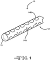
- FIG. 1 illustrates a neural interface system 10 according to the present invention.
- the neural interface system 10 comprises an electrode array 12 having a plurality of electrode sites 14A and 14B.
- the electrodes may be adapted to optimally sample (record) 14A or selectively activate (stimulate) 14B neural populations and may be individually or simultaneously activatable to create an activation pattern.
- the neural interface system 10 may further include a pre-molded component 15 onto which the neural interface array is attached or assembled that supports the electrode array 12.
- the electrode array 12 is coupled to the pre-molded component 15 such that the electrodes 14A, 14B are arranged both circumferentially around and axially there along.
- the neural interface system 10 of the present invention is preferably designed for deep brain stimulation and, more specifically, for deep brain stimulation with fine electrode site positioning, selectivity, tunability, and precise activation patterning.
- the neural interface system 10 may be alternatively used in any suitable environment (such as the spinal cord, peripheral nerve, muscle, or any other suitable anatomical location) and for any suitable reason.
- FIG. 2 shows the dielectric substrate 16 contacting a release layer 18 that is directly supported on a carrier 20.
- the dielectric layer 16 can be of a flexible thin material, preferably parylene, polyimide, silicon, or even a thin-film of silicon, or some combination of organic and inorganic dielectrics, but may alternatively be of any suitable material.
- the carrier 20 is preferably made of glass or silicon, but may alternatively be made from any other suitable material.
- the carrier 20 is may be flexible, rigid, or semi rigid depending on the microfabrication tooling (organic electronics equipment can increasingly use flexible substrates, whereas IC and MEMS microfabrication equipment use rigid silicon).
- a rigid carrier layer 20 has a thickness ranging from about 200 microns to about 925 microns, preferably greater than 500 microns.
- a metallization layer 22 is deposited on the upper or outer surface 16A of the dielectric substrate 16.
- the metallization 22 is shown as a continuous layer having a perimeter extending from a lower metallization surface supported on the upper substrate surface 16A to an upper metallization surface spaced from the lower metallization surface by a thickness of the perimeter.
- the metallization is substantially contiguous with the width and length (x- and y-axes) of the dielectric layer 16, although that is not necessary.
- the metallizations 22 can be deposited using any suitable thin film, semiconductor, microelectromechanical systems (MEMS) manufacturing technique or other microfabrication process, such as vapor deposition. Exemplary techniques and processes include evaporation and sputtering deposition.
- the metallizations layer 22 preferably includes a conductive material such as of gold (Au), platinum (Pt) or platinum-iridium, or any other metal, metal oxide, or conductive polymer having suitable electrically conductive properties.
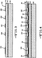
- FIG. 3 shows where the continuous metallization 22 has been patterned into a plurality of discrete metallization structures 22A, 22B, 22C, 22D, 22E, etc.
- the metallization layer 22 can be patterned through etching, liftoff deposition, or any other suitable thin film, semiconductor manufacturing, MEMS manufacturing, or other microfabrication process.
- the dielectric substrate 16, the release layer 18 and the carrier 20 can be flexible, semi-flexible, or rigid.
- the present method can further include patterning the metallization structures 22A, 22B, 22C, 22D, 22E, etc. to include conductive traces, bond pads, and other suitable conductive elements.
- a layer of nanospheres 26 has been deposited onto the dielectric substrate 16 to cover both the shaped metallizations 22A, 22B, 22C, 22D, 22E, etc. and the substrate surface 16A between adjacent metallizations.
- the nanospheres 26 form a high-density, high-resolution spatial pattern serving as a substantially uniform mask or template over the surface of the individual metallizations. That is because the nanospheres 26 are substantially identical in size and shape.
- the nanospheres 26 self-assemble into a tightly packed, uniform pattern.
- the present method can include depositing a monolayer of nanospheres 26 onto the metallizations 22A, 22B, 22C, 22D, 22E, etc. by drop wetting (direct application of the nanospheres in solution) and then allowing them to self-assemble into hexagonally packed patterns ( FIG. 8 ) upon de-wetting.
- This embodiment includes depositing a nanosphere solution including nanospheres and a solvent onto the metallization structures 22A, 22B, 22C, 22D, 22E, etc. The solvent is then evaporated.
- the solvent is preferably selected based on its viscosity, evaporation rate, and wettability on the metallizations patterned on the dielectric substrate 16.
- the solution includes polystyrene spheres mixed in a solvent of ethanol and de-ionized water.
- the ratio of ethanol to de-ionized water is approximately 4:1.
- the solution can include nanospheres 26 other than those of polystyrene and a suitable solvent other than a mixture of ethanol and de-ionized water.
- the solution is preferably dropped onto the dielectric substrate 16 such that a monolayer of nanospheres 26 is distributed substantially uniformly on the metallization structures 22A, 22B, 22C, 22D, 22E, etc.
- Depositing the nanosphere solution may be performed by using the Langmuir-Blodgett technique to transfer a pre-fabricated monolayer of nanospheres 26 onto the metallizations 22A, 22B, 22C, 22D, 22E, etc. patterned on the dielectric substrate 16.
- nanospheres 26 having a surface tension of ⁇ -NS are in a solvent having a surface tension of ⁇ -solvent. It is given that ⁇ -NS is less than ⁇ -solvent.
- a monolayer of nanospheres 26 forms at the exposed surface of metallizations 22A, 22B, 22C, 22D, 22E, etc. patterned on the dielectric substrate 16.
- the substrate 16 supported on the release layer 18 and the carrier 20 can be moved through the solution to transfer the monolayer of the nanospheres 26 thereto.
- a nanosphere solution e.g., 5% w/v solution
- the nanospheres 26 When applied to a patterned dielectric substrate 16 at room temperature on a horizontal surface, the nanospheres 26 will self-assemble along a contact line during the evaporation or de-wetting process.
- Evaporation of the solvent can occur unassisted or be accelerated with environmental changes, such as in temperature and pressure from that of an ambient atmosphere.
- a second preferred embodiment is where the nanospheres 26 are deposited onto the metallization structures 22A, 22B, 22C, 22D, 22E, etc. via spin-coating the above described nanosphere solution.
- the nanosphere solution can have a different viscosity, wettability, or other mixture ratio than that used with the drop-wetting or Langmuir-Blodgett technique.
- spin-coating can include a particular rate of spinning and/or acceleration.
- a series of recessed undulations 22A', 22B', 22C', 22D', 22E', etc. or upstanding undulations 22A" , 22B" , 22C" , 22D" , 22E” , etc. are formed on the surface of the metallizations 22A, 22B, 22C, 22D, 22E, etc.
- the recessed or upstanding undulations can be approximately pyramidal wave undulations, square wave undulations, approximately triangular wave undulations, or an undulation of any other suitable shape.
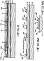
- FIGs. 5, 5A and 5A' show recessed undulations 22A', 22B', 22C', 22D', 22E', etc. that have been formed by etching 28 recesses 30 into the thickness of the respective metallizations 22A, 22B, 22C, 22D, 22E, etc. Etching the recesses 30 into the metallizations takes place beneath the interstitial spaces of the layer of assembled nanospheres 22. The result is undulations 22A" , 22B" , 22C” , 22D” , 22E” , etc. comprising recesses extending into the original thickness or height (h) of the metallization layers supported on the substrate 16.
- the nanospheres 26 have a diameter ranging from about one nanometer (nm) to about two nm.
- Etching can be performed with any suitable etching process.
- One advantage of etching is that it does not require any adhesion between the existing metallization layer and newly deposited conductive material.
- Platinum for example, is a commonly used biocompatible metal that can be dry etched using techniques described in U.S. Patent No. 6,323,132 with a reactive ion etcher.
- etching forms the recesses 30 having a depth extending part-way through the thickness of the metallization 22B from that portion of its upper surface of the metallization not contacted or otherwise covered by a nanosphere 26.
- the recesses 30 can extend from about 1% to about 99% into the thickness of the metallizations 22A, 22B, 22C, 22D, 22E, etc. More preferably, the recesses are from about 50% to about 90% into the original metallization thickness.
- the metallizations shown in FIG. 5A have a thickness measured from the upper surface 16A of the dielectric 18 to the upper surface of the as-deposited metallization of from about 0.25 micron to about 20 microns.
- FIGs 6, 6A and 6A' relate to an alternative method where the upstanding undulations 22A" , 22B" , 22C" , 22D'', 22E'', etc. are formed by depositing 28 additional metallization material (e.g., in a lift-off deposition) onto the metallizations 22A, 22B, 22C, 22D, 22E, etc. through the interstitial spaces between the nanospheres 26.
- Deposition 30 continues until the desired height of the added metallization material 32 measured from its base 32A supported on the upper surface of the original metallization 22B is achieved.
- the nanospheres have a diameter ranging from about 500 nm to about 5,000 nm.
- FIG. 7A illustrates a representative one of the undulations where the additional metallization material 32 forms a base on the upper surface of the metallization 22B and build-up in a pyramidal manner. That is without contacting the adjacent nanospheres 26, but while following their generally circular contour.
- the height of the upstanding undulations is preferably about 90% of the radius of the nanosphere. It has been discovered that this ratio provides maximum added surface area for the added metallization. That means the upstanding additional or secondary metallization material has a height ranging from about 225 nm to about 2,250 nm above the upper surface of the primary metallization 22.
- the added metallization does not grow so high as to prevent the subsequent removal of the nanospheres.
- FIG. 7B is a photograph showing how the deposited metallization material builds up from the upper surface of a metallization without contacting the nanospheres 26.
- the nanospheres 26 have been removed in the photograph, but the generally circular shape of one of them is delineated by the circle bordered by the deposited metallization material, which is seen as the off-white pyramidal bodies having somewhat triangular bases.
- the recessed undulations 22A', 22B', 22C', 22D', 22E', etc and extending 22A" , 22B" , 22C", 22D" , 22E'', etc on the respective metallizations are preferably bounded by the interstitial spaces of the nanospheres 26. Since the nanospheres 26 are substantially uniform in shape and arranged in a substantially uniform distribution in the layers of FIGs 5 and 6 supported on the upper surface of the metallizations 22A, 22B, 22C, 22D, 22E, etc., there is a substantially uniform distribution of interstitial spaces between the nanospheres 26. Consequently, the undulations 22A', 22B', 22C', 22D', 22E', etc. and 22A" , 22B" , 22C" , 22D" , 22E” , etc. are substantially uniformly distributed throughout the surface area of the shaped metallizations.
- the nanospheres 26 are removed from the dielectric substrate 18 after forming recesses or extending the undulations 22A', 22B', 22C', 22D', 22E', etc. and 22A", 22B'', 22C'', 22D'', 22E", etc. on the respective metallizations 22A, 22B, 22C, 22D, 22E, etc. or, the nanospheres 26 can be left on the metallizations.
- the undulations 22A', 22B', 22C', 22D', 22E', etc and 22A'', 22B" , 22C" , 22D" , 22E” , etc significantly increase the electrochemical surface area (ESA) of the electrode, particularly relative to the geometric surface area (GSA) of an electrode formed from one of the metallization according to the present invention.
- the interstitial spaces of the nanospheres are preferably arranged in a substantially uniform distribution, thereby enabling substantially uniform arrangement of the undulations.
- the undulating surface provides an increased ESA predicated on the diameter and packing arrangement of the nanospheres 26, and the depth of recess 30 for the recessed undulation 22A', 22B', 22C', 22D', 22E', etc. or the increased thickness of the deposited metallization material 32 for the extending undulations 22A", 22B" , 22C", 22D", 22E", etc.
- a increase area of ESA increase through either deposition or etching
- D s diameter of a sphere
- d m height of deposition or the depth of etch.
- the present invention methods additionally or alternatively include one or more of several variations described below.
- a further embodiment according to the present invention includes undercutting one or more alternating layers of patterned metal.
- the method includes: depositing a planar metallization layer stack (e.g.,Au/Pt,Au/Ir,or other Au stack) onto the dielectric substrate 16, and then selectively wet etching the Au metal.
- a planar metallization layer stack e.g.,Au/Pt,Au/Ir,or other Au stack
- An example of this is to deposit a layer of platinum 40 onto the dielectric layer (not shown in FIG. 10B ) using one of the methods previously described with respect to FIGs. 2A to 2C , 3 and 4 .
- a layer of gold 42 is deposited on top of the platinum 40 followed by a second layer of platinum.
- the nanospheres 26 are then removed and the gold 42 is wet etched. Etching serves to expose additional surface area of the platinum 40 that was previously positioned both above and below the gold. This is shown by the exposed surface 40A of the platinum layers 40 in FIG. 10B .
- d Au the depth of etch is depicted as d Au , which is less than the original thickness of the gold layer measured parallel to the plane of the dielectric substrate 16.
- iridium and titanium nitride are suitable metallization materials for use with this gold etching process. In that manner, gold etching serves to expose more of the non-Au metal surface area.
- FIGs. 11A and 11B relate to another embodiment of the method according to the present invention.
- This embodiment additionally or alternatively includes depositing an alternating combination of layers on the dielectric substrate (not shown in FIG. 11B ).
- alternating layer of platinum 40 and gold 42 are deposited one on top of the other until a stack of a desired height is achieved.
- the gold layers are wet etched to undercut and expose addition platinum surface area. As described above, it is important not to etch too much of the gold 42.
- the depth of etch is depicted as d Au , which is less than the original thickness of the gold layer measured parallel to the plane of the dielectric substrate 16.
- Enough gold must be left to serve as a structural pillar supporting the above platinum and gold layers.
- An example of this embodiment is alternating layers of Au/Pt/Au/Pt/Au/Pt stacked one on top of the other. Gold etching preferably forms more ESA.
- the preferred embodiments of the present methods include every combination and permutation of the various processes described above.
- the preferred embodiments of the present method can be executed by a computer program or other system including computer program code for controlling hardware (e.g., machines for deposition, sputtering) in an automated fashion.
- a neural interface device 10 with reduced impedance includes the dielectric substrate 16 supporting the electrode array 12 comprising the plurality of electrodes 14A, 14B.
- the dielectric substrate 16 is removed from the carrier 20.
- the release layer 18 facilitates this separation.
- the dielectric substrate 16 and the electrode array 12 are then formed into a desired shape of the neural interface system 10, which can be either planar or three-dimensional such as the cylindrical shape shown.
- the neural interface device 10 can be a planar probe with the electrode array 12, a cylindrical probe with the electrode array, a substantially planar or curved substrate with the electrode array, or any suitable electrode device.
- each electrode 14A, 14B has a substantially uniform undulating surface described above. At least a portion of the substantially uniform undulating surfaces of the electrodes 14A, 14B includes peaks and/or crevices (e.g., recesses) that are preferably distributed in a regular arrangement and, more preferably, in an approximately hexagonal arrangement as shown in FIGs. 5A, 5A' , 6A and 6A' .
- the undulating surfaces increases the electrochemical surface area of the electrodes 14A, 14B, thereby reducing their impedance and improving their functionality for stimulation and sensing purposes.
Landscapes
- Health & Medical Sciences (AREA)
- Life Sciences & Earth Sciences (AREA)
- General Health & Medical Sciences (AREA)
- Veterinary Medicine (AREA)
- Engineering & Computer Science (AREA)
- Biomedical Technology (AREA)
- Public Health (AREA)
- Animal Behavior & Ethology (AREA)
- Heart & Thoracic Surgery (AREA)
- Nuclear Medicine, Radiotherapy & Molecular Imaging (AREA)
- Radiology & Medical Imaging (AREA)
- Physics & Mathematics (AREA)
- Biophysics (AREA)
- Pathology (AREA)
- Medical Informatics (AREA)
- Molecular Biology (AREA)
- Surgery (AREA)
- Cardiology (AREA)
- Semiconductor Memories (AREA)
- Neurology (AREA)
- Electrodes Of Semiconductors (AREA)
- Electroplating Methods And Accessories (AREA)
Claims (16)
- Système d'interface neurale (10), qui comprend :a) un substrat (16) ;b) au moins une métallisation primaire supportée sur le substrat (16), la métallisation primaire (22) ayant un périmètre s'étendant d'une surface de métallisation inférieure supportée sur le substrat (16) à une surface de métallisation supérieure espacée de la surface de métallisation inférieure d'une épaisseur du périmètre, etc) dans lequel l'épaisseur de la métallisation primaire (22) est comprise dans la gamme allant de 0,25 µm à 20 µm ;- dans lequel la surface supérieure de la métallisation primaire (22) est caractérisée par une pluralité d'ondulations par des dépôts de nanosphères ;- lesdites ondulations comprenant une pluralité d'évidements (30) provenant de gravures s'étendant en partie jusque dans l'épaisseur de la métallisation primaire (22) ; et- lesdites ondulations comprenant une pluralité de métallisations secondaires verticales supportées sur la surface supérieure de la métallisation primaire (22) ;- dans lequel le substrat (16) supportant la métallisation primaire (22) avec les ondulations sur sa surface de métallisation supérieure est fourni sous une forme plane ou tridimensionnelle pour le contact avec un tissu corporel.
- Système d'interface neurale selon la revendication 1, dans lequel le substrat (16) est d'un matériau diélectrique sélectionné dans le groupe constitué du parylène, d'un polyimide, et du silicium.
- Système d'interface neurale selon la revendication 1 ou la revendication 2, dans lequel la métallisation primaire (22) est d'un matériau sélectionné dans le groupe constitué de l'or, du platine, et d'un alliage de platine/iridium.
- Système d'interface neurale selon l'une quelconque des revendications 1 à 3, dans lequel les évidements (30) s'étendent de 50 % à 90 % jusque dans l'épaisseur de la métallisation primaire (22) à partir de la surface supérieure de celle-ci et ne sont pas en communication les uns avec les autres.
- Système d'interface neurale selon l'une quelconque des revendications 1 à 4, dans lequel une deuxième épaisseur des métallisations secondaires verticales est comprise dans la gamme allant de 225 nm à 2 250 nm au-dessus de la surface supérieure de la métallisation primaire (22).
- Système d'interface neurale selon l'une quelconque des revendications 1 à 5, dans lequel la métallisation primaire et la métallisation secondaire sont du même matériau ou sont de matériaux différents.
- Système d'interface neurale selon la revendication 1, comprenant un matériau de métallisation secondaire relativement plus gravable sur la métallisation primaire et un matériau de métallisation tertiaire relativement moins gravable sur la métallisation secondaire sous la forme d'un empilement de métallisations, capable de former un système d'interface neurale ayant une surface spécifique des métallisations primaire et tertiaire plus importante lors du retrait d'une portion de la métallisation secondaire par gravure.
- Système d'interface neurale selon la revendication 7, dans lequel les matériaux de métallisation primaire et tertiaire sont identiques ou différents ; de préférence dans lequel les matériaux de métallisation primaire et tertiaire sont le platine et le matériau de métallisation secondaire est l'or.
- Méthode pour fournir un système d'interface neurale (10), comprenant les étapes consistant à :a) fournir un substrat (16) ;b) déposer au moins une métallisation primaire (22) supportée sur le substrat (16), la métallisation primaire (22) possédant un périmètre s'étendant d'une surface de métallisation inférieure supportée sur le substrat (16) à une surface de métallisation supérieure espacée de la surface de métallisation inférieure d'une épaisseur du périmètre comprise dans la gamme allant de 0,25 µm à 20 µm ;c) déposer une monocouche de nanosphères (26) entrant en contact avec la surface supérieure de la métallisation (22), etd) traiter la surface supérieure de la métallisation primaire (22) non mise en contact avec les nanosphères (26) afin de fournir de ce fait une pluralité d'ondulations ;- ladite méthode incluant le fait de fournir des ondulations en gravant des évidements (30) en partie à travers l'épaisseur de la métallisation primaire (22) à partir de la surface supérieure de celle-ci ; et- incluant en outre le fait de déposer une métallisation secondaire sur la métallisation primaire (22) afin de fournir de ce fait des ondulations comprenant une pluralité de métallisations secondaires verticales supportées sur la surface de la métallisation primaire (22).
- Méthode selon la revendication 9, incluant le fait de fournir des nanosphères (26) composées de polystyrène ; et/ou incluant le fait de fournir des nanosphères (26) ayant un diamètre compris dans la gamme allant de 20 nm à 1 000 nm.
- Méthode selon l'une quelconque des revendications 9 ou 10, incluant le fait de mélanger les nanosphères (26) avec de l'éthanol et de l'eau déminéralisée afin de former une solution de nanosphères qui est déposée sur les métallisations primaires (22).
- Méthode selon l'une quelconque des revendications 9 à 11, incluant le fait de fournir des évidements (30) s'étendant de 50 % à 90 % jusque dans l'épaisseur de la métallisation primaire (22) à partir de la surface supérieure de celle-ci et n'étant pas en communication les uns avec les autres.
- Méthode selon l'une quelconque des revendications 9 à 12, incluant le fait de fournir des nanosphères (26) ayant un diamètre compris dans la gamme allant de 500 nm à 5 000 nm.
- Méthode selon la revendication 13, incluant le fait de fournir une deuxième épaisseur des métallisations secondaires verticales comprise dans la gamme allant de 225 nm à 2 250 nm au-dessus de la surface supérieure de la métallisation primaire (22) ; et/ou incluant le fait d'interrompre le dépôt de la métallisation secondaire lorsque son épaisseur a atteint environ 90 % d'un rayon des nanosphères (26).
- Méthode selon l'une quelconque des revendications 9 à 14, incluant :i) le fait de déposer un matériau de métallisation secondaire relativement plus gravable sur la métallisation primaire (22), étape suivie par le fait de déposer un matériau de métallisation tertiaire relativement moins gravable sur le matériau de métallisation secondaire afin de former de ce fait un empilement de métallisations ; etii) le fait de graver l'empilement de métallisations afin de retirer une portion de la métallisation secondaire de sorte qu'une surface spécifique des matériaux de métallisation primaire et tertiaire plus importante soit obtenue.
- Méthode selon la revendication 15, incluant le fait de fournir les matériaux de métallisation primaire et tertiaire étant identiques ou différents ; incluant de préférence le fait de fournir les matériaux de métallisation primaire et tertiaire étant le platine et le matériau de métallisation secondaire étant l'or.
Applications Claiming Priority (2)
| Application Number | Priority Date | Filing Date | Title |
|---|---|---|---|
| US201161534787P | 2011-09-14 | 2011-09-14 | |
| US201161535852P | 2011-09-16 | 2011-09-16 |
Publications (2)
| Publication Number | Publication Date |
|---|---|
| EP2570153A1 EP2570153A1 (fr) | 2013-03-20 |
| EP2570153B1 true EP2570153B1 (fr) | 2017-09-13 |
Family
ID=46888883
Family Applications (1)
| Application Number | Title | Priority Date | Filing Date |
|---|---|---|---|
| EP12006458.9A Not-in-force EP2570153B1 (fr) | 2011-09-14 | 2012-09-14 | Procédés de formation d'un dispositif d'électrode avec impédance réduite |
Country Status (2)
| Country | Link |
|---|---|
| US (3) | US9192757B2 (fr) |
| EP (1) | EP2570153B1 (fr) |
Families Citing this family (16)
| Publication number | Priority date | Publication date | Assignee | Title |
|---|---|---|---|---|
| EP2570153B1 (fr) | 2011-09-14 | 2017-09-13 | NeuroNexus Technologies, Inc. | Procédés de formation d'un dispositif d'électrode avec impédance réduite |
| US11229789B2 (en) | 2013-05-30 | 2022-01-25 | Neurostim Oab, Inc. | Neuro activator with controller |
| EP3441109A1 (fr) | 2013-05-30 | 2019-02-13 | Graham H. Creasey | Timbre dermique souple pour système de neurostimuleur topique |
| EP2862595B1 (fr) | 2013-10-21 | 2017-07-19 | NeuroNexus Technologies, Inc. | Système d'électrode neuronal multicanal déployable omnidirectionnel |
| TWI569771B (zh) * | 2014-10-31 | 2017-02-11 | 國立清華大學 | 具細胞親和力與電容耦合性之立體電極 及包含其之生物探針 |
| US11077301B2 (en) | 2015-02-21 | 2021-08-03 | NeurostimOAB, Inc. | Topical nerve stimulator and sensor for bladder control |
| KR102382737B1 (ko) * | 2015-03-04 | 2022-04-06 | 한국전자통신연구원 | 신경 전극의 표면 개질 방법 |
| WO2016205610A1 (fr) * | 2015-06-18 | 2016-12-22 | The University Of Florida Research Foundation, Inc. | Lithographie à nanosphères réglables en 2d de nanostructures |
| AU2017222514A1 (en) | 2016-02-22 | 2018-08-30 | The Charles Stark Draper Laboratory, Inc. | Method of manufacturing an implantable neural electrode interface platform |
| DE102016222710A1 (de) * | 2016-11-18 | 2018-05-24 | Neuroloop GmbH | Implantierbare elektrische Kontaktanordnung |
| US11134868B2 (en) | 2017-03-17 | 2021-10-05 | Medtronic Minimed, Inc. | Metal pillar device structures and methods for making and using them in electrochemical and/or electrocatalytic applications |
| WO2019094365A1 (fr) | 2017-11-07 | 2019-05-16 | Neurostim Oab, Inc. | Activateur de nerf non invasif à circuit adaptatif |
| CA3144957A1 (fr) | 2019-06-26 | 2020-12-30 | Neurostim Technologies Llc | Activateur de nerf non invasif a circuit adaptatif |
| US11523757B2 (en) | 2019-08-01 | 2022-12-13 | Medtronic Minimed, Inc. | Micro-pillar working electrodes design to reduce backflow of hydrogen peroxide in glucose sensor |
| WO2021126921A1 (fr) | 2019-12-16 | 2021-06-24 | Neurostim Solutions, Llc | Activateur nerveux non invasif à distribution de charge amplifiée |
| WO2026020046A1 (fr) * | 2024-07-18 | 2026-01-22 | Blackrock Microsystems, Inc. | Systèmes intégrés implantables et procédés de fabrication associés |
Family Cites Families (25)
| Publication number | Priority date | Publication date | Assignee | Title |
|---|---|---|---|---|
| US6323132B1 (en) | 1998-01-13 | 2001-11-27 | Applied Materials, Inc. | Etching methods for anisotropic platinum profile |
| US6350388B1 (en) * | 1999-08-19 | 2002-02-26 | Micron Technology, Inc. | Method for patterning high density field emitter tips |
| AU2002305357A1 (en) * | 2001-05-01 | 2002-11-11 | Second Sight, Llc | High-density array of micro-machined electrodes for neural stimulation |
| WO2006007909A1 (fr) * | 2004-07-22 | 2006-01-26 | Universität Konstanz | Supports de donnees |
| AU2007261384B2 (en) * | 2006-06-19 | 2011-08-04 | Second Sight Medical Products, Inc. | Electrode with increased stability and method of manufacturing the same |
| CN101516437A (zh) * | 2006-09-22 | 2009-08-26 | 皇家飞利浦电子股份有限公司 | 可植入的多电极装置 |
| US8731673B2 (en) | 2007-02-26 | 2014-05-20 | Sapiens Steering Brain Stimulation B.V. | Neural interface system |
| US8565894B2 (en) | 2007-10-17 | 2013-10-22 | Neuronexus Technologies, Inc. | Three-dimensional system of electrode leads |
| WO2010008627A1 (fr) * | 2008-03-28 | 2010-01-21 | Georgia Tech Research Corporation | Rangées d'électrodes et procédé de production et d'utilisation associé |
| US8886279B2 (en) * | 2008-06-03 | 2014-11-11 | University Of Utah Research Foundation | High aspect ratio microelectrode arrays enabled to have customizable lengths and methods of making the same |
| US8636884B2 (en) * | 2008-09-15 | 2014-01-28 | Abbott Diabetes Care Inc. | Cationic polymer based wired enzyme formulations for use in analyte sensors |
| US8781576B2 (en) * | 2009-03-17 | 2014-07-15 | Cardiothrive, Inc. | Device and method for reducing patient transthoracic impedance for the purpose of delivering a therapeutic current |
| WO2011053254A1 (fr) * | 2009-10-30 | 2011-05-05 | Agency For Science, Technology And Research | Elément de sonde et procédé de formation d'un élément de sonde |
| EP2513953B1 (fr) * | 2009-12-16 | 2017-10-18 | The Board of Trustees of the University of Illionis | Électrophysiologie faisant intervenir des équipements électroniques conformes |
| US20110288391A1 (en) * | 2010-05-19 | 2011-11-24 | Purdue Research Foundation | Titanium-Based Multi-Channel Microelectrode Array for Electrophysiological Recording and Stimulation of Neural Tissue |
| AU2011329283B2 (en) * | 2010-11-15 | 2014-09-25 | The Government of the United State of America, as represented by the Secretary of the Navy | Perforated contact electrode on vertical nanowire array |
| US9782091B2 (en) * | 2011-07-25 | 2017-10-10 | Neuronexus Technologies, Inc. | Opto-electrical device for artifact reduction |
| EP2570153B1 (fr) * | 2011-09-14 | 2017-09-13 | NeuroNexus Technologies, Inc. | Procédés de formation d'un dispositif d'électrode avec impédance réduite |
| KR20130057721A (ko) * | 2011-11-24 | 2013-06-03 | 한국전자통신연구원 | 바이오 센서, 이를 이용한 바이오 물질 검출 장치 및 검출 방법 |
| US9242087B2 (en) * | 2012-06-01 | 2016-01-26 | The Regents Of The University Of Michigan | Nanocomposites for neural prosthetics devices |
| JP5814868B2 (ja) * | 2012-06-29 | 2015-11-17 | 株式会社東芝 | 磁気記録媒体の製造方法 |
| US9883826B2 (en) * | 2012-07-16 | 2018-02-06 | Diagnostic Biochips, Inc. | In vivo biosensor |
| KR20150046878A (ko) * | 2013-10-23 | 2015-05-04 | 한국전자통신연구원 | 계면활성제를 이용한 다공성 신경전극 및 이의 제조방법 |
| KR102382737B1 (ko) * | 2015-03-04 | 2022-04-06 | 한국전자통신연구원 | 신경 전극의 표면 개질 방법 |
| FR3055706B1 (fr) * | 2016-09-05 | 2018-09-07 | Commissariat A L'energie Atomique Et Aux Energies Alternatives | Surface optique antireflet, structuree et a grande duree de vie, et son procede de realisation |
-
2012
- 2012-09-14 EP EP12006458.9A patent/EP2570153B1/fr not_active Not-in-force
- 2012-09-14 US US13/617,355 patent/US9192757B2/en active Active
-
2015
- 2015-11-16 US US14/941,784 patent/US10052476B2/en active Active
-
2018
- 2018-08-20 US US15/999,381 patent/US11096614B2/en not_active Expired - Fee Related
Non-Patent Citations (1)
| Title |
|---|
| None * |
Also Published As
| Publication number | Publication date |
|---|---|
| US11096614B2 (en) | 2021-08-24 |
| EP2570153A1 (fr) | 2013-03-20 |
| US10052476B2 (en) | 2018-08-21 |
| US20190038892A1 (en) | 2019-02-07 |
| US9192757B2 (en) | 2015-11-24 |
| US20130066182A1 (en) | 2013-03-14 |
| US20160067473A1 (en) | 2016-03-10 |
Similar Documents
| Publication | Publication Date | Title |
|---|---|---|
| EP2570153B1 (fr) | Procédés de formation d'un dispositif d'électrode avec impédance réduite | |
| US8865288B2 (en) | Micro-needle arrays having non-planar tips and methods of manufacture thereof | |
| US20090301994A1 (en) | Methods for Wafer Scale Processing of Needle Array Devices | |
| US7951300B2 (en) | Water-scale needle array | |
| Bhandari et al. | Wafer-scale fabrication of penetrating neural microelectrode arrays | |
| US11013437B2 (en) | Nanopatterned biosensor electrode for enhanced sensor signal and sensitivity | |
| Bhandari et al. | A novel method of fabricating convoluted shaped electrode arrays for neural and retinal prostheses | |
| US8187865B2 (en) | Nanowire sensor, sensor array, and method for making the same | |
| EP3420580A1 (fr) | Fabrication de nanoparticules | |
| US10775335B2 (en) | Nanopatterned biosensor electrode for enhanced sensor signal and sensitivity | |
| US9867979B2 (en) | Three-dimensional multi-electrode array | |
| US10856764B2 (en) | Method for forming a multielectrode conformal penetrating array | |
| US12324909B2 (en) | Neural electrode based on three-dimensional structure of flexible substrate, and manufacturing method therefor | |
| US9165722B2 (en) | Method for producing a capacitor including an array of nanocapacitors | |
| CN112717273A (zh) | 一种微柱状结构神经电刺激电极及其制备方法 | |
| WO2017157874A1 (fr) | Dispositif photovoltaïque destiné à la stimulation de cellules et/ou de réactions électrochimiques | |
| JP2024036487A (ja) | 微小電気機械システム構造及びそれらの応用 | |
| CN107210319A (zh) | 大规模低成本纳米传感器、纳米针和纳米泵阵列 | |
| Bhandari et al. | Wafer-scale processed, low impedance, neural arrays with varying length microelectrodes | |
| CN101804960A (zh) | 一种超微锥电极阵列及其制备方法 | |
| Bhandari et al. | Wafer level processing of silicon arrays for implantable medical devices | |
| EP4379397B1 (fr) | Procédé de production d'un substrat comprenant de multiples pointes pour microscopie à sonde de balayage | |
| Wu et al. | Microfabrication of high-density microelectrode arrays for peripheral intraneural applications | |
| Pemba et al. | SU-8/silicon hybrid three dimensional intraneural electrode array | |
| Yao et al. | Design and Fabrication of Micro Multi-Probe Electrode Arrays |
Legal Events
| Date | Code | Title | Description |
|---|---|---|---|
| PUAI | Public reference made under article 153(3) epc to a published international application that has entered the european phase |
Free format text: ORIGINAL CODE: 0009012 |
|
| AK | Designated contracting states |
Kind code of ref document: A1 Designated state(s): AL AT BE BG CH CY CZ DE DK EE ES FI FR GB GR HR HU IE IS IT LI LT LU LV MC MK MT NL NO PL PT RO RS SE SI SK SM TR |
|
| AX | Request for extension of the european patent |
Extension state: BA ME |
|
| 17P | Request for examination filed |
Effective date: 20130920 |
|
| RBV | Designated contracting states (corrected) |
Designated state(s): AL AT BE BG CH CY CZ DE DK EE ES FI FR GB GR HR HU IE IS IT LI LT LU LV MC MK MT NL NO PL PT RO RS SE SI SK SM TR |
|
| 17Q | First examination report despatched |
Effective date: 20140930 |
|
| RAP1 | Party data changed (applicant data changed or rights of an application transferred) |
Owner name: GREATBATCH LTD. |
|
| RAP1 | Party data changed (applicant data changed or rights of an application transferred) |
Owner name: NEURONEXUS TECHNOLOGIES, INC. |
|
| GRAP | Despatch of communication of intention to grant a patent |
Free format text: ORIGINAL CODE: EPIDOSNIGR1 |
|
| RIC1 | Information provided on ipc code assigned before grant |
Ipc: A61B 5/04 20060101ALN20161021BHEP Ipc: A61N 1/36 20060101ALN20161021BHEP Ipc: A61N 1/05 20060101AFI20161021BHEP |
|
| GRAJ | Information related to disapproval of communication of intention to grant by the applicant or resumption of examination proceedings by the epo deleted |
Free format text: ORIGINAL CODE: EPIDOSDIGR1 |
|
| INTG | Intention to grant announced |
Effective date: 20161125 |
|
| INTC | Intention to grant announced (deleted) | ||
| GRAP | Despatch of communication of intention to grant a patent |
Free format text: ORIGINAL CODE: EPIDOSNIGR1 |
|
| RIC1 | Information provided on ipc code assigned before grant |
Ipc: A61N 1/05 20060101AFI20170118BHEP Ipc: A61B 5/04 20060101ALN20170118BHEP Ipc: A61N 1/36 20060101ALN20170118BHEP |
|
| GRAJ | Information related to disapproval of communication of intention to grant by the applicant or resumption of examination proceedings by the epo deleted |
Free format text: ORIGINAL CODE: EPIDOSDIGR1 |
|
| INTG | Intention to grant announced |
Effective date: 20170206 |
|
| GRAP | Despatch of communication of intention to grant a patent |
Free format text: ORIGINAL CODE: EPIDOSNIGR1 |
|
| INTC | Intention to grant announced (deleted) | ||
| RIC1 | Information provided on ipc code assigned before grant |
Ipc: A61N 1/05 20060101AFI20170309BHEP Ipc: A61B 5/04 20060101ALN20170309BHEP Ipc: A61N 1/36 20060101ALN20170309BHEP |
|
| INTG | Intention to grant announced |
Effective date: 20170327 |
|
| RAP1 | Party data changed (applicant data changed or rights of an application transferred) |
Owner name: NEURONEXUS TECHNOLOGIES, INC. |
|
| GRAS | Grant fee paid |
Free format text: ORIGINAL CODE: EPIDOSNIGR3 |
|
| GRAA | (expected) grant |
Free format text: ORIGINAL CODE: 0009210 |
|
| AK | Designated contracting states |
Kind code of ref document: B1 Designated state(s): AL AT BE BG CH CY CZ DE DK EE ES FI FR GB GR HR HU IE IS IT LI LT LU LV MC MK MT NL NO PL PT RO RS SE SI SK SM TR |
|
| REG | Reference to a national code |
Ref country code: GB Ref legal event code: FG4D |
|
| REG | Reference to a national code |
Ref country code: CH Ref legal event code: EP |
|
| REG | Reference to a national code |
Ref country code: FR Ref legal event code: PLFP Year of fee payment: 6 |
|
| REG | Reference to a national code |
Ref country code: IE Ref legal event code: FG4D |
|
| REG | Reference to a national code |
Ref country code: AT Ref legal event code: REF Ref document number: 927555 Country of ref document: AT Kind code of ref document: T Effective date: 20171015 |
|
| REG | Reference to a national code |
Ref country code: DE Ref legal event code: R096 Ref document number: 602012037186 Country of ref document: DE |
|
| REG | Reference to a national code |
Ref country code: NL Ref legal event code: MP Effective date: 20170913 |
|
| REG | Reference to a national code |
Ref country code: LT Ref legal event code: MG4D |
|
| PG25 | Lapsed in a contracting state [announced via postgrant information from national office to epo] |
Ref country code: FI Free format text: LAPSE BECAUSE OF FAILURE TO SUBMIT A TRANSLATION OF THE DESCRIPTION OR TO PAY THE FEE WITHIN THE PRESCRIBED TIME-LIMIT Effective date: 20170913 Ref country code: SE Free format text: LAPSE BECAUSE OF FAILURE TO SUBMIT A TRANSLATION OF THE DESCRIPTION OR TO PAY THE FEE WITHIN THE PRESCRIBED TIME-LIMIT Effective date: 20170913 Ref country code: HR Free format text: LAPSE BECAUSE OF FAILURE TO SUBMIT A TRANSLATION OF THE DESCRIPTION OR TO PAY THE FEE WITHIN THE PRESCRIBED TIME-LIMIT Effective date: 20170913 Ref country code: LT Free format text: LAPSE BECAUSE OF FAILURE TO SUBMIT A TRANSLATION OF THE DESCRIPTION OR TO PAY THE FEE WITHIN THE PRESCRIBED TIME-LIMIT Effective date: 20170913 Ref country code: NO Free format text: LAPSE BECAUSE OF FAILURE TO SUBMIT A TRANSLATION OF THE DESCRIPTION OR TO PAY THE FEE WITHIN THE PRESCRIBED TIME-LIMIT Effective date: 20171213 |
|
| REG | Reference to a national code |
Ref country code: AT Ref legal event code: MK05 Ref document number: 927555 Country of ref document: AT Kind code of ref document: T Effective date: 20170913 |
|
| PG25 | Lapsed in a contracting state [announced via postgrant information from national office to epo] |
Ref country code: ES Free format text: LAPSE BECAUSE OF FAILURE TO SUBMIT A TRANSLATION OF THE DESCRIPTION OR TO PAY THE FEE WITHIN THE PRESCRIBED TIME-LIMIT Effective date: 20170913 Ref country code: GR Free format text: LAPSE BECAUSE OF FAILURE TO SUBMIT A TRANSLATION OF THE DESCRIPTION OR TO PAY THE FEE WITHIN THE PRESCRIBED TIME-LIMIT Effective date: 20171214 Ref country code: RS Free format text: LAPSE BECAUSE OF FAILURE TO SUBMIT A TRANSLATION OF THE DESCRIPTION OR TO PAY THE FEE WITHIN THE PRESCRIBED TIME-LIMIT Effective date: 20170913 Ref country code: LV Free format text: LAPSE BECAUSE OF FAILURE TO SUBMIT A TRANSLATION OF THE DESCRIPTION OR TO PAY THE FEE WITHIN THE PRESCRIBED TIME-LIMIT Effective date: 20170913 Ref country code: BG Free format text: LAPSE BECAUSE OF FAILURE TO SUBMIT A TRANSLATION OF THE DESCRIPTION OR TO PAY THE FEE WITHIN THE PRESCRIBED TIME-LIMIT Effective date: 20171213 |
|
| PG25 | Lapsed in a contracting state [announced via postgrant information from national office to epo] |
Ref country code: NL Free format text: LAPSE BECAUSE OF FAILURE TO SUBMIT A TRANSLATION OF THE DESCRIPTION OR TO PAY THE FEE WITHIN THE PRESCRIBED TIME-LIMIT Effective date: 20170913 |
|
| PG25 | Lapsed in a contracting state [announced via postgrant information from national office to epo] |
Ref country code: PL Free format text: LAPSE BECAUSE OF FAILURE TO SUBMIT A TRANSLATION OF THE DESCRIPTION OR TO PAY THE FEE WITHIN THE PRESCRIBED TIME-LIMIT Effective date: 20170913 Ref country code: RO Free format text: LAPSE BECAUSE OF FAILURE TO SUBMIT A TRANSLATION OF THE DESCRIPTION OR TO PAY THE FEE WITHIN THE PRESCRIBED TIME-LIMIT Effective date: 20170913 Ref country code: CZ Free format text: LAPSE BECAUSE OF FAILURE TO SUBMIT A TRANSLATION OF THE DESCRIPTION OR TO PAY THE FEE WITHIN THE PRESCRIBED TIME-LIMIT Effective date: 20170913 |
|
| REG | Reference to a national code |
Ref country code: CH Ref legal event code: PL |
|
| PG25 | Lapsed in a contracting state [announced via postgrant information from national office to epo] |
Ref country code: SK Free format text: LAPSE BECAUSE OF FAILURE TO SUBMIT A TRANSLATION OF THE DESCRIPTION OR TO PAY THE FEE WITHIN THE PRESCRIBED TIME-LIMIT Effective date: 20170913 Ref country code: AT Free format text: LAPSE BECAUSE OF FAILURE TO SUBMIT A TRANSLATION OF THE DESCRIPTION OR TO PAY THE FEE WITHIN THE PRESCRIBED TIME-LIMIT Effective date: 20170913 Ref country code: EE Free format text: LAPSE BECAUSE OF FAILURE TO SUBMIT A TRANSLATION OF THE DESCRIPTION OR TO PAY THE FEE WITHIN THE PRESCRIBED TIME-LIMIT Effective date: 20170913 Ref country code: SM Free format text: LAPSE BECAUSE OF FAILURE TO SUBMIT A TRANSLATION OF THE DESCRIPTION OR TO PAY THE FEE WITHIN THE PRESCRIBED TIME-LIMIT Effective date: 20170913 Ref country code: IS Free format text: LAPSE BECAUSE OF FAILURE TO SUBMIT A TRANSLATION OF THE DESCRIPTION OR TO PAY THE FEE WITHIN THE PRESCRIBED TIME-LIMIT Effective date: 20180113 Ref country code: IT Free format text: LAPSE BECAUSE OF FAILURE TO SUBMIT A TRANSLATION OF THE DESCRIPTION OR TO PAY THE FEE WITHIN THE PRESCRIBED TIME-LIMIT Effective date: 20170913 |
|
| REG | Reference to a national code |
Ref country code: DE Ref legal event code: R097 Ref document number: 602012037186 Country of ref document: DE |
|
| REG | Reference to a national code |
Ref country code: IE Ref legal event code: MM4A |
|
| REG | Reference to a national code |
Ref country code: BE Ref legal event code: MM Effective date: 20170930 |
|
| PG25 | Lapsed in a contracting state [announced via postgrant information from national office to epo] |
Ref country code: MC Free format text: LAPSE BECAUSE OF FAILURE TO SUBMIT A TRANSLATION OF THE DESCRIPTION OR TO PAY THE FEE WITHIN THE PRESCRIBED TIME-LIMIT Effective date: 20170913 Ref country code: LU Free format text: LAPSE BECAUSE OF NON-PAYMENT OF DUE FEES Effective date: 20170914 |
|
| PLBE | No opposition filed within time limit |
Free format text: ORIGINAL CODE: 0009261 |
|
| STAA | Information on the status of an ep patent application or granted ep patent |
Free format text: STATUS: NO OPPOSITION FILED WITHIN TIME LIMIT |
|
| PG25 | Lapsed in a contracting state [announced via postgrant information from national office to epo] |
Ref country code: LI Free format text: LAPSE BECAUSE OF NON-PAYMENT OF DUE FEES Effective date: 20170930 Ref country code: DK Free format text: LAPSE BECAUSE OF FAILURE TO SUBMIT A TRANSLATION OF THE DESCRIPTION OR TO PAY THE FEE WITHIN THE PRESCRIBED TIME-LIMIT Effective date: 20170913 Ref country code: IE Free format text: LAPSE BECAUSE OF NON-PAYMENT OF DUE FEES Effective date: 20170914 Ref country code: CH Free format text: LAPSE BECAUSE OF NON-PAYMENT OF DUE FEES Effective date: 20170930 |
|
| 26N | No opposition filed |
Effective date: 20180614 |
|
| PG25 | Lapsed in a contracting state [announced via postgrant information from national office to epo] |
Ref country code: BE Free format text: LAPSE BECAUSE OF NON-PAYMENT OF DUE FEES Effective date: 20170930 |
|
| REG | Reference to a national code |
Ref country code: FR Ref legal event code: PLFP Year of fee payment: 7 |
|
| PG25 | Lapsed in a contracting state [announced via postgrant information from national office to epo] |
Ref country code: MT Free format text: LAPSE BECAUSE OF NON-PAYMENT OF DUE FEES Effective date: 20170914 |
|
| PG25 | Lapsed in a contracting state [announced via postgrant information from national office to epo] |
Ref country code: SI Free format text: LAPSE BECAUSE OF FAILURE TO SUBMIT A TRANSLATION OF THE DESCRIPTION OR TO PAY THE FEE WITHIN THE PRESCRIBED TIME-LIMIT Effective date: 20170913 |
|
| PG25 | Lapsed in a contracting state [announced via postgrant information from national office to epo] |
Ref country code: HU Free format text: LAPSE BECAUSE OF FAILURE TO SUBMIT A TRANSLATION OF THE DESCRIPTION OR TO PAY THE FEE WITHIN THE PRESCRIBED TIME-LIMIT; INVALID AB INITIO Effective date: 20120914 |
|
| PG25 | Lapsed in a contracting state [announced via postgrant information from national office to epo] |
Ref country code: CY Free format text: LAPSE BECAUSE OF NON-PAYMENT OF DUE FEES Effective date: 20170913 |
|
| PG25 | Lapsed in a contracting state [announced via postgrant information from national office to epo] |
Ref country code: MK Free format text: LAPSE BECAUSE OF FAILURE TO SUBMIT A TRANSLATION OF THE DESCRIPTION OR TO PAY THE FEE WITHIN THE PRESCRIBED TIME-LIMIT Effective date: 20170913 |
|
| PG25 | Lapsed in a contracting state [announced via postgrant information from national office to epo] |
Ref country code: TR Free format text: LAPSE BECAUSE OF FAILURE TO SUBMIT A TRANSLATION OF THE DESCRIPTION OR TO PAY THE FEE WITHIN THE PRESCRIBED TIME-LIMIT Effective date: 20170913 |
|
| PG25 | Lapsed in a contracting state [announced via postgrant information from national office to epo] |
Ref country code: PT Free format text: LAPSE BECAUSE OF FAILURE TO SUBMIT A TRANSLATION OF THE DESCRIPTION OR TO PAY THE FEE WITHIN THE PRESCRIBED TIME-LIMIT Effective date: 20170913 |
|
| PG25 | Lapsed in a contracting state [announced via postgrant information from national office to epo] |
Ref country code: AL Free format text: LAPSE BECAUSE OF FAILURE TO SUBMIT A TRANSLATION OF THE DESCRIPTION OR TO PAY THE FEE WITHIN THE PRESCRIBED TIME-LIMIT Effective date: 20170913 |
|
| PGFP | Annual fee paid to national office [announced via postgrant information from national office to epo] |
Ref country code: GB Payment date: 20220927 Year of fee payment: 11 Ref country code: DE Payment date: 20220928 Year of fee payment: 11 |
|
| PGFP | Annual fee paid to national office [announced via postgrant information from national office to epo] |
Ref country code: FR Payment date: 20220926 Year of fee payment: 11 |
|
| REG | Reference to a national code |
Ref country code: DE Ref legal event code: R119 Ref document number: 602012037186 Country of ref document: DE |
|
| GBPC | Gb: european patent ceased through non-payment of renewal fee |
Effective date: 20230914 |
|
| PG25 | Lapsed in a contracting state [announced via postgrant information from national office to epo] |
Ref country code: GB Free format text: LAPSE BECAUSE OF NON-PAYMENT OF DUE FEES Effective date: 20230914 |
|
| PG25 | Lapsed in a contracting state [announced via postgrant information from national office to epo] |
Ref country code: GB Free format text: LAPSE BECAUSE OF NON-PAYMENT OF DUE FEES Effective date: 20230914 Ref country code: FR Free format text: LAPSE BECAUSE OF NON-PAYMENT OF DUE FEES Effective date: 20230930 Ref country code: DE Free format text: LAPSE BECAUSE OF NON-PAYMENT OF DUE FEES Effective date: 20240403 |