EP2570177A1 - Method and facility for purifying flue gases - Google Patents
Method and facility for purifying flue gases Download PDFInfo
- Publication number
- EP2570177A1 EP2570177A1 EP12184522A EP12184522A EP2570177A1 EP 2570177 A1 EP2570177 A1 EP 2570177A1 EP 12184522 A EP12184522 A EP 12184522A EP 12184522 A EP12184522 A EP 12184522A EP 2570177 A1 EP2570177 A1 EP 2570177A1
- Authority
- EP
- European Patent Office
- Prior art keywords
- catalyst
- reactor
- fumes
- water vapor
- denitrification
- Prior art date
- Legal status (The legal status is an assumption and is not a legal conclusion. Google has not performed a legal analysis and makes no representation as to the accuracy of the status listed.)
- Granted
Links
- 239000003054 catalyst Substances 0.000 claims abstract description 85
- 230000008929 regeneration Effects 0.000 claims abstract description 27
- 238000011069 regeneration method Methods 0.000 claims abstract description 27
- 230000003197 catalytic effect Effects 0.000 claims abstract description 24
- 238000000034 method Methods 0.000 claims abstract description 23
- 239000003153 chemical reaction reagent Substances 0.000 claims abstract description 22
- 230000004913 activation Effects 0.000 claims abstract description 12
- 238000000746 purification Methods 0.000 claims abstract description 8
- 239000000779 smoke Substances 0.000 claims abstract 4
- 239000003517 fume Substances 0.000 claims description 50
- XLYOFNOQVPJJNP-UHFFFAOYSA-N water Chemical compound O XLYOFNOQVPJJNP-UHFFFAOYSA-N 0.000 claims description 23
- 239000007787 solid Substances 0.000 claims description 19
- 238000011144 upstream manufacturing Methods 0.000 claims description 19
- 230000011218 segmentation Effects 0.000 claims description 18
- 230000008569 process Effects 0.000 claims description 13
- 239000003546 flue gas Substances 0.000 claims description 11
- UGFAIRIUMAVXCW-UHFFFAOYSA-N Carbon monoxide Chemical compound [O+]#[C-] UGFAIRIUMAVXCW-UHFFFAOYSA-N 0.000 claims description 8
- 239000008236 heating water Substances 0.000 claims 1
- 238000009434 installation Methods 0.000 abstract description 10
- 230000009467 reduction Effects 0.000 abstract description 5
- MWUXSHHQAYIFBG-UHFFFAOYSA-N nitrogen oxide Inorganic materials O=[N] MWUXSHHQAYIFBG-UHFFFAOYSA-N 0.000 description 35
- QGZKDVFQNNGYKY-UHFFFAOYSA-N Ammonia Chemical compound N QGZKDVFQNNGYKY-UHFFFAOYSA-N 0.000 description 10
- 238000002485 combustion reaction Methods 0.000 description 7
- 230000000694 effects Effects 0.000 description 6
- 239000000243 solution Substances 0.000 description 6
- 238000013316 zoning Methods 0.000 description 6
- VEXZGXHMUGYJMC-UHFFFAOYSA-N Hydrochloric acid Chemical compound Cl VEXZGXHMUGYJMC-UHFFFAOYSA-N 0.000 description 5
- 229910021529 ammonia Inorganic materials 0.000 description 5
- IJGRMHOSHXDMSA-UHFFFAOYSA-N Atomic nitrogen Chemical compound N#N IJGRMHOSHXDMSA-UHFFFAOYSA-N 0.000 description 4
- 230000009471 action Effects 0.000 description 4
- 238000005516 engineering process Methods 0.000 description 4
- 239000012530 fluid Substances 0.000 description 4
- 238000006722 reduction reaction Methods 0.000 description 4
- XSQUKJJJFZCRTK-UHFFFAOYSA-N Urea Chemical compound NC(N)=O XSQUKJJJFZCRTK-UHFFFAOYSA-N 0.000 description 3
- 239000004202 carbamide Substances 0.000 description 3
- 238000001035 drying Methods 0.000 description 3
- 239000003344 environmental pollutant Substances 0.000 description 3
- 238000006386 neutralization reaction Methods 0.000 description 3
- 231100000719 pollutant Toxicity 0.000 description 3
- 230000001172 regenerating effect Effects 0.000 description 3
- ODINCKMPIJJUCX-UHFFFAOYSA-N Calcium oxide Chemical compound [Ca]=O ODINCKMPIJJUCX-UHFFFAOYSA-N 0.000 description 2
- CURLTUGMZLYLDI-UHFFFAOYSA-N Carbon dioxide Chemical compound O=C=O CURLTUGMZLYLDI-UHFFFAOYSA-N 0.000 description 2
- CPLXHLVBOLITMK-UHFFFAOYSA-N Magnesium oxide Chemical compound [Mg]=O CPLXHLVBOLITMK-UHFFFAOYSA-N 0.000 description 2
- UIIMBOGNXHQVGW-UHFFFAOYSA-M Sodium bicarbonate Chemical compound [Na+].OC([O-])=O UIIMBOGNXHQVGW-UHFFFAOYSA-M 0.000 description 2
- RAHZWNYVWXNFOC-UHFFFAOYSA-N Sulphur dioxide Chemical compound O=S=O RAHZWNYVWXNFOC-UHFFFAOYSA-N 0.000 description 2
- 239000002253 acid Substances 0.000 description 2
- 230000002378 acidificating effect Effects 0.000 description 2
- 230000003213 activating effect Effects 0.000 description 2
- 230000015572 biosynthetic process Effects 0.000 description 2
- 238000010531 catalytic reduction reaction Methods 0.000 description 2
- 239000000428 dust Substances 0.000 description 2
- 238000005485 electric heating Methods 0.000 description 2
- 238000010438 heat treatment Methods 0.000 description 2
- 238000002347 injection Methods 0.000 description 2
- 239000007924 injection Substances 0.000 description 2
- 230000010354 integration Effects 0.000 description 2
- 229910052757 nitrogen Inorganic materials 0.000 description 2
- 239000002574 poison Substances 0.000 description 2
- 231100000614 poison Toxicity 0.000 description 2
- 239000002699 waste material Substances 0.000 description 2
- QGZKDVFQNNGYKY-UHFFFAOYSA-O Ammonium Chemical compound [NH4+] QGZKDVFQNNGYKY-UHFFFAOYSA-O 0.000 description 1
- OAICVXFJPJFONN-UHFFFAOYSA-N Phosphorus Chemical compound [P] OAICVXFJPJFONN-UHFFFAOYSA-N 0.000 description 1
- UIIMBOGNXHQVGW-DEQYMQKBSA-M Sodium bicarbonate-14C Chemical compound [Na+].O[14C]([O-])=O UIIMBOGNXHQVGW-DEQYMQKBSA-M 0.000 description 1
- QAOWNCQODCNURD-UHFFFAOYSA-N Sulfuric acid Chemical class OS(O)(=O)=O QAOWNCQODCNURD-UHFFFAOYSA-N 0.000 description 1
- 150000007513 acids Chemical class 0.000 description 1
- 229910052785 arsenic Inorganic materials 0.000 description 1
- RQNWIZPPADIBDY-UHFFFAOYSA-N arsenic atom Chemical compound [As] RQNWIZPPADIBDY-UHFFFAOYSA-N 0.000 description 1
- QVGXLLKOCUKJST-UHFFFAOYSA-N atomic oxygen Chemical compound [O] QVGXLLKOCUKJST-UHFFFAOYSA-N 0.000 description 1
- 238000007664 blowing Methods 0.000 description 1
- AXCZMVOFGPJBDE-UHFFFAOYSA-L calcium dihydroxide Chemical compound [OH-].[OH-].[Ca+2] AXCZMVOFGPJBDE-UHFFFAOYSA-L 0.000 description 1
- 239000000920 calcium hydroxide Substances 0.000 description 1
- 235000011116 calcium hydroxide Nutrition 0.000 description 1
- 229910001861 calcium hydroxide Inorganic materials 0.000 description 1
- 239000000292 calcium oxide Substances 0.000 description 1
- 235000012255 calcium oxide Nutrition 0.000 description 1
- 239000001569 carbon dioxide Substances 0.000 description 1
- 229910002092 carbon dioxide Inorganic materials 0.000 description 1
- 150000001875 compounds Chemical class 0.000 description 1
- 238000001816 cooling Methods 0.000 description 1
- 230000006378 damage Effects 0.000 description 1
- 238000006298 dechlorination reaction Methods 0.000 description 1
- 238000003795 desorption Methods 0.000 description 1
- 238000010586 diagram Methods 0.000 description 1
- 239000010791 domestic waste Substances 0.000 description 1
- 239000012717 electrostatic precipitator Substances 0.000 description 1
- 238000000605 extraction Methods 0.000 description 1
- 230000002349 favourable effect Effects 0.000 description 1
- 239000000295 fuel oil Substances 0.000 description 1
- 239000007789 gas Substances 0.000 description 1
- 239000008246 gaseous mixture Substances 0.000 description 1
- 235000012204 lemonade/lime carbonate Nutrition 0.000 description 1
- 239000004571 lime Substances 0.000 description 1
- 239000007788 liquid Substances 0.000 description 1
- 239000000395 magnesium oxide Substances 0.000 description 1
- 235000012245 magnesium oxide Nutrition 0.000 description 1
- 238000004519 manufacturing process Methods 0.000 description 1
- 239000002906 medical waste Substances 0.000 description 1
- 229910052751 metal Inorganic materials 0.000 description 1
- 239000002184 metal Substances 0.000 description 1
- 239000010742 number 1 fuel oil Substances 0.000 description 1
- 238000013021 overheating Methods 0.000 description 1
- 239000001301 oxygen Substances 0.000 description 1
- 229910052760 oxygen Inorganic materials 0.000 description 1
- 239000002245 particle Substances 0.000 description 1
- 229910052698 phosphorus Inorganic materials 0.000 description 1
- 239000011574 phosphorus Substances 0.000 description 1
- 239000011148 porous material Substances 0.000 description 1
- 230000000750 progressive effect Effects 0.000 description 1
- 230000007420 reactivation Effects 0.000 description 1
- 150000003839 salts Chemical class 0.000 description 1
- 238000000926 separation method Methods 0.000 description 1
- 235000017557 sodium bicarbonate Nutrition 0.000 description 1
- 229910000030 sodium bicarbonate Inorganic materials 0.000 description 1
- XTQHKBHJIVJGKJ-UHFFFAOYSA-N sulfur monoxide Chemical class S=O XTQHKBHJIVJGKJ-UHFFFAOYSA-N 0.000 description 1
- 229910052815 sulfur oxide Inorganic materials 0.000 description 1
- 150000003467 sulfuric acid derivatives Chemical class 0.000 description 1
- 239000000725 suspension Substances 0.000 description 1
- 239000006200 vaporizer Substances 0.000 description 1
- 238000005406 washing Methods 0.000 description 1
- 238000004056 waste incineration Methods 0.000 description 1
Images


Classifications
-
- B—PERFORMING OPERATIONS; TRANSPORTING
- B01—PHYSICAL OR CHEMICAL PROCESSES OR APPARATUS IN GENERAL
- B01D—SEPARATION
- B01D53/00—Separation of gases or vapours; Recovering vapours of volatile solvents from gases; Chemical or biological purification of waste gases, e.g. engine exhaust gases, smoke, fumes, flue gases, aerosols
- B01D53/34—Chemical or biological purification of waste gases
- B01D53/74—General processes for purification of waste gases; Apparatus or devices specially adapted therefor
- B01D53/86—Catalytic processes
- B01D53/8621—Removing nitrogen compounds
- B01D53/8625—Nitrogen oxides
- B01D53/8631—Processes characterised by a specific device
-
- B—PERFORMING OPERATIONS; TRANSPORTING
- B01—PHYSICAL OR CHEMICAL PROCESSES OR APPARATUS IN GENERAL
- B01D—SEPARATION
- B01D53/00—Separation of gases or vapours; Recovering vapours of volatile solvents from gases; Chemical or biological purification of waste gases, e.g. engine exhaust gases, smoke, fumes, flue gases, aerosols
- B01D53/34—Chemical or biological purification of waste gases
- B01D53/46—Removing components of defined structure
- B01D53/48—Sulfur compounds
- B01D53/50—Sulfur oxides
- B01D53/508—Sulfur oxides by treating the gases with solids
-
- B—PERFORMING OPERATIONS; TRANSPORTING
- B01—PHYSICAL OR CHEMICAL PROCESSES OR APPARATUS IN GENERAL
- B01D—SEPARATION
- B01D53/00—Separation of gases or vapours; Recovering vapours of volatile solvents from gases; Chemical or biological purification of waste gases, e.g. engine exhaust gases, smoke, fumes, flue gases, aerosols
- B01D53/34—Chemical or biological purification of waste gases
- B01D53/74—General processes for purification of waste gases; Apparatus or devices specially adapted therefor
- B01D53/86—Catalytic processes
- B01D53/869—Multiple step processes
-
- B—PERFORMING OPERATIONS; TRANSPORTING
- B01—PHYSICAL OR CHEMICAL PROCESSES OR APPARATUS IN GENERAL
- B01D—SEPARATION
- B01D53/00—Separation of gases or vapours; Recovering vapours of volatile solvents from gases; Chemical or biological purification of waste gases, e.g. engine exhaust gases, smoke, fumes, flue gases, aerosols
- B01D53/34—Chemical or biological purification of waste gases
- B01D53/96—Regeneration, reactivation or recycling of reactants
-
- F—MECHANICAL ENGINEERING; LIGHTING; HEATING; WEAPONS; BLASTING
- F23—COMBUSTION APPARATUS; COMBUSTION PROCESSES
- F23J—REMOVAL OR TREATMENT OF COMBUSTION PRODUCTS OR COMBUSTION RESIDUES; FLUES
- F23J15/00—Arrangements of devices for treating smoke or fumes
- F23J15/006—Layout of treatment plant
-
- F—MECHANICAL ENGINEERING; LIGHTING; HEATING; WEAPONS; BLASTING
- F23—COMBUSTION APPARATUS; COMBUSTION PROCESSES
- F23J—REMOVAL OR TREATMENT OF COMBUSTION PRODUCTS OR COMBUSTION RESIDUES; FLUES
- F23J15/00—Arrangements of devices for treating smoke or fumes
- F23J15/02—Arrangements of devices for treating smoke or fumes of purifiers, e.g. for removing noxious material
- F23J15/022—Arrangements of devices for treating smoke or fumes of purifiers, e.g. for removing noxious material for removing solid particulate material from the gasflow
- F23J15/025—Arrangements of devices for treating smoke or fumes of purifiers, e.g. for removing noxious material for removing solid particulate material from the gasflow using filters
-
- B—PERFORMING OPERATIONS; TRANSPORTING
- B01—PHYSICAL OR CHEMICAL PROCESSES OR APPARATUS IN GENERAL
- B01D—SEPARATION
- B01D2251/00—Reactants
- B01D2251/20—Reductants
- B01D2251/206—Ammonium compounds
- B01D2251/2062—Ammonia
-
- B—PERFORMING OPERATIONS; TRANSPORTING
- B01—PHYSICAL OR CHEMICAL PROCESSES OR APPARATUS IN GENERAL
- B01D—SEPARATION
- B01D2251/00—Reactants
- B01D2251/20—Reductants
- B01D2251/206—Ammonium compounds
- B01D2251/2067—Urea
-
- B—PERFORMING OPERATIONS; TRANSPORTING
- B01—PHYSICAL OR CHEMICAL PROCESSES OR APPARATUS IN GENERAL
- B01D—SEPARATION
- B01D2251/00—Reactants
- B01D2251/30—Alkali metal compounds
- B01D2251/304—Alkali metal compounds of sodium
-
- B—PERFORMING OPERATIONS; TRANSPORTING
- B01—PHYSICAL OR CHEMICAL PROCESSES OR APPARATUS IN GENERAL
- B01D—SEPARATION
- B01D2251/00—Reactants
- B01D2251/40—Alkaline earth metal or magnesium compounds
- B01D2251/402—Alkaline earth metal or magnesium compounds of magnesium
-
- B—PERFORMING OPERATIONS; TRANSPORTING
- B01—PHYSICAL OR CHEMICAL PROCESSES OR APPARATUS IN GENERAL
- B01D—SEPARATION
- B01D2251/00—Reactants
- B01D2251/40—Alkaline earth metal or magnesium compounds
- B01D2251/404—Alkaline earth metal or magnesium compounds of calcium
-
- B—PERFORMING OPERATIONS; TRANSPORTING
- B01—PHYSICAL OR CHEMICAL PROCESSES OR APPARATUS IN GENERAL
- B01D—SEPARATION
- B01D2251/00—Reactants
- B01D2251/60—Inorganic bases or salts
- B01D2251/602—Oxides
-
- B—PERFORMING OPERATIONS; TRANSPORTING
- B01—PHYSICAL OR CHEMICAL PROCESSES OR APPARATUS IN GENERAL
- B01D—SEPARATION
- B01D2251/00—Reactants
- B01D2251/60—Inorganic bases or salts
- B01D2251/604—Hydroxides
-
- B—PERFORMING OPERATIONS; TRANSPORTING
- B01—PHYSICAL OR CHEMICAL PROCESSES OR APPARATUS IN GENERAL
- B01D—SEPARATION
- B01D2251/00—Reactants
- B01D2251/60—Inorganic bases or salts
- B01D2251/606—Carbonates
-
- B—PERFORMING OPERATIONS; TRANSPORTING
- B01—PHYSICAL OR CHEMICAL PROCESSES OR APPARATUS IN GENERAL
- B01D—SEPARATION
- B01D2255/00—Catalysts
- B01D2255/90—Physical characteristics of catalysts
- B01D2255/904—Multiple catalysts
- B01D2255/9045—Multiple catalysts in parallel
-
- B—PERFORMING OPERATIONS; TRANSPORTING
- B01—PHYSICAL OR CHEMICAL PROCESSES OR APPARATUS IN GENERAL
- B01D—SEPARATION
- B01D2258/00—Sources of waste gases
- B01D2258/02—Other waste gases
- B01D2258/0283—Flue gases
- B01D2258/0291—Flue gases from waste incineration plants
-
- F—MECHANICAL ENGINEERING; LIGHTING; HEATING; WEAPONS; BLASTING
- F23—COMBUSTION APPARATUS; COMBUSTION PROCESSES
- F23J—REMOVAL OR TREATMENT OF COMBUSTION PRODUCTS OR COMBUSTION RESIDUES; FLUES
- F23J2215/00—Preventing emissions
- F23J2215/10—Nitrogen; Compounds thereof
-
- F—MECHANICAL ENGINEERING; LIGHTING; HEATING; WEAPONS; BLASTING
- F23—COMBUSTION APPARATUS; COMBUSTION PROCESSES
- F23J—REMOVAL OR TREATMENT OF COMBUSTION PRODUCTS OR COMBUSTION RESIDUES; FLUES
- F23J2217/00—Intercepting solids
- F23J2217/10—Intercepting solids by filters
- F23J2217/101—Baghouse type
-
- F—MECHANICAL ENGINEERING; LIGHTING; HEATING; WEAPONS; BLASTING
- F23—COMBUSTION APPARATUS; COMBUSTION PROCESSES
- F23J—REMOVAL OR TREATMENT OF COMBUSTION PRODUCTS OR COMBUSTION RESIDUES; FLUES
- F23J2219/00—Treatment devices
- F23J2219/10—Catalytic reduction devices
Definitions
- the present invention relates to a method and a plant for purifying fumes.
- the invention is particularly concerned with the purification of combustion fumes, which contain nitrogen oxides, sulfur oxides and hydrochloric acid.
- the combustion fumes produced When burning waste such as household or hospital waste, for example, the combustion fumes produced contain an appreciable proportion of nitrogen oxides and can not be released to the atmosphere without treatment. They also contain acidic gases such as hydrochloric acid and sulfur dioxide. In addition, these combustion fumes contain other pollutants, as well as dust and solid particles.
- a first solution is to act on the actual combustion.
- Low-NOx burners can be used in the case of burning of coal or fuel oil, or an excess of air or its staging can be modified, so that in very hot areas, the formation of Nitrogen oxides from the nitrogen in the air should be minimized.
- This first approach is limited in its effectiveness and proves more inconvenient to implement in the case of the incineration of waste.
- this solution can not be sufficient to bring the nitrogen oxide content in the combustion fumes below 80 mg / Nm 3 of NOx.
- a second approach is to inject a reagent, usually ammonia or urea, into a particular area of the combustion.
- This reagent then breaks down and the generated radicals react to prevent the formation of nitrogen oxides or destroy those already formed.
- this solution has its limits: it is difficult to obtain a destruction efficiency of more than 70%, except to give an ammonia leak exceeding the 10 mg / Nm 3 .
- SNCR Selective Non Catalytic Reduction
- the technique generally used when it is necessary to obtain NOx contents of less than 80 mg / Nm 3 consists in resorting to the use of a denitrification catalyst: this is called a so-called SCR solution (Selective Catalytic Reduction). More specifically, the nitrogen oxides are reacted with a suitable reagent on a specific catalyst, maintained at a relatively high temperature.
- the reagent employed is typically ammonia or urea.
- EP-A-1,576,999 proposed to completely compartmentalize the catalyst and regenerate compartment by compartment. This makes it possible to keep, overall, the installation in line during the regeneration of the catalyst.
- this solution remains expensive because of the subdivision, as well as because of the complexity of the flue circuits and the control of these circuits, which results from this compartmentalization.
- EP-1,676,627 also proposes a similar system, by compartmentalization of the catalyst, which remains complex.
- US-2008/089822 which may be regarded as the state of the art closest to the invention, discloses a process for purifying fumes, in which fumes pass through a bag filter before being sent to a catalytic denitrification reactor. This reactor is regenerated thermally, by subjecting it intermittently to a hot stream that may be water vapor, while maintaining the feed of this reactor with fumes from the bag filter
- the object of the present invention is to propose a global and integrated process for the purification of fumes and the regeneration of a denitrification catalyst for these fumes, which, while being reliable, is economically advantageous and which can be realized online, allowing to continue to treat fumes during the regeneration.
- the subject of the invention is a method for purifying fumes, as defined in claim 1.
- the process according to the invention makes it possible to regenerate a SCR catalyst in line thermally, by using steam intended for activating the residues.
- One of the ideas underlying the invention is to proceed with the regeneration of the catalyst not in its entirety at a given instant, but zone by zone.
- feed sections in which is allowed, section after section, steam, these sections being individually activated one after the other so as to raise the temperature of a catalyst zone.
- the water vapor then produces its regeneration effects mainly or almost exclusively on the portion of the catalyst targeted by the activated zone.
- the abovementioned feed fractions correspond to zones of space, where the supply of steam is activated in turn.
- the zoning of the catalyst is extended, catalytic layer by catalytic layer, by means of plates or any other similar physical means, so that the heating and regenerating effect of the admitted vapor is transmitted from one layer to another.
- This zoning defines, within the catalytic reactor, a segmentation of the flue gas supply volumes of the different catalyst layers succeeding one another in the reactor, but it must be realized that the fumes are introduced into the catalytic reactor generally, that is to say on the entire upstream catalyst layer and, consequently, on the next catalyst layer or layers, and that in particular no valve or register is used to distribute or guide the fumes in a zone rather than another.
- the catalyst is continuously supplied with fumes mixed with a denitrification reagent, both in the zones where steam is introduced and in the zones where the steam is not introduced. From this point of view, it can be said that all of the catalyst continues to work on denitrification, including in the regenerating zones.
- water vapor used for the activation of residues, residues intended to be recycled is partially temporarily diverted from its residue activation function to be superheated, especially at a temperature of between 250 and 450 ° C, and introduced intermittently, in particular for a period of time of between 10 seconds and 5 minutes, in one or more of the sections defined by the aforementioned physical segmentation means.
- such plates are for example located immediately upstream of the first catalyst layer and other plates are located between the catalyst layers.
- the invention also relates to a flue gas purification plant as defined in claim 10.
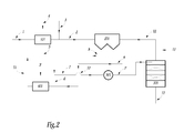
- fumes to be purified 1 are introduced into an evaporator or exchanger / vaporizer 101, which may consist of tubular bundles and which, by heat transfer, generates water vapor 5 while cooling the fumes, which is favorable the capture of subsequent acid pollutants.
- the fumes having passed through the exchanger 101, which are referenced 2 are introduced into a bag filter 201.
- a neutralization reagent 3 is advantageously introduced into these fumes 2.
- the collected solids 8 are recycled.
- a gas-solids contactor 401 the function of which is to carry out an activation of the recirculated residues, before their reintroduction, via a line 11, into the flow of the fumes 1 and which can therefore be described as reactor of activation.
- the steam produced is normally directed entirely to the contactor 401, as indicated by the vapor stream 6, so as to effect the activation of the residues, except when a regeneration is carried out, in which case part of this vapor is superheated by a unit 501, which may be an electric heating battery, and is used for the regeneration of the catalyst.
- the fumes 12, having passed through the filter 201 are admitted into a catalytic denitrification reactor 301, called SCR.
- Acid neutralization reagents are introduced, via a line 3 or a 3 'line, to the baghouse 201 or the activation reactor 401. It should be noted that these reagents can be introduced only at one point. . These reagents are, for example and without limitation, consisting of slaked lime, quicklime, magnesia or sodium bicarbonate.
- a denitrification reagent which may be, for example, ammonia or urea, is fed through line 15 to the denitrification reactor 301.
- the regeneration of the SCR reactor is carried out by intermittently withdrawing the portion 7 of the steam 5 using a set of valves, not shown, by superheating this steam using the superheater 501 and supplying the reactor denitrification 301 by the stream 7 'obtained, which has been brought to a temperature between 250 and 450 ° C by the superheater 501.
- FIG. 1 is schematically and partially shown a possible arrangement of the denitrification reactor 301.
- This catalytic reactor is fed with the fumes 12 mixed with the denitrification reagent, in order to denitrify them.
- This reactor contains a multilayered catalyst 3001, 3002, etc. Preferably, the fumes pass through the reactor vertical upward or downward vertical, but other orientations, for example horizontal, are possible.
- the nitrogen oxides contained in the flue gases 12 are reacted with the aforementioned reagent, mixed with the flue gases upstream of the reactor 301.
- This catalyst is of a known technology and consists, for example, of plates or of channels. It operates at a service temperature of between 140 ° C. and 300 ° C., preferably between 170 ° C. and 240 ° C.
- the fumes to denitrify 12 are fed to the catalyst by a conduit or a similar member, which defines, immediately upstream of the first layer 3001 of the catalyst, a volumic region V catalyst feed by fumes.
- a segmentation of this volume region V in a plurality of zones, in this case six zones in the example shown in the figure, which are respectively referenced V 1 , V 2 , ... V 6 .
- These zones V 1 to V 6 are provided so that each of them is traversed by a part of the flue gas stream 12: thus, in cross-section to the flow, that is to say in a plane perpendicular to the direction of flow.
- these zones V 1 to V 6 each have a non-zero section, in particular being distributed regularly, for example in a pattern in rows and columns in the figures.
- these zones V 1 to V 6 are respectively associated with portions of the first layer, of the catalyst, referenced 3001 1 to 3001 6 on the figure 1
- these portions 3001 1 to 3001 6 represent, together, the entire first layer 3001 of the catalyst, each including a portion of the inlet surface of this first catalyst layer, as clearly visible on the figure 1 .
- the second layer 3002 of the catalyst that is to say the layer just downstream of the layer 3001 following the flue gas flow in the reactor 301, is defined by portions 3002 1 to 3002 6 , corresponding to the portions 3001 1 to 3001 6 . It is the same for the next layer or layers if the catalytic reactor includes one or more layers other than the layers 3001 and 3002.
- separation means for example plates, preferably dismountable, physically provide the internal zoning of the catalytic reactor 301.
- a first set of plates 320 represented only in part for reasons of visibility, provides zoning of the first layer 3001, being arranged in the volume region V so as to delimit the aforementioned zones V 1 to V 6
- a second set of plates 330 shown only in part, provides for the zoning of the second layer 3002 of the catalyst, being arranged in the flue gas supply volume of this second layer 3002, this volume extending from the exit of the first layer to the second layer of the catalyst, so as to delimit zones similar to the zones V 1 to V 6 in the region V.
- the zoning is extended by a catalyst layer to the other by other means, such as sets of plates similar to 320 or 330.
- the different zones of the respective supply volumes of the various layers 3001 and 3002 of the catalyst, as well as the portions of these layers which are respectively associated with them, are distributed in a single row.
- denitrification reactor segmentation 301 is internal, and that one or other part of the reactor is not isolated by registers or valves. The totality of the fumes crosses, permanently, the totality of the catalyst, even when one regenerates a part of it.
- the temperature of the supply of superheated water vapor 7 ' which advantageously has a value between 250 ° C. and 450 ° C., is greater than that of the fumes 12 admitted. in the catalyst of the SCR 301 reactor.
- the water vapor 7 ' has the function of regenerating the catalyst by an essentially thermal action. Under the action of this steam 7 ', the part of the catalyst which is subjected to the action of steam is heated beyond its normal operating temperature. Incidentally and advantageously, this water vapor 7 ' also induces a mechanical action on the catalyst, by blowing dust deposited on this catalyst.
- the superheated steam 7 ' is distributed by distribution means which comprise, inter alia, the output elements of this fluid: in the embodiment considered on the figure 1 these output elements are twelve in number and are referenced, in groups of two copies, 310 1 to 310 6 .
- These output elements 310 1 to 310 6 are located upstream of the first catalyst layer 3001, being distributed in the zones V 1 to V 6 of the region V supply of this layer 3001 fumes. More precisely, in the example shown in the figure, the two output elements 310 1 are in the area V 1 , the two output elements 310 2 are in the area V 2 , and so on. It is of course possible to have a number of output elements different from two per zone of the volume V, for example of one or more than two.
- the output elements 310 1 to 310 6 individually consist of nozzles for delivering the superheated steam 7 '.
- each of these output elements consists of a single pipe, pierced with a terminal orifice.
- the installation comprises means for controlling the supply of the aforementioned dispensing means by superheated steam 7 '.
- these control means are constituted by a set of valves 311 1 to 311 6 which are respectively associated with the output elements 310 1 to 310 6 .
- the supply of the two output elements 310 1 is controlled by the same valve 311 1 , and it is the same for the other output elements.
- a valve can be used to control the supply of each of the two output elements 310 1 , both valves thus associated with these elements 310 1 being jointly controlled.
- valves 311 1 to 311 6 are designed to be driven independently of each other, that is, the opening of the associated valve (s) can be selectively controlled. to the output elements located in one of the zones V 1 to V 6 , while all the other valves of the installation are closed. It is therefore understood that at least one valve is associated per zone segmented volume V, but more than one valve can exist per zone.
- the valves 311 1 to 311 6 are successively opened while all the other valves remain closed, which has the effect of admitting the superheated water vapor 7 'in the distribution means to the output elements 310 1 to 310 6 , these output elements being thus active one after the other.
- the different zones V 1 to V 6 of the feed region V, segmented by the set of plates 320, are, successively and one by one, fed by the steam 7 '.
- This water vapor 7 ' due to the zone segmentation by the set of plates 320, thus first warms the portion 3001 of the catalyst layer 3001 and the portion 3002 1 of the catalyst layer 300 2 , as well as that, if necessary, similar portions of additional layers, layer by layer, and once the intake of water vapor in the zone V 1 stops in favor of the zone V 2 , the water vapor 7 ' then warms the portions 3001 2 and 3002 2 of the catalyst layers 3001 and 3002, as well as, if necessary, similar portions of additional layers, layer by layer. It is therefore, for all the catalyst layers, the portions of these catalyst layers, succeeding via zones, in correspondence with each other, feeding volumes of these layers, which are heated and thus regenerated.
- the flow of fumes 12 is not interrupted, nor the admission of the reagents used to reduce the oxides of nitrogen contained in the fumes.
- the entire catalytic reactor remain operational, but also the entire catalyst continues to work on denitrification since all portions of all catalyst layers continue to receive fumes and neutralization reagent at all times.
- the regeneration of the reactor 301 is done online, without requiring a shutdown of the installation and without reduction of capacity.
- the temperature of the inlet surface of the catalyst is greater than 220 ° C. in its zone during regeneration, preferably greater than 250 ° C. It is understood that obtaining this temperature depends directly on the temperature of the gaseous mixture just above the catalyst. As a result, the ratio of the flow rates between the superheated water vapor 7 'and the proportion of the flue gases 12 passing through the zone being regenerated results from the number of zones chosen for segmenting the catalyst feed region V, as well as that of the respective temperatures of the water vapor 7 'and the fumes 12.
- each of the zones V 1 to V 6 has a cross section worth, at the input surface of the catalyst layer 3001, between 0.3 and 5 m 2 , preferably between 0.5 and 1 m 2 .
- segmentation means 320, 330,... Do not necessarily extend downstream to the inlet surface of the catalyst layer concerned and upstream to the height where the distribution means are located or up to the level of the exit surface of the catalyst layer which precedes the conerned layer. Indeed, the catalyst is often installed in metal boxes, and the catalyst surface is a little behind the surface defined by the box.
- these segmentation means advantageously channel at least 80% of the quantity of the water vapor 7 'from the outlet elements 310 1 , 310 2 , 310 3 , 310 4 , 310 5 and 310 6 to the input surface of the associated portion 3001 1 , 3001 2 , 3001 3 , 3001 4 , 3001 5 or 3001 6 of the first layer 3001 of the catalyst, as well as between the layers 3001 and 3002 and, if appropriate, between the additional layers.
- the overall integration of the process has been shown in a flue gas purification plant.
- the fumes to be purified 1 pass through the evaporator 101 whose function is to produce the vapor 5 which will serve both to the activation of the recirculated residues for its fraction 6 and which will serve as a regeneration fluid 7 'for its fraction 7, after overheating.
- the fumes leaving the evaporator 101 are introduced into the gas-solid separator 201, after the reagents necessary for the purification of the fumes have been introduced, via the line 3 or the line 3 '.
- the location of these injection points is not an object of the invention and one or other of these injection points may not exist.
- the fraction 7 of the produced vapor 5 is intermittently sent to the reactor 301 to serve as a regeneration fluid, after having been superheated by the unit 501.
- This unit 501 is a known technology and is for example an electric heating battery. It is important to realize that this fraction 7 is not sent continuously to the reactor 301, but only when the regeneration of this reactor 301 is necessary.
- the extraction of this stream 7 is done by a set of solenoid valves, not shown.
- the figure 3 represents a variant of the process in which the catalytic reactor 301 is located not downstream as on the figure 2 but upstream of the gas-solid separator 201, being noted that, in all cases, the evaporator 101 is upstream of the denitrification reactor 301.
- the fumes to be purified 1 pass through the evaporator 101 and are then introduced in the denitrification catalytic reactor 301.
- the denitrified fumes 13 that come out are then admitted into the gas-solid separator 201 (a bag filter) in order to eliminate acidic pollutants such as HCl and SO 2 .
- a fraction 10, majority, of the collected solids 8 is introduced into a gas-solids contactor 401.
- FIG. 3 presents a case where these solids 11 are reintroduced upstream of the separator 201 and downstream of the reactor 301, but it is quite possible to reintroduce these solids for all or part upstream of the reactor 301, as shown in dotted lines on the figure 3 .
Landscapes
- Engineering & Computer Science (AREA)
- Chemical & Material Sciences (AREA)
- Environmental & Geological Engineering (AREA)
- General Chemical & Material Sciences (AREA)
- Biomedical Technology (AREA)
- Analytical Chemistry (AREA)
- Health & Medical Sciences (AREA)
- Oil, Petroleum & Natural Gas (AREA)
- Chemical Kinetics & Catalysis (AREA)
- Mechanical Engineering (AREA)
- General Engineering & Computer Science (AREA)
- Life Sciences & Earth Sciences (AREA)
- Sustainable Development (AREA)
- Exhaust Gas Treatment By Means Of Catalyst (AREA)
- Filtering Of Dispersed Particles In Gases (AREA)
Applications Claiming Priority (1)
| Application Number | Priority Date | Filing Date | Title |
|---|---|---|---|
| FR1158263A FR2980120B1 (fr) | 2011-09-16 | 2011-09-16 | Procede et installation d'epuration de fumees |
Publications (2)
| Publication Number | Publication Date |
|---|---|
| EP2570177A1 true EP2570177A1 (de) | 2013-03-20 |
| EP2570177B1 EP2570177B1 (de) | 2016-03-09 |
Family
ID=46800135
Family Applications (1)
| Application Number | Title | Priority Date | Filing Date |
|---|---|---|---|
| EP12184522.6A Not-in-force EP2570177B1 (de) | 2011-09-16 | 2012-09-14 | Method and facility for purifying flue gases |
Country Status (5)
| Country | Link |
|---|---|
| EP (1) | EP2570177B1 (de) |
| DK (1) | DK2570177T3 (de) |
| ES (1) | ES2565810T3 (de) |
| FR (1) | FR2980120B1 (de) |
| PL (1) | PL2570177T3 (de) |
Cited By (4)
| Publication number | Priority date | Publication date | Assignee | Title |
|---|---|---|---|---|
| CN106178949A (zh) * | 2016-08-25 | 2016-12-07 | 华电电力科学研究院 | 一种分级混合高效scr脱硝装置 |
| CN107115733A (zh) * | 2017-06-21 | 2017-09-01 | 中钢集团天澄环保科技股份有限公司 | 一种袋式除尘器喷吹清灰及气态药剂注入装置 |
| WO2018055165A1 (en) * | 2016-09-26 | 2018-03-29 | Shell Internationale Research Maatschappij B.V. | Method of regenerating a denox catalyst |
| US10843132B2 (en) | 2016-09-26 | 2020-11-24 | Shell Oil Company | Method of reducing nitrogen oxide compounds |
Citations (5)
| Publication number | Priority date | Publication date | Assignee | Title |
|---|---|---|---|---|
| EP1576999A1 (de) | 2004-03-05 | 2005-09-21 | Lab Sa | Modulare und intergrierte Vorrichtung zur Filtration und katalytischen Entstickung von Rauchgasen, Anlage enthaltend eine derartige Vorrichtung und Verfahren zu ihrer Verwendung |
| EP1676627A1 (de) | 2005-01-04 | 2006-07-05 | Vinci Environnement | DeNOx Verfahren in einem katalytischen Reaktor |
| US20080089822A1 (en) | 2006-06-22 | 2008-04-17 | Ruedi Frey | Regeneration of nt-scr catalysts |
| EP1949956A1 (de) * | 2007-01-24 | 2008-07-30 | Lab Sa | Verfahren und Anlage zur Klärung von Dämpfen, die saure Schadstoffe enthalten |
| WO2010027617A1 (en) * | 2008-09-05 | 2010-03-11 | Alstom Technology Ltd | A method and a device for removing nitrogen oxides and sulphur trioxide from a process gas |
-
2011
- 2011-09-16 FR FR1158263A patent/FR2980120B1/fr not_active Expired - Fee Related
-
2012
- 2012-09-14 PL PL12184522.6T patent/PL2570177T3/pl unknown
- 2012-09-14 DK DK12184522.6T patent/DK2570177T3/en active
- 2012-09-14 ES ES12184522.6T patent/ES2565810T3/es active Active
- 2012-09-14 EP EP12184522.6A patent/EP2570177B1/de not_active Not-in-force
Patent Citations (5)
| Publication number | Priority date | Publication date | Assignee | Title |
|---|---|---|---|---|
| EP1576999A1 (de) | 2004-03-05 | 2005-09-21 | Lab Sa | Modulare und intergrierte Vorrichtung zur Filtration und katalytischen Entstickung von Rauchgasen, Anlage enthaltend eine derartige Vorrichtung und Verfahren zu ihrer Verwendung |
| EP1676627A1 (de) | 2005-01-04 | 2006-07-05 | Vinci Environnement | DeNOx Verfahren in einem katalytischen Reaktor |
| US20080089822A1 (en) | 2006-06-22 | 2008-04-17 | Ruedi Frey | Regeneration of nt-scr catalysts |
| EP1949956A1 (de) * | 2007-01-24 | 2008-07-30 | Lab Sa | Verfahren und Anlage zur Klärung von Dämpfen, die saure Schadstoffe enthalten |
| WO2010027617A1 (en) * | 2008-09-05 | 2010-03-11 | Alstom Technology Ltd | A method and a device for removing nitrogen oxides and sulphur trioxide from a process gas |
Cited By (6)
| Publication number | Priority date | Publication date | Assignee | Title |
|---|---|---|---|---|
| CN106178949A (zh) * | 2016-08-25 | 2016-12-07 | 华电电力科学研究院 | 一种分级混合高效scr脱硝装置 |
| WO2018055165A1 (en) * | 2016-09-26 | 2018-03-29 | Shell Internationale Research Maatschappij B.V. | Method of regenerating a denox catalyst |
| US10843132B2 (en) | 2016-09-26 | 2020-11-24 | Shell Oil Company | Method of reducing nitrogen oxide compounds |
| US11471831B2 (en) | 2016-09-26 | 2022-10-18 | Shell Usa, Inc. | Method of regenerating a deNOx catalyst |
| CN107115733A (zh) * | 2017-06-21 | 2017-09-01 | 中钢集团天澄环保科技股份有限公司 | 一种袋式除尘器喷吹清灰及气态药剂注入装置 |
| CN107115733B (zh) * | 2017-06-21 | 2020-09-18 | 中钢集团天澄环保科技股份有限公司 | 一种袋式除尘器喷吹清灰及气态药剂注入装置 |
Also Published As
| Publication number | Publication date |
|---|---|
| FR2980120A1 (fr) | 2013-03-22 |
| EP2570177B1 (de) | 2016-03-09 |
| DK2570177T3 (en) | 2016-05-02 |
| FR2980120B1 (fr) | 2016-02-05 |
| PL2570177T3 (pl) | 2016-09-30 |
| ES2565810T3 (es) | 2016-04-07 |
Similar Documents
| Publication | Publication Date | Title |
|---|---|---|
| CN102596364B (zh) | 从工艺气体中除去二氧化碳的方法和系统 | |
| US8961913B2 (en) | Apparatus and system for NOx reduction in wet flue gas | |
| US10350543B2 (en) | Gas treatment process and apparatus | |
| EP2570177B1 (de) | Method and facility for purifying flue gases | |
| FR3038525A1 (fr) | Dispositif d'epuration de fumees, integrant un filtre et un catalyseur | |
| EP2486971B1 (de) | Verfahren zur thermischen in situ Regenerierung eines Katalysators zur Abgasentstickung, und Abgasreinigungsanlage zur Umsetzung dieses Verfahrens | |
| TR201809749T4 (tr) | Kuru gaz temizleyicide kararlı hal durumları süresince kuru emici madde enjeksiyonu. | |
| US20200188851A1 (en) | Flue gas denitration system, incinerator, and flue gas denitration method | |
| JP6216259B2 (ja) | Co2回収装置及びco2回収装置のろ過膜装置の洗浄方法 | |
| JP2017528637A (ja) | 粒状物質及び重金属をエンジン排ガスから除去するための方法及びシステム | |
| WO2017098105A1 (fr) | Procédé de traitement des fumées issues d'un four de combustion ou de calcination et installation pour la mise en oeuvre d'un tel procédé | |
| JP7725201B2 (ja) | 二酸化炭素の回収システム | |
| EP3002060A1 (de) | Regenerierungsverfahren und anlage eines strukturierten denitrifikationskatalysators | |
| FR2993479A1 (fr) | Installation et procede de traitement de gaz avec regeneration, pour echangeur interne a la regeneration. | |
| EP0495710B1 (de) | Anlage zur Wärmeerzeugung mit Entschwefelungsvorrichtung durch regenerierbare Absorptionsmittel | |
| EP1576999B1 (de) | Modulare und integrierte Vorrichtung zur Filtration und katalytischen Entstickung von Rauchgasen, Anlage enthaltend eine derartige Vorrichtung und Verfahren zu ihrer Verwendung | |
| EP2823875A1 (de) | Verfahren zur Rauchgasreinigung | |
| EP2742990A1 (de) | Anlage und Verfahren zur Gasaufbereitung mit Regeneration und Recycling des aus dem Regenerationsprozess hervorgehenden Gases | |
| CA2065599C (fr) | Procede et dispositif de traitement des effluents gazeux issus d'une unite de craquage catalytique | |
| EP1286765A1 (de) | Verfahren und vorrichtung zum regenerieren von verbrauchten sorbentien, die bei der behandlung von rauchgasen aus wärmeerzeuger anfallen | |
| EP1716910A2 (de) | Verfahren und Anlage zur Reinigung von saure Verungreinigungen enthaltenden Rauchgasen | |
| EP0649674B1 (de) | Verfahren und Vorrichtung zur Wärmeerzeugung mit Adsorbensregenierung und Düngemittelherstellung | |
| EP2719444B1 (de) | Katalytisches Denitrifikationsverfahren für Verbrennungsabgase | |
| JP2015213894A (ja) | 脱硫装置及びガス処理システム、並びに、脱硫方法及びガス処理方法 | |
| EP2371444B1 (de) | Verfahren und Anlage zur Reinigung von sauren Verunreinigungen enthaltenden Rauchgasen |
Legal Events
| Date | Code | Title | Description |
|---|---|---|---|
| PUAI | Public reference made under article 153(3) epc to a published international application that has entered the european phase |
Free format text: ORIGINAL CODE: 0009012 |
|
| AK | Designated contracting states |
Kind code of ref document: A1 Designated state(s): AL AT BE BG CH CY CZ DE DK EE ES FI FR GB GR HR HU IE IS IT LI LT LU LV MC MK MT NL NO PL PT RO RS SE SI SK SM TR |
|
| AX | Request for extension of the european patent |
Extension state: BA ME |
|
| 17P | Request for examination filed |
Effective date: 20130805 |
|
| RBV | Designated contracting states (corrected) |
Designated state(s): AL AT BE BG CH CY CZ DE DK EE ES FI FR GB GR HR HU IE IS IT LI LT LU LV MC MK MT NL NO PL PT RO RS SE SI SK SM TR |
|
| RAP1 | Party data changed (applicant data changed or rights of an application transferred) |
Owner name: LAB SA |
|
| GRAP | Despatch of communication of intention to grant a patent |
Free format text: ORIGINAL CODE: EPIDOSNIGR1 |
|
| RIC1 | Information provided on ipc code assigned before grant |
Ipc: B01D 53/86 20060101AFI20150904BHEP Ipc: B01D 53/96 20060101ALI20150904BHEP Ipc: F23J 15/02 20060101ALI20150904BHEP Ipc: B01D 53/50 20060101ALI20150904BHEP |
|
| INTG | Intention to grant announced |
Effective date: 20150930 |
|
| GRAS | Grant fee paid |
Free format text: ORIGINAL CODE: EPIDOSNIGR3 |
|
| GRAA | (expected) grant |
Free format text: ORIGINAL CODE: 0009210 |
|
| AK | Designated contracting states |
Kind code of ref document: B1 Designated state(s): AL AT BE BG CH CY CZ DE DK EE ES FI FR GB GR HR HU IE IS IT LI LT LU LV MC MK MT NL NO PL PT RO RS SE SI SK SM TR |
|
| REG | Reference to a national code |
Ref country code: GB Ref legal event code: FG4D Free format text: NOT ENGLISH |
|
| REG | Reference to a national code |
Ref country code: AT Ref legal event code: REF Ref document number: 779076 Country of ref document: AT Kind code of ref document: T Effective date: 20160315 Ref country code: CH Ref legal event code: EP |
|
| REG | Reference to a national code |
Ref country code: IE Ref legal event code: FG4D Free format text: LANGUAGE OF EP DOCUMENT: FRENCH |
|
| REG | Reference to a national code |
Ref country code: ES Ref legal event code: FG2A Ref document number: 2565810 Country of ref document: ES Kind code of ref document: T3 Effective date: 20160407 |
|
| REG | Reference to a national code |
Ref country code: PT Ref legal event code: SC4A Free format text: AVAILABILITY OF NATIONAL TRANSLATION Effective date: 20160406 |
|
| REG | Reference to a national code |
Ref country code: DE Ref legal event code: R096 Ref document number: 602012015356 Country of ref document: DE |
|
| REG | Reference to a national code |
Ref country code: DK Ref legal event code: T3 Effective date: 20160425 |
|
| REG | Reference to a national code |
Ref country code: NL Ref legal event code: FP |
|
| REG | Reference to a national code |
Ref country code: SE Ref legal event code: TRGR |
|
| REG | Reference to a national code |
Ref country code: LT Ref legal event code: MG4D |
|
| PG25 | Lapsed in a contracting state [announced via postgrant information from national office to epo] |
Ref country code: GR Free format text: LAPSE BECAUSE OF FAILURE TO SUBMIT A TRANSLATION OF THE DESCRIPTION OR TO PAY THE FEE WITHIN THE PRESCRIBED TIME-LIMIT Effective date: 20160610 Ref country code: NO Free format text: LAPSE BECAUSE OF FAILURE TO SUBMIT A TRANSLATION OF THE DESCRIPTION OR TO PAY THE FEE WITHIN THE PRESCRIBED TIME-LIMIT Effective date: 20160609 Ref country code: FI Free format text: LAPSE BECAUSE OF FAILURE TO SUBMIT A TRANSLATION OF THE DESCRIPTION OR TO PAY THE FEE WITHIN THE PRESCRIBED TIME-LIMIT Effective date: 20160309 Ref country code: HR Free format text: LAPSE BECAUSE OF FAILURE TO SUBMIT A TRANSLATION OF THE DESCRIPTION OR TO PAY THE FEE WITHIN THE PRESCRIBED TIME-LIMIT Effective date: 20160309 |
|
| REG | Reference to a national code |
Ref country code: AT Ref legal event code: MK05 Ref document number: 779076 Country of ref document: AT Kind code of ref document: T Effective date: 20160309 |
|
| PG25 | Lapsed in a contracting state [announced via postgrant information from national office to epo] |
Ref country code: LT Free format text: LAPSE BECAUSE OF FAILURE TO SUBMIT A TRANSLATION OF THE DESCRIPTION OR TO PAY THE FEE WITHIN THE PRESCRIBED TIME-LIMIT Effective date: 20160309 Ref country code: LV Free format text: LAPSE BECAUSE OF FAILURE TO SUBMIT A TRANSLATION OF THE DESCRIPTION OR TO PAY THE FEE WITHIN THE PRESCRIBED TIME-LIMIT Effective date: 20160309 Ref country code: RS Free format text: LAPSE BECAUSE OF FAILURE TO SUBMIT A TRANSLATION OF THE DESCRIPTION OR TO PAY THE FEE WITHIN THE PRESCRIBED TIME-LIMIT Effective date: 20160309 |
|
| REG | Reference to a national code |
Ref country code: FR Ref legal event code: PLFP Year of fee payment: 5 |
|
| PG25 | Lapsed in a contracting state [announced via postgrant information from national office to epo] |
Ref country code: IS Free format text: LAPSE BECAUSE OF FAILURE TO SUBMIT A TRANSLATION OF THE DESCRIPTION OR TO PAY THE FEE WITHIN THE PRESCRIBED TIME-LIMIT Effective date: 20160709 Ref country code: EE Free format text: LAPSE BECAUSE OF FAILURE TO SUBMIT A TRANSLATION OF THE DESCRIPTION OR TO PAY THE FEE WITHIN THE PRESCRIBED TIME-LIMIT Effective date: 20160309 |
|
| PG25 | Lapsed in a contracting state [announced via postgrant information from national office to epo] |
Ref country code: SM Free format text: LAPSE BECAUSE OF FAILURE TO SUBMIT A TRANSLATION OF THE DESCRIPTION OR TO PAY THE FEE WITHIN THE PRESCRIBED TIME-LIMIT Effective date: 20160309 Ref country code: SK Free format text: LAPSE BECAUSE OF FAILURE TO SUBMIT A TRANSLATION OF THE DESCRIPTION OR TO PAY THE FEE WITHIN THE PRESCRIBED TIME-LIMIT Effective date: 20160309 Ref country code: RO Free format text: LAPSE BECAUSE OF FAILURE TO SUBMIT A TRANSLATION OF THE DESCRIPTION OR TO PAY THE FEE WITHIN THE PRESCRIBED TIME-LIMIT Effective date: 20160309 Ref country code: AT Free format text: LAPSE BECAUSE OF FAILURE TO SUBMIT A TRANSLATION OF THE DESCRIPTION OR TO PAY THE FEE WITHIN THE PRESCRIBED TIME-LIMIT Effective date: 20160309 |
|
| REG | Reference to a national code |
Ref country code: DE Ref legal event code: R097 Ref document number: 602012015356 Country of ref document: DE |
|
| PLBE | No opposition filed within time limit |
Free format text: ORIGINAL CODE: 0009261 |
|
| STAA | Information on the status of an ep patent application or granted ep patent |
Free format text: STATUS: NO OPPOSITION FILED WITHIN TIME LIMIT |
|
| 26N | No opposition filed |
Effective date: 20161212 |
|
| PG25 | Lapsed in a contracting state [announced via postgrant information from national office to epo] |
Ref country code: BG Free format text: LAPSE BECAUSE OF FAILURE TO SUBMIT A TRANSLATION OF THE DESCRIPTION OR TO PAY THE FEE WITHIN THE PRESCRIBED TIME-LIMIT Effective date: 20160609 |
|
| PG25 | Lapsed in a contracting state [announced via postgrant information from national office to epo] |
Ref country code: MC Free format text: LAPSE BECAUSE OF FAILURE TO SUBMIT A TRANSLATION OF THE DESCRIPTION OR TO PAY THE FEE WITHIN THE PRESCRIBED TIME-LIMIT Effective date: 20160309 |
|
| PG25 | Lapsed in a contracting state [announced via postgrant information from national office to epo] |
Ref country code: SI Free format text: LAPSE BECAUSE OF FAILURE TO SUBMIT A TRANSLATION OF THE DESCRIPTION OR TO PAY THE FEE WITHIN THE PRESCRIBED TIME-LIMIT Effective date: 20160309 |
|
| REG | Reference to a national code |
Ref country code: IE Ref legal event code: MM4A |
|
| PG25 | Lapsed in a contracting state [announced via postgrant information from national office to epo] |
Ref country code: IE Free format text: LAPSE BECAUSE OF NON-PAYMENT OF DUE FEES Effective date: 20160914 |
|
| REG | Reference to a national code |
Ref country code: FR Ref legal event code: PLFP Year of fee payment: 6 |
|
| PG25 | Lapsed in a contracting state [announced via postgrant information from national office to epo] |
Ref country code: LU Free format text: LAPSE BECAUSE OF NON-PAYMENT OF DUE FEES Effective date: 20160914 |
|
| PG25 | Lapsed in a contracting state [announced via postgrant information from national office to epo] |
Ref country code: CY Free format text: LAPSE BECAUSE OF FAILURE TO SUBMIT A TRANSLATION OF THE DESCRIPTION OR TO PAY THE FEE WITHIN THE PRESCRIBED TIME-LIMIT Effective date: 20160309 Ref country code: HU Free format text: LAPSE BECAUSE OF FAILURE TO SUBMIT A TRANSLATION OF THE DESCRIPTION OR TO PAY THE FEE WITHIN THE PRESCRIBED TIME-LIMIT; INVALID AB INITIO Effective date: 20120914 |
|
| PG25 | Lapsed in a contracting state [announced via postgrant information from national office to epo] |
Ref country code: TR Free format text: LAPSE BECAUSE OF FAILURE TO SUBMIT A TRANSLATION OF THE DESCRIPTION OR TO PAY THE FEE WITHIN THE PRESCRIBED TIME-LIMIT Effective date: 20160309 Ref country code: MT Free format text: LAPSE BECAUSE OF FAILURE TO SUBMIT A TRANSLATION OF THE DESCRIPTION OR TO PAY THE FEE WITHIN THE PRESCRIBED TIME-LIMIT Effective date: 20160309 Ref country code: MK Free format text: LAPSE BECAUSE OF FAILURE TO SUBMIT A TRANSLATION OF THE DESCRIPTION OR TO PAY THE FEE WITHIN THE PRESCRIBED TIME-LIMIT Effective date: 20160309 |
|
| REG | Reference to a national code |
Ref country code: FR Ref legal event code: PLFP Year of fee payment: 7 |
|
| PG25 | Lapsed in a contracting state [announced via postgrant information from national office to epo] |
Ref country code: AL Free format text: LAPSE BECAUSE OF FAILURE TO SUBMIT A TRANSLATION OF THE DESCRIPTION OR TO PAY THE FEE WITHIN THE PRESCRIBED TIME-LIMIT Effective date: 20160309 |
|
| PGFP | Annual fee paid to national office [announced via postgrant information from national office to epo] |
Ref country code: FR Payment date: 20180824 Year of fee payment: 7 Ref country code: DE Payment date: 20180913 Year of fee payment: 7 Ref country code: NL Payment date: 20180814 Year of fee payment: 7 Ref country code: IT Payment date: 20180911 Year of fee payment: 7 |
|
| PGFP | Annual fee paid to national office [announced via postgrant information from national office to epo] |
Ref country code: DK Payment date: 20180824 Year of fee payment: 7 Ref country code: CH Payment date: 20180921 Year of fee payment: 7 Ref country code: BE Payment date: 20180924 Year of fee payment: 7 Ref country code: GB Payment date: 20180919 Year of fee payment: 7 Ref country code: SE Payment date: 20180917 Year of fee payment: 7 Ref country code: CZ Payment date: 20180820 Year of fee payment: 7 Ref country code: PL Payment date: 20180817 Year of fee payment: 7 |
|
| PGFP | Annual fee paid to national office [announced via postgrant information from national office to epo] |
Ref country code: PT Payment date: 20180817 Year of fee payment: 7 |
|
| PGFP | Annual fee paid to national office [announced via postgrant information from national office to epo] |
Ref country code: ES Payment date: 20181023 Year of fee payment: 7 |
|
| REG | Reference to a national code |
Ref country code: DE Ref legal event code: R119 Ref document number: 602012015356 Country of ref document: DE |
|
| REG | Reference to a national code |
Ref country code: DK Ref legal event code: EBP Effective date: 20190930 |
|
| PG25 | Lapsed in a contracting state [announced via postgrant information from national office to epo] |
Ref country code: SE Free format text: LAPSE BECAUSE OF NON-PAYMENT OF DUE FEES Effective date: 20190915 |
|
| REG | Reference to a national code |
Ref country code: SE Ref legal event code: EUG |
|
| REG | Reference to a national code |
Ref country code: NL Ref legal event code: MM Effective date: 20191001 |
|
| PG25 | Lapsed in a contracting state [announced via postgrant information from national office to epo] |
Ref country code: CZ Free format text: LAPSE BECAUSE OF NON-PAYMENT OF DUE FEES Effective date: 20190914 |
|
| REG | Reference to a national code |
Ref country code: CH Ref legal event code: PL |
|
| PG25 | Lapsed in a contracting state [announced via postgrant information from national office to epo] |
Ref country code: LI Free format text: LAPSE BECAUSE OF NON-PAYMENT OF DUE FEES Effective date: 20190930 Ref country code: CH Free format text: LAPSE BECAUSE OF NON-PAYMENT OF DUE FEES Effective date: 20190930 Ref country code: PT Free format text: LAPSE BECAUSE OF NON-PAYMENT OF DUE FEES Effective date: 20200422 Ref country code: DE Free format text: LAPSE BECAUSE OF NON-PAYMENT OF DUE FEES Effective date: 20200401 Ref country code: NL Free format text: LAPSE BECAUSE OF NON-PAYMENT OF DUE FEES Effective date: 20191001 |
|
| REG | Reference to a national code |
Ref country code: BE Ref legal event code: MM Effective date: 20190930 |
|
| PG25 | Lapsed in a contracting state [announced via postgrant information from national office to epo] |
Ref country code: BE Free format text: LAPSE BECAUSE OF NON-PAYMENT OF DUE FEES Effective date: 20190930 Ref country code: IT Free format text: LAPSE BECAUSE OF NON-PAYMENT OF DUE FEES Effective date: 20190914 |
|
| GBPC | Gb: european patent ceased through non-payment of renewal fee |
Effective date: 20190914 |
|
| PG25 | Lapsed in a contracting state [announced via postgrant information from national office to epo] |
Ref country code: FR Free format text: LAPSE BECAUSE OF NON-PAYMENT OF DUE FEES Effective date: 20190930 Ref country code: DK Free format text: LAPSE BECAUSE OF NON-PAYMENT OF DUE FEES Effective date: 20190930 Ref country code: GB Free format text: LAPSE BECAUSE OF NON-PAYMENT OF DUE FEES Effective date: 20190914 |
|
| REG | Reference to a national code |
Ref country code: ES Ref legal event code: FD2A Effective date: 20210128 |
|
| PG25 | Lapsed in a contracting state [announced via postgrant information from national office to epo] |
Ref country code: ES Free format text: LAPSE BECAUSE OF NON-PAYMENT OF DUE FEES Effective date: 20190915 |
|
| PG25 | Lapsed in a contracting state [announced via postgrant information from national office to epo] |
Ref country code: PL Free format text: LAPSE BECAUSE OF NON-PAYMENT OF DUE FEES Effective date: 20190914 |