EP2570178B1 - Dispositif de mélange - Google Patents
Dispositif de mélange Download PDFInfo
- Publication number
- EP2570178B1 EP2570178B1 EP12405103.8A EP12405103A EP2570178B1 EP 2570178 B1 EP2570178 B1 EP 2570178B1 EP 12405103 A EP12405103 A EP 12405103A EP 2570178 B1 EP2570178 B1 EP 2570178B1
- Authority
- EP
- European Patent Office
- Prior art keywords
- mixing device
- sub
- section
- exhaust gas
- channels
- Prior art date
- Legal status (The legal status is an assumption and is not a legal conclusion. Google has not performed a legal analysis and makes no representation as to the accuracy of the status listed.)
- Active
Links
Images




Classifications
-
- B—PERFORMING OPERATIONS; TRANSPORTING
- B01—PHYSICAL OR CHEMICAL PROCESSES OR APPARATUS IN GENERAL
- B01D—SEPARATION
- B01D53/00—Separation of gases or vapours; Recovering vapours of volatile solvents from gases; Chemical or biological purification of waste gases, e.g. engine exhaust gases, smoke, fumes, flue gases, aerosols
- B01D53/34—Chemical or biological purification of waste gases
- B01D53/74—General processes for purification of waste gases; Apparatus or devices specially adapted therefor
- B01D53/86—Catalytic processes
- B01D53/8621—Removing nitrogen compounds
- B01D53/8625—Nitrogen oxides
- B01D53/8631—Processes characterised by a specific device
-
- B—PERFORMING OPERATIONS; TRANSPORTING
- B01—PHYSICAL OR CHEMICAL PROCESSES OR APPARATUS IN GENERAL
- B01D—SEPARATION
- B01D53/00—Separation of gases or vapours; Recovering vapours of volatile solvents from gases; Chemical or biological purification of waste gases, e.g. engine exhaust gases, smoke, fumes, flue gases, aerosols
- B01D53/34—Chemical or biological purification of waste gases
- B01D53/92—Chemical or biological purification of waste gases of engine exhaust gases
- B01D53/94—Chemical or biological purification of waste gases of engine exhaust gases by catalytic processes
- B01D53/9404—Removing only nitrogen compounds
- B01D53/9409—Nitrogen oxides
- B01D53/9431—Processes characterised by a specific device
-
- B—PERFORMING OPERATIONS; TRANSPORTING
- B01—PHYSICAL OR CHEMICAL PROCESSES OR APPARATUS IN GENERAL
- B01F—MIXING, e.g. DISSOLVING, EMULSIFYING OR DISPERSING
- B01F23/00—Mixing according to the phases to be mixed, e.g. dispersing or emulsifying
- B01F23/20—Mixing gases with liquids
- B01F23/21—Mixing gases with liquids by introducing liquids into gaseous media
- B01F23/213—Mixing gases with liquids by introducing liquids into gaseous media by spraying or atomising of the liquids
- B01F23/2132—Mixing gases with liquids by introducing liquids into gaseous media by spraying or atomising of the liquids using nozzles
-
- B—PERFORMING OPERATIONS; TRANSPORTING
- B01—PHYSICAL OR CHEMICAL PROCESSES OR APPARATUS IN GENERAL
- B01F—MIXING, e.g. DISSOLVING, EMULSIFYING OR DISPERSING
- B01F25/00—Flow mixers; Mixers for falling materials, e.g. solid particles
- B01F25/30—Injector mixers
- B01F25/31—Injector mixers in conduits or tubes through which the main component flows
- B01F25/313—Injector mixers in conduits or tubes through which the main component flows wherein additional components are introduced in the centre of the conduit
- B01F25/3131—Injector mixers in conduits or tubes through which the main component flows wherein additional components are introduced in the centre of the conduit with additional mixing means other than injector mixers, e.g. screens, baffles or rotating elements
-
- B—PERFORMING OPERATIONS; TRANSPORTING
- B01—PHYSICAL OR CHEMICAL PROCESSES OR APPARATUS IN GENERAL
- B01F—MIXING, e.g. DISSOLVING, EMULSIFYING OR DISPERSING
- B01F25/00—Flow mixers; Mixers for falling materials, e.g. solid particles
- B01F25/30—Injector mixers
- B01F25/31—Injector mixers in conduits or tubes through which the main component flows
- B01F25/314—Injector mixers in conduits or tubes through which the main component flows wherein additional components are introduced at the circumference of the conduit
- B01F25/3141—Injector mixers in conduits or tubes through which the main component flows wherein additional components are introduced at the circumference of the conduit with additional mixing means other than injector mixers
-
- B—PERFORMING OPERATIONS; TRANSPORTING
- B01—PHYSICAL OR CHEMICAL PROCESSES OR APPARATUS IN GENERAL
- B01F—MIXING, e.g. DISSOLVING, EMULSIFYING OR DISPERSING
- B01F25/00—Flow mixers; Mixers for falling materials, e.g. solid particles
- B01F25/40—Static mixers
- B01F25/42—Static mixers in which the mixing is affected by moving the components jointly in changing directions, e.g. in tubes provided with baffles or obstructions
- B01F25/421—Static mixers in which the mixing is affected by moving the components jointly in changing directions, e.g. in tubes provided with baffles or obstructions by moving the components in a convoluted or labyrinthine path
- B01F25/423—Static mixers in which the mixing is affected by moving the components jointly in changing directions, e.g. in tubes provided with baffles or obstructions by moving the components in a convoluted or labyrinthine path by means of elements placed in the receptacle for moving or guiding the components
- B01F25/4231—Static mixers in which the mixing is affected by moving the components jointly in changing directions, e.g. in tubes provided with baffles or obstructions by moving the components in a convoluted or labyrinthine path by means of elements placed in the receptacle for moving or guiding the components using baffles
-
- B—PERFORMING OPERATIONS; TRANSPORTING
- B01—PHYSICAL OR CHEMICAL PROCESSES OR APPARATUS IN GENERAL
- B01F—MIXING, e.g. DISSOLVING, EMULSIFYING OR DISPERSING
- B01F25/00—Flow mixers; Mixers for falling materials, e.g. solid particles
- B01F25/40—Static mixers
- B01F25/42—Static mixers in which the mixing is affected by moving the components jointly in changing directions, e.g. in tubes provided with baffles or obstructions
- B01F25/43—Mixing tubes, e.g. wherein the material is moved in a radial or partly reversed direction
- B01F25/431—Straight mixing tubes with baffles or obstructions that do not cause substantial pressure drop; Baffles therefor
- B01F25/4313—Straight mixing tubes with baffles or obstructions that do not cause substantial pressure drop; Baffles therefor comprising a plurality of stacked ducts having their axes parallel to the tube axis
-
- F—MECHANICAL ENGINEERING; LIGHTING; HEATING; WEAPONS; BLASTING
- F01—MACHINES OR ENGINES IN GENERAL; ENGINE PLANTS IN GENERAL; STEAM ENGINES
- F01N—GAS-FLOW SILENCERS OR EXHAUST APPARATUS FOR MACHINES OR ENGINES IN GENERAL; GAS-FLOW SILENCERS OR EXHAUST APPARATUS FOR INTERNAL-COMBUSTION ENGINES
- F01N1/00—Silencing apparatus characterised by method of silencing
- F01N1/08—Silencing apparatus characterised by method of silencing by reducing exhaust energy by throttling or whirling
- F01N1/084—Silencing apparatus characterised by method of silencing by reducing exhaust energy by throttling or whirling the exhaust gases flowing through the silencer two or more times longitudinally in opposite directions, e.g. using parallel or concentric tubes
-
- F—MECHANICAL ENGINEERING; LIGHTING; HEATING; WEAPONS; BLASTING
- F01—MACHINES OR ENGINES IN GENERAL; ENGINE PLANTS IN GENERAL; STEAM ENGINES
- F01N—GAS-FLOW SILENCERS OR EXHAUST APPARATUS FOR MACHINES OR ENGINES IN GENERAL; GAS-FLOW SILENCERS OR EXHAUST APPARATUS FOR INTERNAL-COMBUSTION ENGINES
- F01N3/00—Exhaust or silencing apparatus having means for purifying, rendering innocuous, or otherwise treating exhaust
- F01N3/08—Exhaust or silencing apparatus having means for purifying, rendering innocuous, or otherwise treating exhaust for rendering innocuous
- F01N3/10—Exhaust or silencing apparatus having means for purifying, rendering innocuous, or otherwise treating exhaust for rendering innocuous by thermal or catalytic conversion of noxious components of exhaust
- F01N3/18—Exhaust or silencing apparatus having means for purifying, rendering innocuous, or otherwise treating exhaust for rendering innocuous by thermal or catalytic conversion of noxious components of exhaust characterised by methods of operation; Control
- F01N3/20—Exhaust or silencing apparatus having means for purifying, rendering innocuous, or otherwise treating exhaust for rendering innocuous by thermal or catalytic conversion of noxious components of exhaust characterised by methods of operation; Control specially adapted for catalytic conversion
- F01N3/206—Adding periodically or continuously substances to exhaust gases for promoting purification, e.g. catalytic material in liquid form, NOx reducing agents
- F01N3/2066—Selective catalytic reduction [SCR]
-
- F—MECHANICAL ENGINEERING; LIGHTING; HEATING; WEAPONS; BLASTING
- F01—MACHINES OR ENGINES IN GENERAL; ENGINE PLANTS IN GENERAL; STEAM ENGINES
- F01N—GAS-FLOW SILENCERS OR EXHAUST APPARATUS FOR MACHINES OR ENGINES IN GENERAL; GAS-FLOW SILENCERS OR EXHAUST APPARATUS FOR INTERNAL-COMBUSTION ENGINES
- F01N2240/00—Combination or association of two or more different exhaust treating devices, or of at least one such device with an auxiliary device, not covered by indexing codes F01N2230/00 or F01N2250/00, one of the devices being
- F01N2240/20—Combination or association of two or more different exhaust treating devices, or of at least one such device with an auxiliary device, not covered by indexing codes F01N2230/00 or F01N2250/00, one of the devices being a flow director or deflector
-
- F—MECHANICAL ENGINEERING; LIGHTING; HEATING; WEAPONS; BLASTING
- F01—MACHINES OR ENGINES IN GENERAL; ENGINE PLANTS IN GENERAL; STEAM ENGINES
- F01N—GAS-FLOW SILENCERS OR EXHAUST APPARATUS FOR MACHINES OR ENGINES IN GENERAL; GAS-FLOW SILENCERS OR EXHAUST APPARATUS FOR INTERNAL-COMBUSTION ENGINES
- F01N2610/00—Adding substances to exhaust gases
- F01N2610/02—Adding substances to exhaust gases the substance being ammonia or urea
-
- F—MECHANICAL ENGINEERING; LIGHTING; HEATING; WEAPONS; BLASTING
- F01—MACHINES OR ENGINES IN GENERAL; ENGINE PLANTS IN GENERAL; STEAM ENGINES
- F01N—GAS-FLOW SILENCERS OR EXHAUST APPARATUS FOR MACHINES OR ENGINES IN GENERAL; GAS-FLOW SILENCERS OR EXHAUST APPARATUS FOR INTERNAL-COMBUSTION ENGINES
- F01N2610/00—Adding substances to exhaust gases
- F01N2610/14—Arrangements for the supply of substances, e.g. conduits
- F01N2610/1453—Sprayers or atomisers; Arrangement thereof in the exhaust apparatus
-
- Y—GENERAL TAGGING OF NEW TECHNOLOGICAL DEVELOPMENTS; GENERAL TAGGING OF CROSS-SECTIONAL TECHNOLOGIES SPANNING OVER SEVERAL SECTIONS OF THE IPC; TECHNICAL SUBJECTS COVERED BY FORMER USPC CROSS-REFERENCE ART COLLECTIONS [XRACs] AND DIGESTS
- Y02—TECHNOLOGIES OR APPLICATIONS FOR MITIGATION OR ADAPTATION AGAINST CLIMATE CHANGE
- Y02T—CLIMATE CHANGE MITIGATION TECHNOLOGIES RELATED TO TRANSPORTATION
- Y02T10/00—Road transport of goods or passengers
- Y02T10/10—Internal combustion engine [ICE] based vehicles
- Y02T10/12—Improving ICE efficiencies
Definitions
- the invention relates to a mixing device for use in the catalytic removal of nitrogen oxides (NO x ) from an exhaust gas stream and a device consisting of a mixing device and a reactor, wherein in the mixing device, a gaseous or liquid reactant is homogeneously distributed in the exhaust stream, and the exhaust gas stream is then passed through a reactor for the selective catalytic reduction of nitrogen oxides by the SCR process.
- a mixing device for use in the catalytic removal of nitrogen oxides (NO x ) from an exhaust gas stream and a device consisting of a mixing device and a reactor, wherein in the mixing device, a gaseous or liquid reactant is homogeneously distributed in the exhaust stream, and the exhaust gas stream is then passed through a reactor for the selective catalytic reduction of nitrogen oxides by the SCR process.
- static mixers have been used for many years to mix gases or liquids.
- Static mixers are internals in pipes, which cause a stall and thereby generate intense turbulence and cross flows. These internals reduce the necessary mixing distance.
- An overview of static mixers is z. In the Book “Mixing and Stirring” Wiley-VCH Verlag, 2003 given. When mixing in gas streams, the mixing elements are used by degrees.
- Such static mixers are also often used for mixing exhaust gas streams with gaseous or liquid reactants in front of an SCR catalyst, in which a selective catalytic reduction of nitrogen oxides (NO x ) takes place with the addition of a reactive species.
- the exhaust gas may come from an industrial process, a boiler or from a motor source.
- the reactive species in the SCR process is ammonia (NH 3 ). This can be used directly as a gas. However, it is also possible to use a liquid solution of NH 3 or urea (CO (NH 2 ) 2 ) in water (HWL: urea-water solution; AdBlue: 32.5% urea solution in demineralized water) as the reactant.
- HWL urea-water solution
- AdBlue 32.5% urea solution in demineralized water
- the reactive species NH 3 is also formed from the urea by a hydrolysis reaction. The nitrogen oxides are converted to nitrogen and water with the reducing agent NH 3 in the presence of oxygen on the surface of the catalyst.
- the WO 2007/110575 A1 discloses a mixing device for distributing a reactant in the exhaust stream.
- the exhaust gas flows through three concentric sections within the mixing device and is deflected twice.
- perforated plates are provided for generating vortices.
- the perforated plates are relatively long, so that the individual sections are greatly shortened.
- each sub-channel is formed in cross section as a circular ring, the central area of the mixing device is not used.
- a device which comprises a Pyrolisationskanal, a mixing channel and a reaction channel.
- the three channels are eccentric, but only the first two channels are available for mixing, since there are already reduction catalysts in the third channel.
- the mixing takes place in particular in the mixing channel, which has several cross-flow mixer.
- the object of the invention is to provide a device belonging to the aforementioned technical field, which includes a mixing device, with a
- Reactant can be efficiently mixed with the exhaust stream and is compact and so easy to integrate structurally.
- a mixing device for use in the catalytic removal of nitrogen oxides from an exhaust gas stream.
- a gaseous or liquid reactant and the exhaust gases to be cleaned are homogeneously mixed with each other.
- the mixing device is arranged in the flow direction of the exhaust gases in front of a reactor for the catalytic removal of nitrogen oxides by the SCR method.
- the exhaust gas stream is fed to the SCR reactor after flowing through the mixing device.
- the mixing device is a structural element that includes the mixing section.
- the mixing device is designed in such a way that the exhaust gas flow within the mixing device is deflected at least twice by 180 ° in each case at a flow separation edge.
- a mixing section is understood to mean a region in which two substances which arrive separately in the mixing device mix as far as possible homogeneously with one another by flow-related relative movements.
- a reactant is sprayed into an exhaust jet.
- the z. B. is designed as a straight tube, the reaction agent distributed more and more in the exhaust gas jet. But this requires a certain mixing time. This means that the two substances must travel a certain distance in order to be sufficiently mixed with each other, so that the mixing device must be designed to be correspondingly long.
- Guiding plates in the flow cross-section take place, on which deposits of the reaction medium can form. Increasing the internal surface improves the complete evaporation. A stall as a simple component allows efficient turbulence and is not associated with a noticeable pressure loss, which in other installations such. B. perforated plates occurs. In addition, stall edges are cheaper to manufacture than other elements.
- the mixing means for the reactant should always be arranged in front of the SCR reactor in the direction of the exhaust gas flow. Furthermore, it is advantageous if there is no oxidation reactor and / or DPF with oxidizing coating between injection and SCR reactor. Otherwise, the reducing agent NH 3 would be completely or partially oxidized to NO x on these catalyst surfaces before it can come to react on the SCR catalyst.
- a typical exhaust system of a diesel engine consists of an oxidation catalyst (Oxi), a soot filter (DPF), a HWL injection, a mixing device and an SCR reactor.
- the mixing device is dimensioned on the front side, at which the exhaust gas stream exits, such that it has an overall cross-section which is the same size as a total cross-section of the input-side end side of a downstream reactor. Matching cross-sections make it easy to assemble the two elements and save expensive transitions.
- the entire mixing device will have a constant cross-section. But it is also possible that the two end faces are dimensioned differently. This is conceivable, in particular in the case of structural features in the vicinity of the reactor or the mixing device.
- the mixing device and the subsequent reactor are arranged in a common housing. That is, the mixing device exists as a component together with an SCR reactor. This simplifies necessary installations or modifications to exhaust gas lines, since only one and not two components have to be mounted. A necessary transition between mixing device and reactor is eliminated.
- the mixing device is present as a separate component, and thus the mixing device and the subsequent reactor are in separate housings.
- This makes it possible to arrange mixing device and reactor a certain amount of space flexible.
- z. B. lack of space no direct juxtaposition of the two components is possible, they can be attached to each other with a certain distance and / or a certain angle.
- the two housings can be provided with suitable detachable connection mechanisms, so that the mixing device can be detached from the reactor with little effort and fixed on it again.
- the mixing device is divided in its overall longitudinal section into three sub-channels.
- the sub-channels are perpendicular to the outlet direction of the exhaust gas. They are also connected to one another via a deflection point and result in a total mixing section, the length of the three sub-channels and the deflection point, in which the exhaust gas flow is deflected at least twice by 180 °.
- the three sub-channels have the same size flow cross-sections.
- the resulting mixing section thus has a constant diameter, and there are hardly any pressure losses.
- the exhaust gas enters and exits through a much smaller exhaust port compared to the reactor.
- the cross section of the subsequent reactor is always substantially larger than the flow cross section of the mixing section.
- the diameter of the mixing section must, on the other hand, usually be greater than the diameter of the exhaust pipe after the engine. Only in this way can the necessary residence times in the mixing section and in the reactor be achieved with low pressure loss and sufficient flow velocity in the mixing device.
- the cross section of the reactor is preferably about 3 to 5 times larger than the flow cross section of the mixing section.
- the sum of the cross sections of the subchannels preferably corresponds to a reactor cross section.
- the compact mixing device has external dimensions which correspond to those of the possibly upstream (oxidation catalytic converter and DPF) and / or the optionally downstream reactor (DPF / SCR or SCR). Due to the suitable size, they can easily be welded together or connected by common flanges (screws, clamps). In addition, the largest possible subchannels are provided and the space within the mixing device is optimally utilized.
- the mixing device is divided into three subchannels, wherein the subchannels are delimited by eccentrically arranged separating plates.
- the baffles are positioned within the mixing device so that three sub-channels are formed.
- the three sub-channels are connected to a mixing section such that an exhaust gas flow is deflected at least twice by 180 °. A double deflection or deflection improves the mixing compared to only one deflection significantly.
- an eccentric arrangement of the separating plates means the fact that the separating plates, which together with the outer walls of the mixing device define the subchannels, have their own main axes, which do not coincide with the main axis of the mixing device. So you moved out of the center. Eccentric arrangements are suitable for small mixing devices, since in them the reagent can not be added centrally. The typical construction methods do not allow to provide a corresponding nozzle in the center.
- the mixing device is circular in the overall cross section. It is a circle with radius R.
- the mixing device has the same cross-section as the downstream reactor.
- the three subchannels of the mixing device preferably have the same cross section. It is advantageous if the three sub-channels and also the deflection points between the sub-channels have the same cross section, so that the entire mixing section has a constant flow cross-section.
- This flow cross section preferably corresponds to one third of the total cross section of the mixing device.
- a constant flow cross-section prevents pressure losses and thus guarantees constant residence times of the exhaust gas in the mixing device or in the downstream reactor.
- the exhaust gas is sufficiently slowed down that it flows past the catalytically active surfaces of the reactor at the correct rate, so that a reduction of the nitrogen oxides can take place.
- the partitions that define the subchannels are bent in profile so that they have a circular arc profile.
- they have a radius of curvature r, which is equal to the radius R of the total cross section of the mixing device. Their radius thus corresponds to the radius of the housing.
- This coincident curvature facilitates the construction of a mixing device with three sub-channels, these having a constant cross-section.
- the bent dividers each correspond to a circular arc of the mixing device.
- the center Z the mixing device lies on the main axis.
- the centers Z1 and Z2 of the bent dividers are displaced from the center Z of the mixing device.
- the total cross-section is divided into three equal parts.
- the pointing in the deflection of edges of the curved dividers may be straight. Then, a mixing device with the same flow cross-section in the sub-channels and also in the deflection between the sub-channels can be particularly easily constructed.
- the bent dividers have recesses at the edges in the deflection points.
- the flow cross section is changed at this point, so that the flow cross sections in the region of the deflection points are larger than the flow cross sections in the subchannels.
- additional turbulences are generated which increase the degree of mixing.
- the mixing device is divided into three sub-channels, wherein the sub-channels are arranged concentrically. This means that the sub-channels are arranged around a common main axis, but have different diameters.
- the sub-channels are connected to each other via deflection points, so that a mixing section is formed, in which an exhaust gas flow is deflected at least twice by 180 °. A double deflection of the exhaust gas stream allows a good mixing with the reagent.
- a concentric design of the subchannels expands the possibilities of positioning nozzles for the reactant in the mixing device.
- the mixing devices can be operated in such a way that an exhaust gas flow is conducted from the outside to the inside. This means that first of all the outermost sub-channel with the largest diameter flows through, and the exhaust gas from the innermost sub-channel with the smallest diameter leaves the mixing device.
- a plurality of nozzles may be provided in the outermost channel.
- a plurality of nozzles are positioned at the beginning of the outermost first sub-channel, whose cross section corresponds to a circular ring.
- the best mixing is achieved when the nozzles are arranged as symmetrically as possible in a cross section of the annulus, d. H. in the first subchannel occupy the same distance to the inlet region of the exhaust gas and are distributed over the entire circumference with the greatest possible distance from each other.
- an arrangement opposite one another is advantageously selected. As the number of nozzles increases, the distances between the nozzles decrease.
- the exhaust gas can also flow inversely through the concentric mixing device, d. H. from the inside to the outside. It enters the innermost sub-channel with the smallest diameter and leaves the mixing device through the outer sub-channel with the largest diameter.
- a nozzle for spraying the reagent can be provided centrally in the inner part of the channel.
- an additional spray funnel may be provided on the nozzle, which improves the mixing of the reaction agent with the exhaust gas.
- the sub-channels of a concentric mixing device may be formed circular in cross-section and then correspond to a structure of a central circle and several, ever larger circular rings.
- the cross section of the sub-channels may also be square, elliptical or arbitrary.
- even angular systems are mechanically less stable and can easily get into vibration due to the exhaust fumes flowing through them, as a result of which the stability is somewhat reduced and, if necessary, also secondary noise occurs.
- the sub-channels of a mixing device can also have different shapes in cross-section, they should only have a common center of gravity or a common main axis.
- the central inner part of the channel is designed as a circular cylinder and thus has a constant cross section in its length. This will ensure that the Flow cross-section remains constant and thus the smallest possible pressure losses occur within the mixing device. As a result, the flow rate of the exhaust gas reaction mixture is kept as constant as possible. This is an advantage over conical sub-channels or systems having the internals in the mixing section.
- the three sub-channels have the same flow cross-section. It is particularly advantageous if the three sub-channels and also the deflection points between the sub-channels have the same flow cross-section, so that the entire mixing section has a constant flow cross-section.
- This flow cross section preferably corresponds to one third of the total cross section of the mixing device.
- the constant flow cross-section minimizes pressure losses, so that constant residence times of the exhaust gas in the mixing device or in the downstream reactor can be adjusted.
- the diameter widens to three times, ie to the diameter of the subsequent reactor. As a result, the exhaust gas is slowed down and can flow past the catalytically active surfaces of the reactor at the slower rate, where reduction of the nitrogen oxides takes place.
- a concentric mixing section corresponds to cylinders lying inside one another, which have a smaller diameter from the outside to the inside.
- the exhaust gas is deflected around an edge of a cylinder.
- This edge may be formed as a continuous, continuous edge.
- the mixing device can be easily constructed so that the sub-channels and also the deflection points between the sub-channels have the same flow cross-section.
- recesses are provided in the region of the edges in the deflection.
- the flow cross section is changed at this point, so that the flow cross sections in the region of the deflection points are larger than the flow cross sections in the subchannels.
- additional turbulences are generated which increase the degree of mixing.
- an edge has a recess, it is optionally possible to set a continuously constant flow cross section by adjusting the length of the entire cylinder.
- At least one metering point for a liquid or gaseous reactant is arranged in at least one first part-channel.
- the reactant is added as possible when the exhaust gas enters the mixing device, so that the maximum distance for mixing is available.
- the metering point is already arranged in front of the mixing device, which offers more possibilities in the construction of a corresponding mixing device.
- it then requires a precise coordination between metering and mixing device, since the size ratios must be adjusted.
- the metering can be located in a sub-channel, which is later flowed through by the exhaust gas.
- it is no longer possible to use the complete mixing section of the mixing device. This should be done only with sufficiently long mixing distances, otherwise deposits of the reaction agent within the mixing device arise.
- the exhaust gas-solvent mixture has a sufficiently long time, so that the droplets of the solution can evaporate before the mixture reaches the first deflection point.
- the minimum length of a first section depends on the droplet size of the reaction medium, which is added to the exhaust gas. Although many other parameters can be adjusted, droplet size is the factor that can not readily be adjusted. Therefore, a minimum distance is required within which the reaction agent is to evaporate and does not deposit at the deflection point.
- the metering point is provided within the mixing device such that the mixture can first travel as long as possible.
- additional guide elements and / or static mixers are provided in the sub-channels and / or at the deflection points. These additional fittings create more turbulence and thus improve the mixing.
- static mixers are preferably used at the end of the last sub-channel, since they are accessible from the outside.
- Perforated metal sheets may also be provided at the end of the mixing device, in particular at the end of the mixing device, that is to say when the exhaust gas-reagent mixture is transferred to the downstream reactor.
- a perforated plate is preferably installed at an angle when passing into the downstream reactor.
- An improved mixing of the exhaust gas with the reagent can be achieved by means of a spray funnel in front of a metering device.
- the metering device is located centrally in the inner subchannel.
- the spray funnel has the shape of a truncated cone whose top surface is closed and the base surface is open. It points with the closed top surface in the direction of the incoming exhaust gas, while the metering device is in the region of the open base.
- recesses are provided on the dividing plates in the region of the deflection points.
- the geometry of the stall edge is changed, which leads to additional turbulence and thus improves the mixing.
- the flow cross-section in the deflection is increased, which is compensated if necessary by adjusting the length of the separating plate.
- the inlet for the exhaust gas stream is arranged axially in the mixing device.
- Such mixing devices can be installed particularly easily in linearly arranged exhaust gas strands.
- the exhaust gas flow may be advantageous if the exhaust gas flow enters radially (or transversely to the axis of the output from the mixing device) in the mixing device. Under certain circumstances, special angles for custom made may be necessary.
- a mixing device as a separate device of a reactor is the subject of the invention. According to the invention, this is suitable for use in the catalytic removal of nitrogen oxides from an exhaust gas stream, wherein in the mixing device, a gaseous or liquid reactant is homogeneously distributed in the exhaust stream, and the exhaust gas stream thereafter a (separate) reactor for the catalytic removal of nitrogen oxides after the SCR Method is supplied.
- a gaseous or liquid reactant is homogeneously distributed in the exhaust stream, and the exhaust gas stream thereafter a (separate) reactor for the catalytic removal of nitrogen oxides after the SCR Method is supplied.
- a (separate) reactor for the catalytic removal of nitrogen oxides after the SCR Method is supplied.
- at least one deflection point is provided with a flow separation edge, at which the exhaust gas flow is deflected.
- this mixing device can be equipped with the features of the overall device described above as being preferred.
- a first partial channel of the mixing device preferably has a constant cross section in the region between a metering point and a first deflection.
- the first subchannel that is to say the subchannel which is first flowed through by the exhaust gas, is the inner or outer subchannel of a concentrically constructed mixing device. These are preferably circular or annular in cross section. But it may also be a first sub-channel of an eccentric mixing device.
- a constant cross section in the first subchannel minimizes pressure changes in the system so that a continuous flow of the exhaust gas reactant mixture can take place.
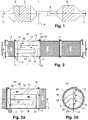
- Fig. 1 shows a typical exhaust line 1 of a diesel engine.
- the exhaust gas from the engine flows from left to right first through an oxidation catalyst 2 and then through a diesel particulate filter 3. Subsequently, the reactant is added through a HWL nozzle 4 and the exhaust gas is mixed with the reactant in the mixer 5 before passing the SCR reactor 6 happened.
- the mixer 5 is arranged directly in front of the SCR reactor 6 and is designed as a mixing tube.
- Such an exhaust line 1 for mobile purposes (cars, trucks, construction machinery, etc.) has only limited space, so that the systems are hardly integrated within the available space. In particular, the mixer 5 is relatively short.
- Fig. 2 shows a longitudinal section through a first inventive embodiment of the mixing device 10 for a round DPF / SCR reactor 11 with an upstream reactor for receiving an oxidation catalyst 12.
- the mixing device 10 includes three sub-channels 13, 14, 15 with the same cross section, which are arranged eccentrically , The sub-channels 13, 14, 15 and the deflection points 8a, b connecting them are defined via the side plates 16, 17 and over the bent dividing plates 18, 19.
- the reactant is introduced at the beginning of the sub-channel 13, which the exhaust gas passes first HWL nozzle 4 supplied.
- the length L of the mixing device 10 depends on a liquid reactant according to the requirements of the evaporation and Mixture.
- the length L of the mixing device 10 should correspond to two to three times the greatest vertical distance of the separating plates from one another or from the housing wall, since in this way the vortices are optimally utilized.
- the sum of the sub-channels 13, 14, 15 and the deflection points 8 a, b yields the mixing section 25.
- Fig. 3a, b show an enlarged section of the mixing device 10 in the longitudinal or cross section.
- the subdivision of the mixing device 10 is achieved in particular by two curved separating plates 18, 19.
- the bending radius R of the two bent dividers 18, 19 corresponds to the bending radius of the housing shell 20.
- the centers Z1 and Z2 of the bent dividers 18, 19 are offset from the center Z of the reactor with the cross section A, that three equal in cross section sub-channels 13, 14, 15 are formed with the cross section A / 3.
- the reactant is fed to the exhaust gas stream via the nozzle 4 finely atomized.
- the mixture is then deflected after passing through the first sub-channel 13 by 180 ° in the sub-channel 14 and then flows against the flow direction. Subsequently, the mixture is deflected by 180 ° in sub-channel 15 and thus again in the flow direction. The mixture then impinges from the sub-channel 15 on the downstream SCR reactor.
- the side plate 16 On the inlet side, the interior of the mixing device 10 is closed at the end by the side plate 16.
- the side plate 16 has a crescent-shaped opening, which releases the entry into sub-channel 13. Conversely, the conclusion takes place on the outlet side by a corresponding side plate 17, which releases a crescent-shaped opening for the exit from the partial channel 15.
- the pressure loss and the distance to the outlet from the mixing device should be sufficiently large to ensure a good pressure equalization and thus a homogeneous flow rate distribution in the downstream SCR reactor. If the pressure loss is insufficient, additional perforated plates or vanes can be placed in front of the catalyst.
- the flow velocity in the mixing device 10 is the same everywhere and about 3 times greater than the speed related to the reactor. This avoids additional pressure losses due to acceleration and deceleration of the flow. Therefore, the axial distances of the deflections are chosen so that the surface of the passages 21, 22 also corresponds to the cross section of the sub-channels 13,14,15 or in the example with 3 channels A / 3.
- Fig. 5a shows a mixing device 10 according to the invention, which contains additional elements for improved mixing.
- This may be a recess 30 on one of the bent dividers 18, 19.
- the curved dividers 18, 19 may have unfolded wings 31.
- There may also be additional static mixers 32 in the sub-channels 13, 14, 15.
- Fig. 5b shows a recess 30 on a curved separating plate 18 in the plan view.
- Fig. 6 shows a further non-inventive mixing device 40 with a square cross-section.
- the mixing device 40 has three sub-channels 41, 42, 43, which are defined by straight dividers 44, 45.
- In the sub-channel 41 is a HWL-multiple nozzle 46a, b, c before.
- the end-side side plates 47, 48 are preferably formed as straight rectangles and are perpendicular to the separating plates 44, 45th
- Fig. 7a, b show an arrangement of an exhaust line in the longitudinal and in the cross section, in which the mixing device 10 is housed together with an oxidation catalyst 2 in a first housing 50.
- This arrangement is typical of a construction machine.
- the mixture flows through a lateral outlet in the subsequent particle filter 3 and then in the SCR reactor 6, which are located together in a second housing 51.
- the housings 50 and 51 are arranged side by side, the transition from the first to the second part, the flow direction the exhaust gas reversed.
- the exhaust gas supply and the outlet are not on the same axis in this embodiment.
- the eccentric arrangement of the sub-channels 13, 14, 15 can be seen within the mixing device 10.
- the mixing device 10 is divided by two curved separating plates 18, 19.
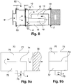
- Fig. 8 shows an arrangement of the mixing device 10 according to the invention directly after an inlet housing 60 with two possible entrances. These are, on the one hand, the axial inlet 61 and, on the other hand, the radial inlet 62.
- the mixing device 10 is adjoined by an SCR reactor.
- Fig. 9a, b show a non-inventive mixing device 70 in an angular housing 71 with only two sub-channels 72, 73 and a straight divider plate 74 in longitudinal and cross-section.
- the inlet 75 is arranged radially and is located in the vicinity of the outlet 76 from the second partial channel 73. After the inlet 75, the HWL nozzle 4 is provided.
- the exhaust gas flow is once deflected in this mixing device 70 by 180 °.
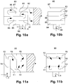
- FIG. 10a, b Another mixing device 80 with an even number of subchannels is in Fig. 10a, b shown.
- the mixing device 80 is divided into four sub-channels 84, 85, 86, 87.
- the radial inlet 88 is located in the vicinity of the outlet 89.
- the HWL nozzle 4 is located directly after the inlet 88.
- the exhaust gas flow is deflected three times by 180 °.
- dividing plates do not necessarily have to be arranged parallel to the flow direction in the SCR reactor.
- Fig. 11 a, b show a mixing device 90 in which by two straight dividers 91, 92, three sub-channels 93, 94, 95 are formed, which extend perpendicular to the flow direction in the SCR reactor. The sum of the sub-channels 93, 94, 95 gives the mixing section 96.
- the overall cross-section of the mixing device 90 is rectangular.
- Figures 12a, b show a first mixing device 100 with three concentrically arranged sub-channels 101, 102, 103. They each have a round cross-section and are with respect to their flow cross-section the same size, ie that both the cross sections of the sub-channels as well as the distances to the end faces are preferably chosen so that the flow velocity is the same everywhere.
- the sub-channels 101, 102, 103 are defined by the separating plates 104, 105.
- the exhaust gas first enters the outermost sub-channel 101.
- HWL nozzles 4a, b, c, d are provided in the front portion of the sub-channel 101 . They are evenly distributed in a cross-sectional plane.
- static mixers 106 in the rear region of the innermost subchannel 103. The gas is deflected twice in the mixing device 100, each at a stall edge by 180 °.
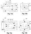
- Fig. 13a, b show a mixing device 110 with concentrically arranged sub-channels 111, 112, 113, wherein the outermost sub-channel 111 has a rectangular cross-section, while the sub-channels 112 and 113 are round in cross-section.
- the flow cross sections are selected such that the same flow velocity prevails everywhere.
- the mixing device 110 is flowed through by the exhaust gas from the outside to the inside, therefore, the reagent is also in the outermost sub-channel 111 by a plurality of HWL nozzles 4a, b, c, d added.
- static mixers 114 are present.
- the mixing device 110 flows through the exhaust gas in reverse, ie from the inside to the outside.
- the reagent is added centrally via a HWL nozzle 4 in the innermost sub-channel 113.
- a static mixer is not available.
- the mixing device 120 differs from the mixing device 110 only in the form of the cross section of the sub-channels.
- the sub-channels 121, 122, 123 are in fact all rectangular. In the Fig. 15 the mixing device is flowed through from the outside to the inside.
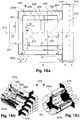
- Fig. 16a-c shows a concentrically constructed mixing device 200 in cross section ( Fig. 16a ) and in two perspective views ( Fig. 16b, c ). It is a concentric mixing system with multi-injection, which flows through from the outside to the inside.
- the mixing device 200 is flowed through by the exhaust gas from left to right.
- the exhaust gas enters the mixing device 200 through the circular feed line 201 and is directed into the outer sub-channel 202.
- the cross section of the sub-channel 202 is a circular ring.
- four injection points 203a-d are arranged symmetrically in the sub-channel 202 and take the greatest possible distance relative to each other, so they are with respect to the longitudinal axis 213 of the mixing device 200 in the mutual angle of 90 °.
- Fig. 16a two of them, 203a at the top and 203c at the bottom, the two others (203b, 203d) are in front of and behind the plane of the drawing.
- Fig. 16a two of them, 203a at the top and 203c at the bottom, the two others (203b, 203d) are in front of and behind the plane of the drawing.
- the mixture of exhaust gases and reactants flows in the middle sub-channel 205 in opposite directions to the flow direction in the outer sub-channel 202, ie from right to left.
- the middle sub-channel 205 also has an annular cross-section.
- the mixture of exhaust gas and reactant reaches the second deflection point 207, where it passes from the central sub-channel 205 in the inner sub-channel 208, thereby its flow direction around the edge of the second inner wall 209, another edge of flow, by 180 ° turned so that it flows from left to right.
- the inner sub-channel 208 corresponds to a cylinder with a circular cross-section.
- the exhaust gas reactant mixture leaves the mixing device 200, passes through the perforated plate 210 and flows through the honeycomb inlet 211 into the region of the reactor 212.
- the sub-channels 202, 205, 208 are constructed concentrically about the longitudinal axis 213.
- the best mixing levels are obtained when the mixing device 200 has an outer diameter A corresponding to the length B of the outer sub-channel 202, z. B.
- the length B of the outer sub-channel 202 defines the length of the mixing device 200.
- recesses 214, 215 in the edges of the first and second inner wall 206, 209.
- the middle sub-channel 205 At the entrance of the middle sub-channel 205 are at the edge of the first inner wall 206 four recesses 214, which are arranged symmetrically.
- the inner sub-channel 208 At the entrance of the inner sub-channel 208, it is z.
- Such a recess has z.
- the relative speed c3 0.85.
- the dimensions A-N are to be understood as ratios in parts per thousand and can be multiplied by a corresponding factor depending on the desired capacity of the mixing device. So z. B. equated with a factor of 1 in a specific embodiment 1000 per thousand with 1000 mm. It is also possible to deviate by 10% from the specified optimum measures, without losing the desired effects according to the invention.
- Fig. 17a-c shows a concentrically constructed mixing device 220 in cross section ( Fig. 17a ) and in two perspective views ( Fig. 17b, c ). It is a Concentric mixing system with single injection, which flows through from the inside to the outside.
- the mixing device 220 is flowed through by the exhaust gas from left to right.
- the exhaust gas enters the mixing device 220 through the circular feed line 221 and is mixed with the reagent in the form of droplets at the central injection point 222, which lies in an injection region 223.
- the exhaust gas reactant mixture flows through the central inner sub-channel 224, which has a circular cross-section.
- the mixture flows from left to right as far as the first deflection point 225.
- the mixture of exhaust gases and reactants passes from the inner subchannel 224 into the central subchannel 226, its flow direction being around the edge of the first inner wall 227m, which is the flow-off edge is formed, turned by 180 °.
- the mixture of exhaust gases and reactants flows in the middle sub-channel 226 in opposite directions to the flow direction in the inner sub-channel 224, ie from right to left.
- the middle sub-channel 226 has an annular cross-section.
- the exhaust gas-reactant mixture passes to the second deflection point 228, where it passes from the middle sub-channel 226 in the outer sub-channel 229, while its flow direction around the edge of the second inner wall 230, which is also designed as a stall edge, turned 180 ° so that it flows from left to right.
- the outer sub-channel 229 corresponds in cross section to a circular ring.
- the exhaust gas reactant mixture leaves the mixing device 220, passes through the perforated plate 231 and flows through the honeycomb inlet 232 into the region of the reactor 233.
- a spray funnel 234 is additionally provided in the injection area 223 at the central injection point 222. These are z. Example, to a sheet having the shape of a truncated cone, wherein the top surface facing in the direction of the incoming exhaust gas.
- the sub-channels 224, 226, 229 are constructed concentrically about the longitudinal axis 235.
- the best mixing levels are obtained when the mixing device 220 has an outer diameter A corresponding to the length B of the outer sub-channel 229, z. B.
- the length B of the outer sub-channel 229 defines the length of the mixing device 220.
- recesses 236, 237 in the edges of the first and second inner walls 227, 230.
- the middle sub-channel 226 At the entrance of the middle sub-channel 226 are located at the edge of the first inner wall 227 two recesses 236, which are arranged symmetrically.
- the outer sub-channel 229 At the entrance of the outer sub-channel 229, there are z.
- Such a recess has z.
- the dimensions AO at the mixing device 220 are to be understood as ratios and can be multiplied by a corresponding factor depending on the desired capacity of the mixing device. For a factor of 1 z. B. 1000 Per thousand are equated with 1000 mm. It is also possible to deviate by 10% from the specified optimum measures, without losing the desired effects according to the invention.
- the measured conversion in the reactor corresponded to the expected value, i. H. There were no deviations that could be attributed to insufficient mixing.
- the mixing device and the reactor were free of any deposits.
- the previously planned mixing section with a tube mixer would have a diameter of about 400mm and a length with the necessary transitions of min. Had 3 m. It would not have been possible with the available space.
- a spray funnel at a metering or injection point can also be designed as a cone, the tip of which protrudes in the direction of the incoming exhaust gas flow, and in the region of the open base surface is the Einsdüsstelle. Alternatively, it may also be a straight or cone-shaped grid or perforated plate.
- the mixing devices according to the invention enable an improved mixing of the exhaust gases with a reagent necessary for the removal of the nitrogen oxides. At the same time, these mixing devices can be made much smaller, so that their installation is possible even in systems with limited space. The already improved mixing can be further increased by additional installations.
Landscapes
- Chemical & Material Sciences (AREA)
- Engineering & Computer Science (AREA)
- Chemical Kinetics & Catalysis (AREA)
- Combustion & Propulsion (AREA)
- Environmental & Geological Engineering (AREA)
- Health & Medical Sciences (AREA)
- General Chemical & Material Sciences (AREA)
- Analytical Chemistry (AREA)
- Biomedical Technology (AREA)
- Oil, Petroleum & Natural Gas (AREA)
- Dispersion Chemistry (AREA)
- Mechanical Engineering (AREA)
- General Engineering & Computer Science (AREA)
- Toxicology (AREA)
- Exhaust Gas After Treatment (AREA)
- Exhaust Gas Treatment By Means Of Catalyst (AREA)
Claims (10)
- Dispositif de mélange pour l'utilisation lors de l'élimination catalytique des oxydes d'azote d'un flux de gaz d'échappement (7),a) dans lequel, dans le dispositif de mélange, un réactif gazeux ou liquide est réparti de façon homogène dans le flux de gaz d'échappement (7) afin que le flux de gaz d'échappement (7) puisse ensuite être amené à un réacteur (11) pour l'élimination catalytique des oxydes d'azote d'après le procédé SCR,b) dans lequel des points de déviation (8) avec respectivement un bord de séparation de l'écoulement, au niveau desquels le flux de gaz d'échappement (7) est dévié respectivement de 180° au moins deux fois, sont prévus à l'intérieur du dispositif de mélange (10),c) dans lequel le dispositif de mélange (10) est subdivisé dans sa section transversale totale en trois sous-canaux (13, 14, 15), qui sont raccordés les uns aux autres par le biais des points de déviation (8) de telle manière qu'ils forment une distance de mélange (25),caractérisé en ce que les trois sous-canaux (13, 14, 15) sont délimités par des tôles séparatrices (18, 19) disposées de manière excentrique, en ce que le dispositif de mélange (10) correspond, dans la section transversale totale, à un cercle de rayon R et en ce que les tôles séparatrices (18, 19) forment respectivement un profil d'arc pour délimiter les sous-canaux (13, 14, 15), dans lequel un rayon de courbure r du profil d'arc correspond au rayon R de la section transversale totale.
- Dispositif de mélange selon la revendication 1, caractérisé en ce que les trois sous-canaux (13, 14, 15) présentent des sections transversales de même taille et la somme des sections transversales des sous-canaux correspond à la section transversale totale du dispositif de mélange (10).
- Dispositif de mélange selon la revendication 1, caractérisé en ce que les trois sous-canaux (13, 14, 15) et les points de déviation entre les sous-canaux présentent une section transversale d'écoulement constante, qui correspond à un tiers de la section transversale totale du dispositif de mélange (10).
- Dispositif de mélange selon l'une des revendications 1 à 3, caractérisé en ce qu'au moins une station de dosage (4) pour un réactif liquide ou gazeux est disposée dans au moins un premier sous-canal (13).
- Dispositif de mélange selon l'une des revendications 1 à 4, caractérisé en ce que des éléments conducteurs (31) supplémentaires ou des mélangeurs statiques (32) sont intégrés dans les sous-canaux (13, 14, 15) du dispositif de mélange (10) ou au niveau des points de déviation.
- Dispositif de mélange selon l'une des revendications 1 à 5, caractérisé en ce que des creux (30) sont prévus au niveau des tôles séparatrices au niveau des points de déviation.
- Dispositif de mélange selon l'une des revendications 1 à 6, caractérisé en ce qu'un premier sous-canal présente une section transversale constante dans la zone entre une station de dosage et une première déviation.
- Equipement pour l'élimination catalytique des oxydes d'azote d'un flux de gaz d'échappement, dans lequel un réactif gazeux ou liquide peut être réparti de façon homogène dans le flux de gaz d'échappement (7) dans un dispositif de mélange (10) selon l'une des revendications 1 à 7 et le flux de gaz d'échappement (7) peut être amené ensuite par un réacteur (11) à l'élimination catalytique des oxydes d'azote d'après le procédé SCR.
- Equipement selon la revendication 8, caractérisé en ce que le dispositif de mélange (10) présente au niveau d'une face frontale côté sortie (23), d'où sort le flux de gaz d'échappement (7), une section transversale totale qui est aussi grande qu'une section transversale totale de la face frontale côté entrée (24) du réacteur suivant.
- Equipement selon l'une des revendications 8 ou 9, caractérisé en ce que le dispositif de mélange (10) et le réacteur (11) suivant se trouvent dans un logement commun.
Applications Claiming Priority (1)
| Application Number | Priority Date | Filing Date | Title |
|---|---|---|---|
| CH01552/11A CH705552A1 (de) | 2011-09-19 | 2011-09-19 | Mischeinrichtung. |
Publications (2)
| Publication Number | Publication Date |
|---|---|
| EP2570178A1 EP2570178A1 (fr) | 2013-03-20 |
| EP2570178B1 true EP2570178B1 (fr) | 2017-04-05 |
Family
ID=46875720
Family Applications (1)
| Application Number | Title | Priority Date | Filing Date |
|---|---|---|---|
| EP12405103.8A Active EP2570178B1 (fr) | 2011-09-19 | 2012-09-19 | Dispositif de mélange |
Country Status (2)
| Country | Link |
|---|---|
| EP (1) | EP2570178B1 (fr) |
| CH (1) | CH705552A1 (fr) |
Cited By (11)
| Publication number | Priority date | Publication date | Assignee | Title |
|---|---|---|---|---|
| US11828214B2 (en) | 2020-05-08 | 2023-11-28 | Cummins Emission Solutions Inc. | Configurable aftertreatment systems including a housing |
| US11982219B2 (en) | 2017-06-06 | 2024-05-14 | Cummins Emission Solutions Inc. | Systems and methods for mixing exhaust gases and reductant in an aftertreatment system |
| USD1042544S1 (en) | 2022-04-21 | 2024-09-17 | Cummins Emission Solutions Inc. | Aftertreatment system |
| USD1042545S1 (en) | 2022-04-21 | 2024-09-17 | Cummins Emission Solutions Inc. | Aftertreatment system |
| US12123337B2 (en) | 2021-03-18 | 2024-10-22 | Cummins Emission Solutions Inc. | Aftertreatment systems |
| US12173632B2 (en) | 2020-10-22 | 2024-12-24 | Cummins Emission Solutions Inc. | Exhaust gas aftertreatment system |
| US12188842B2 (en) | 2021-08-23 | 2025-01-07 | Cummins Emission Solutions Inc. | Outlet sampling system for aftertreatment system |
| US12264612B2 (en) | 2020-02-27 | 2025-04-01 | Cummins Emission Solutions Inc. | Mixers for use in aftertreatment systems |
| US12281605B2 (en) | 2021-07-27 | 2025-04-22 | Cummins Emision Solutions Inc. | Exhaust gas aftertreatment system |
| US12352196B2 (en) | 2021-02-02 | 2025-07-08 | Cummins Emission Solutions Inc. | Exhaust gas aftertreatment system |
| US12503969B2 (en) | 2019-12-03 | 2025-12-23 | Cummins Emission Solutions Inc. | Reductant delivery system for exhaust gas aftertreatment system |
Families Citing this family (4)
| Publication number | Priority date | Publication date | Assignee | Title |
|---|---|---|---|---|
| DE102013223313A1 (de) | 2013-11-15 | 2015-05-21 | Robert Bosch Gmbh | Abgasnachbehandlungssystem |
| DE102014206907B4 (de) * | 2014-04-10 | 2025-10-09 | Bayerische Motoren Werke Aktiengesellschaft | Abgasreinigungsanlage für Dieselmotoren |
| US10245563B2 (en) * | 2014-10-22 | 2019-04-02 | Cummins Emission Solutions, Inc. | Diesel exhaust fluid mixing body using variable cross-section switchback arrangement |
| AT518216A1 (de) * | 2016-01-21 | 2017-08-15 | Ge Jenbacher Gmbh & Co Og | Brennkraftmaschine |
Family Cites Families (7)
| Publication number | Priority date | Publication date | Assignee | Title |
|---|---|---|---|---|
| CA2088713C (fr) * | 1992-02-24 | 1999-11-16 | Hans Thomas Hug | Nettoyage des gaz d'echappement des installations de combustion |
| JP3902670B2 (ja) * | 1997-04-16 | 2007-04-11 | 株式会社荏原製作所 | 排ガス中の窒素酸化物の除去方法 |
| JP2006009608A (ja) * | 2004-06-23 | 2006-01-12 | Hino Motors Ltd | 排気浄化装置 |
| GB0606116D0 (en) * | 2006-03-28 | 2006-05-03 | Arvinmeritor A & Et Ltd | A mixing chamber for an exhaust system |
| US7856807B2 (en) * | 2008-03-17 | 2010-12-28 | Cummins Filtration Ip, Inc. | Flow reversal chambers for increased residence time |
| US20100139258A1 (en) * | 2008-12-04 | 2010-06-10 | Caterpillar Inc. | Exhaust mixer with backward flow |
| DE102009014433A1 (de) * | 2009-03-26 | 2010-09-30 | J. Eberspächer GmbH & Co. KG | Abgasbehandlungseinrichtung |
-
2011
- 2011-09-19 CH CH01552/11A patent/CH705552A1/de not_active Application Discontinuation
-
2012
- 2012-09-19 EP EP12405103.8A patent/EP2570178B1/fr active Active
Non-Patent Citations (1)
| Title |
|---|
| None * |
Cited By (12)
| Publication number | Priority date | Publication date | Assignee | Title |
|---|---|---|---|---|
| US11982219B2 (en) | 2017-06-06 | 2024-05-14 | Cummins Emission Solutions Inc. | Systems and methods for mixing exhaust gases and reductant in an aftertreatment system |
| US12503969B2 (en) | 2019-12-03 | 2025-12-23 | Cummins Emission Solutions Inc. | Reductant delivery system for exhaust gas aftertreatment system |
| US12264612B2 (en) | 2020-02-27 | 2025-04-01 | Cummins Emission Solutions Inc. | Mixers for use in aftertreatment systems |
| US11828214B2 (en) | 2020-05-08 | 2023-11-28 | Cummins Emission Solutions Inc. | Configurable aftertreatment systems including a housing |
| US12123334B2 (en) | 2020-05-08 | 2024-10-22 | Cummins Emission Solutions Inc. | Configurable aftertreatment systems including a housing |
| US12173632B2 (en) | 2020-10-22 | 2024-12-24 | Cummins Emission Solutions Inc. | Exhaust gas aftertreatment system |
| US12352196B2 (en) | 2021-02-02 | 2025-07-08 | Cummins Emission Solutions Inc. | Exhaust gas aftertreatment system |
| US12123337B2 (en) | 2021-03-18 | 2024-10-22 | Cummins Emission Solutions Inc. | Aftertreatment systems |
| US12281605B2 (en) | 2021-07-27 | 2025-04-22 | Cummins Emision Solutions Inc. | Exhaust gas aftertreatment system |
| US12188842B2 (en) | 2021-08-23 | 2025-01-07 | Cummins Emission Solutions Inc. | Outlet sampling system for aftertreatment system |
| USD1042544S1 (en) | 2022-04-21 | 2024-09-17 | Cummins Emission Solutions Inc. | Aftertreatment system |
| USD1042545S1 (en) | 2022-04-21 | 2024-09-17 | Cummins Emission Solutions Inc. | Aftertreatment system |
Also Published As
| Publication number | Publication date |
|---|---|
| EP2570178A1 (fr) | 2013-03-20 |
| CH705552A1 (de) | 2013-03-28 |
Similar Documents
| Publication | Publication Date | Title |
|---|---|---|
| EP2570178A1 (fr) | Dispositif de mélange | |
| DE19938854C5 (de) | Vorrichtung zur Verringerung des Stickoxidanteils in einem Abgas einer Verbrennungskraftmaschine | |
| EP1956206B1 (fr) | Système de nettoyage des gaz d'échappement | |
| EP2691618B1 (fr) | Unité de traitement de gaz d'échappement compacte comprenant une zone de mélange et procédé pour mélanger des gaz d'échappement | |
| EP2700442B1 (fr) | Installation de gaz d'échappement avec dispositif de mélange et/ou d'évaporation | |
| EP2687697B1 (fr) | Dispositif de mélange pour le post-traitement de gaz d'échappement | |
| EP1969213B1 (fr) | Composant destine a etre monte dans le parcours des gaz d'echappement d'un moteur a combustion interne | |
| WO2013010700A1 (fr) | Agencement permettant d'introduire un additif dans un flux de gaz | |
| DE102009053950A1 (de) | Vorrichtung zur Nachbehandlung von Abgasen von Brennkraftmaschinen | |
| EP3443209B1 (fr) | Dispositif de post-traitement des gaz d'échappement doté d'un catalyseur et d'un dispositif de mélange | |
| EP2252779A1 (fr) | Dispositif de dosage pour la reduction des substances toxiques dans les gaz d'echappement | |
| EP3797221B1 (fr) | Dispositif pour alimenter un réactif chimique dans le système d'échappement d'un moteur à combustion interne | |
| EP2820260A1 (fr) | Dispositif d'épuration d'effluents gazeux | |
| DE102008008563A1 (de) | Dosiervorrichtung zur Schadstoffverminderung in Abgasen | |
| EP3470640A2 (fr) | Module de mélange de gaz d'échappement / agent réactionnel | |
| DE112018007799T5 (de) | Zersetzungsreaktor mit körpermischung | |
| EP3704360B1 (fr) | Installation de gaz d'échappement pour le post-traitement et l'atténuation des sons de gaz d'échappement, de manière compacte et efficace | |
| DE102012014528A1 (de) | Mehrstufiger Plattenmischer | |
| DE102011120221A1 (de) | Mischer für eine Abgasanlage und Abgasanlage | |
| DE102016014966B4 (de) | Abgasnachbehandlungseinrichtung für einen Kraftwagen | |
| EP3152420B1 (fr) | Module d'injection et ligne d'échappement comprenant un module d'injection | |
| EP3068986B1 (fr) | Module d'injection et ligne de gaz d'échappement présentant un module d'injection | |
| EP4453393B1 (fr) | Mélangeur pour un système de post-traitement des gaz d'échappement d'un véhicule automobile | |
| WO2006056499A1 (fr) | Dispositif de traitement de gaz | |
| EP2823878B1 (fr) | Mélangeur à plaques à plusieurs étages |
Legal Events
| Date | Code | Title | Description |
|---|---|---|---|
| PUAI | Public reference made under article 153(3) epc to a published international application that has entered the european phase |
Free format text: ORIGINAL CODE: 0009012 |
|
| AK | Designated contracting states |
Kind code of ref document: A1 Designated state(s): AL AT BE BG CH CY CZ DE DK EE ES FI FR GB GR HR HU IE IS IT LI LT LU LV MC MK MT NL NO PL PT RO RS SE SI SK SM TR |
|
| AX | Request for extension of the european patent |
Extension state: BA ME |
|
| 17P | Request for examination filed |
Effective date: 20130918 |
|
| RBV | Designated contracting states (corrected) |
Designated state(s): AL AT BE BG CH CY CZ DE DK EE ES FI FR GB GR HR HU IE IS IT LI LT LU LV MC MK MT NL NO PL PT RO RS SE SI SK SM TR |
|
| 17Q | First examination report despatched |
Effective date: 20160222 |
|
| GRAP | Despatch of communication of intention to grant a patent |
Free format text: ORIGINAL CODE: EPIDOSNIGR1 |
|
| RIC1 | Information provided on ipc code assigned before grant |
Ipc: F01N 1/08 20060101ALI20160929BHEP Ipc: B01D 53/94 20060101ALI20160929BHEP Ipc: B01D 53/86 20060101AFI20160929BHEP Ipc: F01N 3/20 20060101ALI20160929BHEP Ipc: B01F 5/04 20060101ALI20160929BHEP Ipc: B01F 3/04 20060101ALI20160929BHEP Ipc: B01F 5/06 20060101ALI20160929BHEP |
|
| INTG | Intention to grant announced |
Effective date: 20161025 |
|
| GRAS | Grant fee paid |
Free format text: ORIGINAL CODE: EPIDOSNIGR3 |
|
| GRAA | (expected) grant |
Free format text: ORIGINAL CODE: 0009210 |
|
| AK | Designated contracting states |
Kind code of ref document: B1 Designated state(s): AL AT BE BG CH CY CZ DE DK EE ES FI FR GB GR HR HU IE IS IT LI LT LU LV MC MK MT NL NO PL PT RO RS SE SI SK SM TR |
|
| REG | Reference to a national code |
Ref country code: GB Ref legal event code: FG4D Free format text: NOT ENGLISH |
|
| REG | Reference to a national code |
Ref country code: CH Ref legal event code: EP |
|
| REG | Reference to a national code |
Ref country code: AT Ref legal event code: REF Ref document number: 881267 Country of ref document: AT Kind code of ref document: T Effective date: 20170415 |
|
| REG | Reference to a national code |
Ref country code: IE Ref legal event code: FG4D Free format text: LANGUAGE OF EP DOCUMENT: GERMAN |
|
| REG | Reference to a national code |
Ref country code: DE Ref legal event code: R096 Ref document number: 502012009967 Country of ref document: DE |
|
| REG | Reference to a national code |
Ref country code: NL Ref legal event code: MP Effective date: 20170405 |
|
| REG | Reference to a national code |
Ref country code: LT Ref legal event code: MG4D |
|
| REG | Reference to a national code |
Ref country code: FR Ref legal event code: PLFP Year of fee payment: 6 |
|
| PG25 | Lapsed in a contracting state [announced via postgrant information from national office to epo] |
Ref country code: NL Free format text: LAPSE BECAUSE OF FAILURE TO SUBMIT A TRANSLATION OF THE DESCRIPTION OR TO PAY THE FEE WITHIN THE PRESCRIBED TIME-LIMIT Effective date: 20170405 |
|
| PG25 | Lapsed in a contracting state [announced via postgrant information from national office to epo] |
Ref country code: FI Free format text: LAPSE BECAUSE OF FAILURE TO SUBMIT A TRANSLATION OF THE DESCRIPTION OR TO PAY THE FEE WITHIN THE PRESCRIBED TIME-LIMIT Effective date: 20170405 Ref country code: GR Free format text: LAPSE BECAUSE OF FAILURE TO SUBMIT A TRANSLATION OF THE DESCRIPTION OR TO PAY THE FEE WITHIN THE PRESCRIBED TIME-LIMIT Effective date: 20170706 Ref country code: ES Free format text: LAPSE BECAUSE OF FAILURE TO SUBMIT A TRANSLATION OF THE DESCRIPTION OR TO PAY THE FEE WITHIN THE PRESCRIBED TIME-LIMIT Effective date: 20170405 Ref country code: NO Free format text: LAPSE BECAUSE OF FAILURE TO SUBMIT A TRANSLATION OF THE DESCRIPTION OR TO PAY THE FEE WITHIN THE PRESCRIBED TIME-LIMIT Effective date: 20170705 Ref country code: LT Free format text: LAPSE BECAUSE OF FAILURE TO SUBMIT A TRANSLATION OF THE DESCRIPTION OR TO PAY THE FEE WITHIN THE PRESCRIBED TIME-LIMIT Effective date: 20170405 Ref country code: HR Free format text: LAPSE BECAUSE OF FAILURE TO SUBMIT A TRANSLATION OF THE DESCRIPTION OR TO PAY THE FEE WITHIN THE PRESCRIBED TIME-LIMIT Effective date: 20170405 |
|
| PG25 | Lapsed in a contracting state [announced via postgrant information from national office to epo] |
Ref country code: BG Free format text: LAPSE BECAUSE OF FAILURE TO SUBMIT A TRANSLATION OF THE DESCRIPTION OR TO PAY THE FEE WITHIN THE PRESCRIBED TIME-LIMIT Effective date: 20170705 Ref country code: RS Free format text: LAPSE BECAUSE OF FAILURE TO SUBMIT A TRANSLATION OF THE DESCRIPTION OR TO PAY THE FEE WITHIN THE PRESCRIBED TIME-LIMIT Effective date: 20170405 Ref country code: LV Free format text: LAPSE BECAUSE OF FAILURE TO SUBMIT A TRANSLATION OF THE DESCRIPTION OR TO PAY THE FEE WITHIN THE PRESCRIBED TIME-LIMIT Effective date: 20170405 Ref country code: PL Free format text: LAPSE BECAUSE OF FAILURE TO SUBMIT A TRANSLATION OF THE DESCRIPTION OR TO PAY THE FEE WITHIN THE PRESCRIBED TIME-LIMIT Effective date: 20170405 Ref country code: SE Free format text: LAPSE BECAUSE OF FAILURE TO SUBMIT A TRANSLATION OF THE DESCRIPTION OR TO PAY THE FEE WITHIN THE PRESCRIBED TIME-LIMIT Effective date: 20170405 Ref country code: IS Free format text: LAPSE BECAUSE OF FAILURE TO SUBMIT A TRANSLATION OF THE DESCRIPTION OR TO PAY THE FEE WITHIN THE PRESCRIBED TIME-LIMIT Effective date: 20170805 |
|
| REG | Reference to a national code |
Ref country code: DE Ref legal event code: R097 Ref document number: 502012009967 Country of ref document: DE |
|
| PG25 | Lapsed in a contracting state [announced via postgrant information from national office to epo] |
Ref country code: DK Free format text: LAPSE BECAUSE OF FAILURE TO SUBMIT A TRANSLATION OF THE DESCRIPTION OR TO PAY THE FEE WITHIN THE PRESCRIBED TIME-LIMIT Effective date: 20170405 Ref country code: SK Free format text: LAPSE BECAUSE OF FAILURE TO SUBMIT A TRANSLATION OF THE DESCRIPTION OR TO PAY THE FEE WITHIN THE PRESCRIBED TIME-LIMIT Effective date: 20170405 Ref country code: RO Free format text: LAPSE BECAUSE OF FAILURE TO SUBMIT A TRANSLATION OF THE DESCRIPTION OR TO PAY THE FEE WITHIN THE PRESCRIBED TIME-LIMIT Effective date: 20170405 Ref country code: CZ Free format text: LAPSE BECAUSE OF FAILURE TO SUBMIT A TRANSLATION OF THE DESCRIPTION OR TO PAY THE FEE WITHIN THE PRESCRIBED TIME-LIMIT Effective date: 20170405 Ref country code: EE Free format text: LAPSE BECAUSE OF FAILURE TO SUBMIT A TRANSLATION OF THE DESCRIPTION OR TO PAY THE FEE WITHIN THE PRESCRIBED TIME-LIMIT Effective date: 20170405 |
|
| PLBE | No opposition filed within time limit |
Free format text: ORIGINAL CODE: 0009261 |
|
| STAA | Information on the status of an ep patent application or granted ep patent |
Free format text: STATUS: NO OPPOSITION FILED WITHIN TIME LIMIT |
|
| PG25 | Lapsed in a contracting state [announced via postgrant information from national office to epo] |
Ref country code: SM Free format text: LAPSE BECAUSE OF FAILURE TO SUBMIT A TRANSLATION OF THE DESCRIPTION OR TO PAY THE FEE WITHIN THE PRESCRIBED TIME-LIMIT Effective date: 20170405 Ref country code: IT Free format text: LAPSE BECAUSE OF FAILURE TO SUBMIT A TRANSLATION OF THE DESCRIPTION OR TO PAY THE FEE WITHIN THE PRESCRIBED TIME-LIMIT Effective date: 20170405 |
|
| 26N | No opposition filed |
Effective date: 20180108 |
|
| GBPC | Gb: european patent ceased through non-payment of renewal fee |
Effective date: 20170919 |
|
| PG25 | Lapsed in a contracting state [announced via postgrant information from national office to epo] |
Ref country code: SI Free format text: LAPSE BECAUSE OF FAILURE TO SUBMIT A TRANSLATION OF THE DESCRIPTION OR TO PAY THE FEE WITHIN THE PRESCRIBED TIME-LIMIT Effective date: 20170405 Ref country code: MC Free format text: LAPSE BECAUSE OF FAILURE TO SUBMIT A TRANSLATION OF THE DESCRIPTION OR TO PAY THE FEE WITHIN THE PRESCRIBED TIME-LIMIT Effective date: 20170405 |
|
| REG | Reference to a national code |
Ref country code: IE Ref legal event code: MM4A |
|
| REG | Reference to a national code |
Ref country code: BE Ref legal event code: MM Effective date: 20170930 |
|
| PG25 | Lapsed in a contracting state [announced via postgrant information from national office to epo] |
Ref country code: LU Free format text: LAPSE BECAUSE OF NON-PAYMENT OF DUE FEES Effective date: 20170919 |
|
| PG25 | Lapsed in a contracting state [announced via postgrant information from national office to epo] |
Ref country code: IE Free format text: LAPSE BECAUSE OF NON-PAYMENT OF DUE FEES Effective date: 20170919 Ref country code: GB Free format text: LAPSE BECAUSE OF NON-PAYMENT OF DUE FEES Effective date: 20170919 |
|
| REG | Reference to a national code |
Ref country code: FR Ref legal event code: PLFP Year of fee payment: 7 |
|
| PG25 | Lapsed in a contracting state [announced via postgrant information from national office to epo] |
Ref country code: BE Free format text: LAPSE BECAUSE OF NON-PAYMENT OF DUE FEES Effective date: 20170930 |
|
| PG25 | Lapsed in a contracting state [announced via postgrant information from national office to epo] |
Ref country code: MT Free format text: LAPSE BECAUSE OF FAILURE TO SUBMIT A TRANSLATION OF THE DESCRIPTION OR TO PAY THE FEE WITHIN THE PRESCRIBED TIME-LIMIT Effective date: 20170405 |
|
| REG | Reference to a national code |
Ref country code: CH Ref legal event code: NV Representative=s name: KELLER AND PARTNER PATENTANWAELTE AG, CH |
|
| REG | Reference to a national code |
Ref country code: AT Ref legal event code: MM01 Ref document number: 881267 Country of ref document: AT Kind code of ref document: T Effective date: 20170919 |
|
| PG25 | Lapsed in a contracting state [announced via postgrant information from national office to epo] |
Ref country code: AT Free format text: LAPSE BECAUSE OF NON-PAYMENT OF DUE FEES Effective date: 20170919 |
|
| PG25 | Lapsed in a contracting state [announced via postgrant information from national office to epo] |
Ref country code: HU Free format text: LAPSE BECAUSE OF FAILURE TO SUBMIT A TRANSLATION OF THE DESCRIPTION OR TO PAY THE FEE WITHIN THE PRESCRIBED TIME-LIMIT; INVALID AB INITIO Effective date: 20120919 |
|
| PG25 | Lapsed in a contracting state [announced via postgrant information from national office to epo] |
Ref country code: CY Free format text: LAPSE BECAUSE OF NON-PAYMENT OF DUE FEES Effective date: 20170405 |
|
| PG25 | Lapsed in a contracting state [announced via postgrant information from national office to epo] |
Ref country code: MK Free format text: LAPSE BECAUSE OF FAILURE TO SUBMIT A TRANSLATION OF THE DESCRIPTION OR TO PAY THE FEE WITHIN THE PRESCRIBED TIME-LIMIT Effective date: 20170405 |
|
| PG25 | Lapsed in a contracting state [announced via postgrant information from national office to epo] |
Ref country code: TR Free format text: LAPSE BECAUSE OF FAILURE TO SUBMIT A TRANSLATION OF THE DESCRIPTION OR TO PAY THE FEE WITHIN THE PRESCRIBED TIME-LIMIT Effective date: 20170405 |
|
| PG25 | Lapsed in a contracting state [announced via postgrant information from national office to epo] |
Ref country code: PT Free format text: LAPSE BECAUSE OF FAILURE TO SUBMIT A TRANSLATION OF THE DESCRIPTION OR TO PAY THE FEE WITHIN THE PRESCRIBED TIME-LIMIT Effective date: 20170405 |
|
| PG25 | Lapsed in a contracting state [announced via postgrant information from national office to epo] |
Ref country code: AL Free format text: LAPSE BECAUSE OF FAILURE TO SUBMIT A TRANSLATION OF THE DESCRIPTION OR TO PAY THE FEE WITHIN THE PRESCRIBED TIME-LIMIT Effective date: 20170405 |
|
| REG | Reference to a national code |
Ref country code: CH Ref legal event code: PFA Owner name: HUG ENGINEERING AG, CH Free format text: FORMER OWNER: HUG ENGINEERING AG, CH |
|
| REG | Reference to a national code |
Ref country code: DE Ref legal event code: R082 Ref document number: 502012009967 Country of ref document: DE Representative=s name: PRINZ & PARTNER MBB PATENTANWAELTE RECHTSANWAE, DE |
|
| PGFP | Annual fee paid to national office [announced via postgrant information from national office to epo] |
Ref country code: DE Payment date: 20210818 Year of fee payment: 10 Ref country code: CH Payment date: 20210818 Year of fee payment: 10 |
|
| REG | Reference to a national code |
Ref country code: DE Ref legal event code: R119 Ref document number: 502012009967 Country of ref document: DE |
|
| REG | Reference to a national code |
Ref country code: CH Ref legal event code: PL |
|
| PG25 | Lapsed in a contracting state [announced via postgrant information from national office to epo] |
Ref country code: LI Free format text: LAPSE BECAUSE OF NON-PAYMENT OF DUE FEES Effective date: 20220930 Ref country code: DE Free format text: LAPSE BECAUSE OF NON-PAYMENT OF DUE FEES Effective date: 20230401 Ref country code: CH Free format text: LAPSE BECAUSE OF NON-PAYMENT OF DUE FEES Effective date: 20220930 |
|
| PGFP | Annual fee paid to national office [announced via postgrant information from national office to epo] |
Ref country code: FR Payment date: 20240925 Year of fee payment: 13 |