EP2570219A2 - Meuleuse à denture intérieure - Google Patents
Meuleuse à denture intérieure Download PDFInfo
- Publication number
- EP2570219A2 EP2570219A2 EP12006328A EP12006328A EP2570219A2 EP 2570219 A2 EP2570219 A2 EP 2570219A2 EP 12006328 A EP12006328 A EP 12006328A EP 12006328 A EP12006328 A EP 12006328A EP 2570219 A2 EP2570219 A2 EP 2570219A2
- Authority
- EP
- European Patent Office
- Prior art keywords
- coolant
- grinding
- nozzle
- internal gear
- grinding machine
- Prior art date
- Legal status (The legal status is an assumption and is not a legal conclusion. Google has not performed a legal analysis and makes no representation as to the accuracy of the status listed.)
- Withdrawn
Links
- 239000002826 coolant Substances 0.000 claims abstract description 128
- 238000007654 immersion Methods 0.000 claims description 13
- 238000007598 dipping method Methods 0.000 claims description 9
- 239000007921 spray Substances 0.000 description 5
- 239000005068 cooling lubricant Substances 0.000 description 2
- 238000009434 installation Methods 0.000 description 2
- 238000007789 sealing Methods 0.000 description 2
- 238000005299 abrasion Methods 0.000 description 1
- 230000006978 adaptation Effects 0.000 description 1
- 230000003247 decreasing effect Effects 0.000 description 1
- 238000004519 manufacturing process Methods 0.000 description 1
Images

Classifications
-
- B—PERFORMING OPERATIONS; TRANSPORTING
- B23—MACHINE TOOLS; METAL-WORKING NOT OTHERWISE PROVIDED FOR
- B23F—MAKING GEARS OR TOOTHED RACKS
- B23F23/00—Accessories or equipment combined with or arranged in, or specially designed to form part of, gear-cutting machines
- B23F23/12—Other devices, e.g. tool holders; Checking devices for controlling workpieces in machines for manufacturing gear teeth
-
- B—PERFORMING OPERATIONS; TRANSPORTING
- B23—MACHINE TOOLS; METAL-WORKING NOT OTHERWISE PROVIDED FOR
- B23Q—DETAILS, COMPONENTS, OR ACCESSORIES FOR MACHINE TOOLS, e.g. ARRANGEMENTS FOR COPYING OR CONTROLLING; MACHINE TOOLS IN GENERAL CHARACTERISED BY THE CONSTRUCTION OF PARTICULAR DETAILS OR COMPONENTS; COMBINATIONS OR ASSOCIATIONS OF METAL-WORKING MACHINES, NOT DIRECTED TO A PARTICULAR RESULT
- B23Q11/00—Accessories fitted to machine tools for keeping tools or parts of the machine in good working condition or for cooling work; Safety devices specially combined with or arranged in, or specially adapted for use in connection with, machine tools
- B23Q11/10—Arrangements for cooling or lubricating tools or work
- B23Q11/1076—Arrangements for cooling or lubricating tools or work with a cutting liquid nozzle specially adaptable to different kinds of machining operations
Definitions
- the present invention relates to an internal gear grinding machine with a grinding arm, on which a grinding spindle is arranged, and with an adjustable coolant nozzle.
- coolant nozzles are used, via which the coolant is introduced into the engagement region of the grinding wheel with the workpiece. Since the grinding wheel diameter is reduced by abrasion or by the dressing of the grinding wheel during the grinding operation, adjustable coolant nozzles are known, so that the position of the coolant nozzle can be adapted to the grinding wheel diameter.
- manually adjustable coolant nozzles are used in the prior art, which are arranged laterally adjacent to or in the radial direction extending over the grinding wheel.
- Object of the present invention is to provide an internal gear grinding machine with an adjustable coolant nozzle available, which is easier to handle and / or which better exploits the available space in the internal gear grinding machine.
- the present invention comprises in a first aspect an internal gear grinding machine with a grinding arm, on which a grinding spindle is arranged, and with an adjustable coolant nozzle.
- the coolant nozzle is adjustable via a drive.
- a drive By using a drive, the coolant nozzle no longer has to be adjusted manually, but can be adapted via the drive to the decreasing grinding wheel diameter.
- this is an electric drive, via which the adjustment of the coolant nozzle can be made.
- the internal gear grinding machine can have a control which activates the drive for adjusting the coolant nozzle and adjusts the coolant nozzle.
- the adjustment of the coolant nozzle can take place via the NC control of the grinding machine.
- the controller is designed so that the readjustment of the coolant nozzle takes place automatically, and in this case is carried out in particular automatically during the grinding operation.
- the adjustment can be carried out by the controller based on a calculated change in size of the grinding wheel.
- the adjustment can be carried out by the controller based on the stored in the machine control profile of the grinding wheel.
- the same data on the shape of the grinding wheel, which as Basis are used for the movement of the grinding head during the grinding operation, according to the invention also be used for adjustment of the coolant nozzle.
- the coolant nozzle is arranged above the grinding wheel on the grinding arm.
- the grinding spindle is arranged on a grinding arm, via which it can be moved into the workpiece in the dipping direction, in order to machine the internal toothing of the workpiece from the inside.
- the grinding arm therefore extends in the dipping direction and defines by its length the maximum possible width of the gear, which can be ground with the internal gear grinding machine.
- the arrangement according to the invention of the coolant nozzle therefore makes use of the space available on the grinding arm above the grinding spindle anyway, while consideration can be given to the space conditions otherwise limited in the area of the grinding spindle in the internal gear grinding machine.
- the installation space above the grinding wheel on the grinding arm also makes it particularly easy to use a drive for the coolant nozzle.
- the coolant nozzle of an internal gear grinding machine according to the invention can be displaceably guided via a linear guide.
- the linear guide is arranged in the grinding plane of the grinding wheel, ie the adjustment of the linear guide extends in a plane which is perpendicular to the axis of rotation of the grinding spindle, wherein the linear guide is advantageously arranged in the plane defined by the grinding wheel or grinding spindle.
- this has the advantage that the coolant can be better applied to the grinding area and only one coolant nozzle must be used.
- the linear guide of the coolant nozzle has an anti-twist device. This prevents that the orientation of the nozzle is changed unintentionally, without this would have to be clamped for this purpose as in the prior art.
- the rotation is used when the linear guide is arranged in the loop plane, since no change in the orientation of the coolant nozzle is required here due to the central arrangement of the coolant nozzle when adjusting in the longitudinal direction.
- the present invention comprises an internal gear grinding machine with a grinding arm, on which a grinding spindle is arranged, with a coolant nozzle which can be adjusted via a linear guide.
- the adjustment direction of the linear guide is inclined with respect to the immersion direction and / or with respect to a plane perpendicular to the immersion direction.
- the angle of the adjustment of the linear guide to the plane perpendicular to the immersion direction is between 5 ° and 40 °. This results in a better kinematics in the adjustment of the coolant nozzle.
- the coolant nozzle is moved not only in the dipping, but also in the direction of engagement, and will be so better adapted to the changing size of the grinding wheel position of the engagement region of the grinding slips.
- the adjustment direction of the linear guide can extend tangentially to the circumference of the grinding wheel.
- the coolant nozzle is to be adapted to a radial size change of the grinding wheel, such an arrangement still allows a sufficient adaptation to the changing grinding wheel, and requires considerably less installation space in the radial direction.
- the tangentially extending adjustment direction of the linear guide is particularly advantageous in relation to a plane perpendicular to the immersion direction.
- the coolant nozzle is further aligned transversely to the adjustment of the linear guide.
- the beam center axis of the coolant nozzle can have an angle between 45 ° and 135 °, more advantageously between 60 ° and 120 °, further between 80 ° and 100 °.
- the spray direction of the coolant nozzle is inclined to the direction of immersion of the grinding head in the workpiece, advantageously in an angular range between 5 ° and 40 °, the spray direction advantageously forward and downward to the workpiece goes.
- the first aspect of the present invention can be used independently of the second aspect of the present invention. Most preferably, however, both aspects are combined
- the coolant nozzle of the internal gear grinding machine according to the invention is arranged on a tube which is displaceably guided in a guide and at the same time serves to supply the coolant to the nozzle.
- a rack is arranged on the tube, which meshes with a pinion.
- the tube thus serves in addition to the leadership of the coolant nozzle and the supply of the coolant as a carriage of a linear drive. hereby can be achieved in the smallest space a reliable adjustment of the coolant nozzle.
- the pinion is driven by a motor of the drive of the coolant nozzle, for example via an electric motor.
- the pinion may be a normal gear or a worm gear, so that a worm drive is achieved.
- the guide of the tube has an anti-twist device.
- the guidance of the tube prevents the tube from being inadvertently twisted when adjusting the position of the coolant nozzle to accommodate the changing radius of the grinding wheel.
- the tube has an opening, via which it communicates with a space filled with coolant in order to supply the coolant nozzle with coolant, wherein the tube is displaceable relative to the space filled with coolant.
- the coolant nozzle opposite end of the tube is open and opens into the space filled with coolant.
- According to the invention can continue to be provided a seal which rests on the outer circumference of the tube and seals the filled with the coolant space.
- the linear guide of the tube is disposed within the space filled with coolant. It can also be provided that the anti-twist device for the tube is arranged within the space filled with coolant.
- the pinion of the drive is arranged in the space filled with coolant.
- the rack on the pipe in the space filled with coolant arranged.
- the motor can be outside this room and the shaft to drive the pinion through the wall of the room. All this allows a particularly simple arrangement with a minimum of sealing effort and a minimum of space.
- the last-described embodiment of the adjustable coolant nozzle can be used not only in internal gear grinding machines, but generally in gear grinding machines and in particular also in external gear grinding machines.
- the present invention therefore further comprises a gear grinding machine with a grinding spindle and with an adjustable coolant nozzle, wherein the coolant nozzle is arranged in a tube which serves to supply the coolant to the nozzle, wherein the tube has an opening through which it is filled with a coolant Room communicates to supply the coolant nozzle with coolant. Furthermore, in this case the tube is displaceable relative to the space filled with coolant, wherein a rack is arranged on the tube, which meshes with a pinion.
- the drive for adjusting the position of the coolant nozzle can be integrated in the narrowest space in the linear guide provided by the tube.
- the pinion of the drive is arranged in the space filled with coolant.
- the rack is arranged in the space filled with coolant.
- the arrangement for adjusting the coolant nozzle can be carried out as already shown above.
- an anti-rotation device can be provided for the pipe.
- the last-described gear grinding machine can also have the other features related to the coolant nozzle and their arrangement, as described above.
- the by The tube formed linear guide may be arranged in the grinding plane of the grinding machine.
- the adjustment direction of the linear guide formed by the tube can extend tangentially to the circumference of the grinding wheel. Furthermore, the coolant nozzle can be aligned transversely to the adjustment of the linear guide and thus to the longitudinal axis of the tube.
- the adjustment direction of the linear guide with respect to the immersion direction and with respect to a plane perpendicular to the immersion direction may be inclined, wherein the angle to the plane perpendicular to the immersion direction is advantageously between 5 ° and 45 °.
- the adjustment direction of the linear guide is inclined towards the nozzle upwards.
- the spray direction of the coolant nozzle is inclined to the direction of immersion of the grinding head in the workpiece, advantageously in an angular range between 5 ° and 40 °, the spray direction advantageously forward and downward to the workpiece goes.
- the tube can be arranged with the coolant nozzle above the grinding wheel on the grinding arm.
- the last-described gear grinding machine has a control which activates the drive for adjusting the coolant nozzle and adjusts the coolant nozzle.
- this control is carried out as described above according to the first aspect of the invention.
- the last-described gear grinding machine can, of course, be an internal gear grinding machine, as described in more detail above. However, it may also be an external gear grinding machine.
- the present invention further includes a coolant nozzle having a drive as described above.
- the drive comprises a pinion which meshes with a rack arranged on a pipe, wherein the coolant nozzle is arranged on the pipe and is supplied with coolant via this.
- coolant nozzle and drive are designed as already described above.
- the tube may have an opening through which it communicates with a space filled with coolant in order to supply the coolant nozzle with coolant. Furthermore, the tube can be displaced relative to the space filled with coolant.
- the present invention is particularly preferably used in internal gear grinding machines, in which the grinding spindle is arranged without the interposition of a rotation axis on the grinding arm and / or in which the grinding spindle is arranged without the interposition of a shift axis on the grinding arm and / or wherein the grinding spindle without the interposition of a Arranged in the dip direction axis on the grinding arm.
- the present invention is particularly preferably used in such internal gear grinding machines, in which the grinding spindle is rigidly arranged on the grinding arm and the movements necessary for grinding except for the rotational movement of the grinding wheel via a movement of the entire grinding arm.
- the present invention can also be used in such internal gear grinding machines, in which the grinding spindle is arranged on a movable, a grinding head forming part of the grinding arm, the is movable over one or more axes of movement relative to the rest of the grinding arm.
- the adjustabledekardüse invention is arranged on the movable part of the grinding arm and is thus moved with the grinding wheel.
- the coolant nozzle according to the invention is particularly preferably used in internal gear grinding machines, in which the grinding arm can be moved via axes which are arranged outside a radius of a workpiece to be machined. Furthermore, it can be provided that the grinding arm is rotatable about an axis of rotation and / or is movable via a first linear axis in the dipping direction and / or is movable via a shift axis in the direction of the axis of rotation of the grinding spindle and / or can be moved via a linear axis in the direction of engagement.
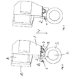
- FIG. 1 and 2 a first embodiment of an internal gear grinding machine according to the invention is shown.
- a grinding arm 1 is provided, at the lower end of a grinding spindle 2 is arranged with grinding wheel 3 clamped thereto.
- the grinding wheel 3 in the immersion direction V in the inner region of a workpiece, which with an internal toothing should be introduced.
- the workpiece would be arranged to the left of the grinding wheel below the housing section 9 of the grinding arm 1 extending outwards in the horizontal direction.
- the grinding spindle 2 is arranged rigidly on the grinding arm 1, so that all movements for grinding except for the rotational movement of the grinding wheel 3 are made by the movement of the entire grinding arm.
- the grinding arm on the connecting surface 10 with an in Fig. 3 shown machine stand 20 connected which has the necessary axes of movement.
- the axes of movement are thus outside of the workpiece 17 to be machined and could, for example, also be used for the production of external teeth with another grinding head.
- the present invention can also be applied to internal gear grinding machines with a special internal grinding head which itself has moving axes.
- the internal gear grinding machine has a coolant nozzle 4, via which the cooling lubricant can be sprayed into the processing zone.
- the position of the coolant nozzle 4 can be adjusted via a linear guide.
- the coolant nozzle 4 is arranged on a carriage, which is formed by a tube 5, which simultaneously serves the coolant supply to the nozzle 4.
- the tube 5 is linearly displaceable in a housing 6. Furthermore, a rotation for the pipe 5 is provided.
- a rack is disposed within the housing 6, which meshes with a pinion 8 shown only schematically here.
- the pinion 8 is doing driven by a likewise only schematically illustrated motor 7.
- the pinion is connected via a gearbox with the engine in connection. By turning the pinion, the slide formed by the tube 5 can be moved linearly.
- the pinion can be a normal gear or a worm gear used.
- the drive motor 7 for adjusting the position of the coolant nozzle 4 is controlled via the NC control of the grinding machine, which can make the adjustment of the coolant nozzle so automated.
- the coolant nozzle is traversable orthogonal to the grinding spindle axis.
- the linear guide formed by the housing 6 and the tube 5 is arranged above the grinding wheel, in the plane formed by the grinding wheel 3.
- the adjustment direction R of the linear guide is inclined relative to a plane perpendicular to the immersion direction V and arranged substantially tangentially to the circumference of the grinding wheel 3.
- the coolant nozzle 4 is arranged at an angle of 90 ° to the adjustment direction R of the linear guide formed by the tube 5. Furthermore, it is provided in the present invention that the spray direction of the coolant nozzle 4 is arranged inclined to the dipping direction V of the grinding head in the workpiece, and advantageously in an angular range between 5 ° and 40 °.
- a linear guide for the tube 5 is provided in the housing 21, which also has an anti-rotation. Furthermore, the tube ends 5 back in a room which is filled via a supply line with coolant. As a result, in spite of the adjustability of the tube, a simple supply of the coolant to the tube and from the tube to the coolant nozzle 4 is ensured.
- the linear guide for the tube is arranged in the region of the space filled with coolant, so that only a single seal is needed to seal the tube 5 with respect to the space filled with coolant.
- the drive unit for driving the tube is combined with the linear guide as follows:
- the rack for moving the tube is also disposed on the tube 5 in the area filled with coolant, so that there are no sealing problems by the drive.
- the pinion 8 of the drive is arranged in this space.
- a rotary feedthrough is provided for the shaft of the pinion, so that the motor 7 can be arranged outside the space filled with coolant.
- the filled with coolant space is closed to the rear by a cover 16 to the outside.
- the drive according to the invention for adjusting the coolant nozzle is arranged directly above the grinding wheel on the grinding arm of the internal grinding head.
- an adjustment unit for the coolant nozzle could also be used for external gear grinding machines, if there is also a particularly space-saving arrangement is desired.
- FIG. 3 is also the further structure of the internal gear grinding machine according to the invention to recognize.
- the extending in the dipping direction grinding arm 1 is connected via the extending in the direction of engagement housing portion 9 with a machine stand, on which movement axes are provided which perform the necessary for generating the desired grinding profile movements.
- a linear movement axis 15 is provided, through which the grinding arm can be moved in the dipping direction. Furthermore, a linear movement axis 14 is provided, through which the grinding arm can be moved orthogonal to the immersion direction. Furthermore, an axis of rotation 19 is provided to rotate the grinding arm and thus enable helical gears.
Landscapes
- Engineering & Computer Science (AREA)
- Mechanical Engineering (AREA)
- Grinding-Machine Dressing And Accessory Apparatuses (AREA)
- Gear Processing (AREA)
Applications Claiming Priority (1)
| Application Number | Priority Date | Filing Date | Title |
|---|---|---|---|
| DE102011113489A DE102011113489A1 (de) | 2011-09-15 | 2011-09-15 | Innenverzahnungsschleifmaschine |
Publications (2)
| Publication Number | Publication Date |
|---|---|
| EP2570219A2 true EP2570219A2 (fr) | 2013-03-20 |
| EP2570219A3 EP2570219A3 (fr) | 2017-01-25 |
Family
ID=46845567
Family Applications (1)
| Application Number | Title | Priority Date | Filing Date |
|---|---|---|---|
| EP12006328.4A Withdrawn EP2570219A3 (fr) | 2011-09-15 | 2012-09-07 | Meuleuse à denture intérieure |
Country Status (4)
| Country | Link |
|---|---|
| US (1) | US20130072095A1 (fr) |
| EP (1) | EP2570219A3 (fr) |
| CN (1) | CN103008794A (fr) |
| DE (1) | DE102011113489A1 (fr) |
Cited By (1)
| Publication number | Priority date | Publication date | Assignee | Title |
|---|---|---|---|---|
| CN115302337A (zh) * | 2022-10-10 | 2022-11-08 | 江苏威鹰机械有限公司 | 一种齿轮加工用打磨装置 |
Families Citing this family (6)
| Publication number | Priority date | Publication date | Assignee | Title |
|---|---|---|---|---|
| WO2015103008A1 (fr) * | 2013-12-31 | 2015-07-09 | Saint-Gobain Abrasives, Inc. | Système de distribution de liquide de refroidissement pour des applications de meulage |
| DE102016217344A1 (de) * | 2016-09-12 | 2018-03-15 | Deckel Maho Pfronten Gmbh | Kühlmittelzufuhreinrichtung und schleifwerkzeug mit einer kühlmittelzufuhreinrichtung für eine werkzeugmaschine |
| CN107695885A (zh) * | 2017-05-19 | 2018-02-16 | 佛山驰博科技有限公司 | 一种新型打磨装置 |
| CN109807404B (zh) * | 2019-02-25 | 2021-08-13 | 天津大学 | 内齿圈锥形螺旋齿砂轮磨齿方法 |
| CN114932269B (zh) * | 2022-07-19 | 2022-10-21 | 溧阳市腾新机电设备有限公司 | 一种数控内齿磨齿机 |
| CN119634845B (zh) * | 2025-02-19 | 2025-06-13 | 沈阳汉威机械制造有限公司 | 一种用于齿圈加工的刨削设备 |
Family Cites Families (19)
| Publication number | Priority date | Publication date | Assignee | Title |
|---|---|---|---|---|
| US2235582A (en) * | 1939-12-28 | 1941-03-18 | Gorton George Machine Co | Discharge nozzle holder for machine tools |
| US2515037A (en) * | 1945-11-19 | 1950-07-11 | Marquette Metal Products Co | Controllable pitch propeller |
| US3543451A (en) * | 1967-10-26 | 1970-12-01 | Day Ton Progress Corp | Accessory for machine tools |
| DD96166A1 (fr) * | 1972-06-07 | 1973-03-12 | ||
| DE2460160A1 (de) * | 1974-12-19 | 1976-06-24 | Scharmann & Co | Kuehlmittelzufuehrungseinrichtung an werkzeugmaschinen, insbesondere mit laengsverstellbarer arbeitsspindel |
| US4685250A (en) * | 1979-09-27 | 1987-08-11 | Smith Leward N | Sharpener for industrial knife blades |
| US6227775B1 (en) * | 1999-03-17 | 2001-05-08 | Arnold F. Klammer | Internal gears and splines and milling method and apparatus for manufacturing same |
| WO2001036150A1 (fr) * | 1999-11-15 | 2001-05-25 | Makino Milling Machine Co., Ltd. | Dispositif pour machine-outil et dispositif d'alimentation en liquide de travail correspondant |
| WO2002081146A1 (fr) * | 2001-04-09 | 2002-10-17 | Curtis Gary L | Procede et systeme d'administration automatique de fluide de refroidissement destines a une machine-outil |
| US6772042B1 (en) * | 2001-05-14 | 2004-08-03 | Dimensional Control, Inc. | Programmable coolant nozzle system |
| DE10322991A1 (de) * | 2003-05-21 | 2004-12-16 | Erwin Junker Maschinenfabrik Gmbh | Verfahren und Vorrichtung zum Schleifen eines Werkstücks |
| JP4192135B2 (ja) * | 2004-09-29 | 2008-12-03 | 株式会社東芝 | 加工装置及び加工方法 |
| CN2788947Y (zh) * | 2005-06-03 | 2006-06-21 | 河南科技大学 | 一种内齿轮成型磨齿机床 |
| DE102006009547A1 (de) * | 2006-02-28 | 2007-08-30 | Reishauer Ag | Verfahren zur Kontrolle der Einstellung der Kühlmitteldüse einer Schleifmaschine |
| JP5023635B2 (ja) * | 2006-09-27 | 2012-09-12 | 株式会社ジェイテクト | 研削盤のクーラント供給装置 |
| DE102008016497A1 (de) * | 2008-03-31 | 2009-10-01 | Liebherr-Verzahntechnik Gmbh | Bearbeitungskopf |
| JP5285416B2 (ja) * | 2008-12-22 | 2013-09-11 | 三菱重工業株式会社 | 内歯車研削盤及び樽形ねじ状工具のドレッシング方法 |
| DE102009043676A1 (de) * | 2009-10-01 | 2011-07-07 | KAPP GmbH, 96450 | Hartfeinbearbeitungsmaschine zum Hartfeinbearbeiten eines Werkstücks |
| DE102010026777A1 (de) * | 2010-07-09 | 2012-01-12 | Haas Schleifmaschinen Gmbh | Schleifmaschine |
-
2011
- 2011-09-15 DE DE102011113489A patent/DE102011113489A1/de not_active Withdrawn
-
2012
- 2012-09-07 EP EP12006328.4A patent/EP2570219A3/fr not_active Withdrawn
- 2012-09-12 US US13/612,536 patent/US20130072095A1/en not_active Abandoned
- 2012-09-17 CN CN2012103457560A patent/CN103008794A/zh active Pending
Non-Patent Citations (1)
| Title |
|---|
| None |
Cited By (1)
| Publication number | Priority date | Publication date | Assignee | Title |
|---|---|---|---|---|
| CN115302337A (zh) * | 2022-10-10 | 2022-11-08 | 江苏威鹰机械有限公司 | 一种齿轮加工用打磨装置 |
Also Published As
| Publication number | Publication date |
|---|---|
| EP2570219A3 (fr) | 2017-01-25 |
| CN103008794A (zh) | 2013-04-03 |
| US20130072095A1 (en) | 2013-03-21 |
| DE102011113489A1 (de) | 2013-03-21 |
Similar Documents
| Publication | Publication Date | Title |
|---|---|---|
| EP0501196B1 (fr) | Machine de taillage automatique de roues dentées pour la fabrication d'engrenages ayant des dents incurvées dans leur sens longitudinal et méthode d'opération de cette machine | |
| DE602004000917T2 (de) | Lichtbogenschweissroboter mit einer anwendbaren Struktur für die Brennerleistung | |
| DE102011113489A1 (de) | Innenverzahnungsschleifmaschine | |
| DE69917012T2 (de) | Schneckenförmige schleifscheibe und verfahren zum abrichten | |
| DE3328327C2 (de) | Vorrichtung zum spanabhebenden Bearbeiten eines Werkstücks sowie NC-gesteuerte Drehmaschine zur Druchführung eines solchen Verfahrens | |
| EP2895290B1 (fr) | Procédé pour modifier les flancs d'une dent d'une roue dentée à l'aide d'un outil | |
| EP2255910A1 (fr) | Machine à tailler les engrenages | |
| EP3455019B1 (fr) | Machine d'usinage d'engrenages comprenant un dispositif de centrage | |
| EP2178666A1 (fr) | Dispositif mécanique pour usiner des pièces en forme de barres, comprenant un dispositif d'appui de pièce | |
| DE102011103216A1 (de) | Verfahren zum Abrichten eines Werkzeugs | |
| EP3152465B1 (fr) | Dispositif d'entraînement | |
| DE4132822A1 (de) | Ferngesteuerte, frei schwenkbare spruehduese fuer eine werkzeugmaschine und dergleichen | |
| DE2615137C2 (de) | Revolverdrehmaschine | |
| DE102011015447A1 (de) | Verzahnmaschine | |
| EP2271455A1 (fr) | Tête d'usinage | |
| EP0123221A1 (fr) | Manipulateur, en particulier pour petites charges et/ou parcours à prise limité | |
| EP0721821A2 (fr) | Manipulateur pour machines-outil | |
| CH714436A2 (de) | Verfahren zur Verzahnbearbeitung eines Werkstücks mit einem Werkzeug, wobei während der Verzahnbearbeitung mittels einer Kühlmitteldüse Kühlmittel auf das Werkzeug aufgebracht wird. | |
| EP1048374B1 (fr) | Dispositif d'enroulement de ressorts, en particulier pour machines d'enroulement de ressorts | |
| DE10329724C5 (de) | Vorrichtung zum Schleifen von insbesondere Innenprofilen | |
| EP4166276A1 (fr) | Porte-buse de lubrifiant à basse température pour une machine à rectifier, machine à rectifier dotée d'un tel porte-buse de lubrifiant à basse température et procédé permettant de faire fonctionner un porte-buse de lubrifiant à basse température | |
| EP4297929A1 (fr) | Dispositif et procédé d'usinage d'une pièce à usiner, et produit programme d'ordinateur pour commander un dispositif d'usinage d'une pièce à usiner | |
| DE10245899A1 (de) | Anschlussadapter für einen Industrieroboter | |
| DE926708C (de) | Vorrichtung an Werkzeugmaschinen, die konische Fraeser oder aehnliche Werkzeuge herzustellen gestattet | |
| EP1396295A1 (fr) | Machine de cintrage avec outils de cintrage disposés aux côtés opposés d'un support porte-outils |
Legal Events
| Date | Code | Title | Description |
|---|---|---|---|
| PUAI | Public reference made under article 153(3) epc to a published international application that has entered the european phase |
Free format text: ORIGINAL CODE: 0009012 |
|
| AK | Designated contracting states |
Kind code of ref document: A2 Designated state(s): AL AT BE BG CH CY CZ DE DK EE ES FI FR GB GR HR HU IE IS IT LI LT LU LV MC MK MT NL NO PL PT RO RS SE SI SK SM TR |
|
| AX | Request for extension of the european patent |
Extension state: BA ME |
|
| PUAL | Search report despatched |
Free format text: ORIGINAL CODE: 0009013 |
|
| AK | Designated contracting states |
Kind code of ref document: A3 Designated state(s): AL AT BE BG CH CY CZ DE DK EE ES FI FR GB GR HR HU IE IS IT LI LT LU LV MC MK MT NL NO PL PT RO RS SE SI SK SM TR |
|
| AX | Request for extension of the european patent |
Extension state: BA ME |
|
| RIC1 | Information provided on ipc code assigned before grant |
Ipc: B23F 23/12 20060101AFI20161222BHEP Ipc: B23Q 11/10 20060101ALI20161222BHEP |
|
| STAA | Information on the status of an ep patent application or granted ep patent |
Free format text: STATUS: THE APPLICATION IS DEEMED TO BE WITHDRAWN |
|
| 18D | Application deemed to be withdrawn |
Effective date: 20170726 |