EP2570576A2 - Dispositif de guidage en pivotement, placé du côté de l'axe pivotant, entre un cadre solide et un battant d'une fenêtre, d'une porte ou analogue - Google Patents
Dispositif de guidage en pivotement, placé du côté de l'axe pivotant, entre un cadre solide et un battant d'une fenêtre, d'une porte ou analogue Download PDFInfo
- Publication number
- EP2570576A2 EP2570576A2 EP12183052A EP12183052A EP2570576A2 EP 2570576 A2 EP2570576 A2 EP 2570576A2 EP 12183052 A EP12183052 A EP 12183052A EP 12183052 A EP12183052 A EP 12183052A EP 2570576 A2 EP2570576 A2 EP 2570576A2
- Authority
- EP
- European Patent Office
- Prior art keywords
- wing
- clamping element
- fixed frame
- pivot
- pivoting
- Prior art date
- Legal status (The legal status is an assumption and is not a legal conclusion. Google has not performed a legal analysis and makes no representation as to the accuracy of the status listed.)
- Granted
Links
Images


Classifications
-
- E—FIXED CONSTRUCTIONS
- E05—LOCKS; KEYS; WINDOW OR DOOR FITTINGS; SAFES
- E05F—DEVICES FOR MOVING WINGS INTO OPEN OR CLOSED POSITION; CHECKS FOR WINGS; WING FITTINGS NOT OTHERWISE PROVIDED FOR, CONCERNED WITH THE FUNCTIONING OF THE WING
- E05F7/00—Accessories for wings not provided for in other groups of this subclass
- E05F7/005—Aligning devices for wings
-
- E—FIXED CONSTRUCTIONS
- E05—LOCKS; KEYS; WINDOW OR DOOR FITTINGS; SAFES
- E05D—HINGES OR SUSPENSION DEVICES FOR DOORS, WINDOWS OR WINGS
- E05D11/00—Additional features or accessories of hinges
- E05D11/0018—Anti-tamper devices
- E05D11/0027—Anti-tamper devices arranged on or near the hinge and comprising parts interlocking as the wing closes, e.g. security studs
-
- E—FIXED CONSTRUCTIONS
- E05—LOCKS; KEYS; WINDOW OR DOOR FITTINGS; SAFES
- E05F—DEVICES FOR MOVING WINGS INTO OPEN OR CLOSED POSITION; CHECKS FOR WINGS; WING FITTINGS NOT OTHERWISE PROVIDED FOR, CONCERNED WITH THE FUNCTIONING OF THE WING
- E05F7/00—Accessories for wings not provided for in other groups of this subclass
- E05F7/04—Arrangements affording protection against rattling
-
- E—FIXED CONSTRUCTIONS
- E05—LOCKS; KEYS; WINDOW OR DOOR FITTINGS; SAFES
- E05Y—INDEXING SCHEME ASSOCIATED WITH SUBCLASSES E05D AND E05F, RELATING TO CONSTRUCTION ELEMENTS, ELECTRIC CONTROL, POWER SUPPLY, POWER SIGNAL OR TRANSMISSION, USER INTERFACES, MOUNTING OR COUPLING, DETAILS, ACCESSORIES, AUXILIARY OPERATIONS NOT OTHERWISE PROVIDED FOR, APPLICATION THEREOF
- E05Y2600/00—Mounting or coupling arrangements for elements provided for in this subclass
- E05Y2600/10—Adjustable
- E05Y2600/30—Adjustment motion
- E05Y2600/31—Linear motion
- E05Y2600/314—Vertical motion
-
- E—FIXED CONSTRUCTIONS
- E05—LOCKS; KEYS; WINDOW OR DOOR FITTINGS; SAFES
- E05Y—INDEXING SCHEME ASSOCIATED WITH SUBCLASSES E05D AND E05F, RELATING TO CONSTRUCTION ELEMENTS, ELECTRIC CONTROL, POWER SUPPLY, POWER SIGNAL OR TRANSMISSION, USER INTERFACES, MOUNTING OR COUPLING, DETAILS, ACCESSORIES, AUXILIARY OPERATIONS NOT OTHERWISE PROVIDED FOR, APPLICATION THEREOF
- E05Y2600/00—Mounting or coupling arrangements for elements provided for in this subclass
- E05Y2600/10—Adjustable
- E05Y2600/30—Adjustment motion
- E05Y2600/33—Stepwise motion
-
- E—FIXED CONSTRUCTIONS
- E05—LOCKS; KEYS; WINDOW OR DOOR FITTINGS; SAFES
- E05Y—INDEXING SCHEME ASSOCIATED WITH SUBCLASSES E05D AND E05F, RELATING TO CONSTRUCTION ELEMENTS, ELECTRIC CONTROL, POWER SUPPLY, POWER SIGNAL OR TRANSMISSION, USER INTERFACES, MOUNTING OR COUPLING, DETAILS, ACCESSORIES, AUXILIARY OPERATIONS NOT OTHERWISE PROVIDED FOR, APPLICATION THEREOF
- E05Y2900/00—Application of doors, windows, wings or fittings thereof
- E05Y2900/10—Application of doors, windows, wings or fittings thereof for buildings or parts thereof
- E05Y2900/13—Type of wing
- E05Y2900/148—Windows
Definitions
- the invention further relates to a window, a door or the like having a fixed frame, with a wing which is pivotable relative to the fixed frame about a pivot axis in a closing direction from an open position to a closed position and with a pivot-axis pivoting device of the above Art.
- Such pivoting jigs are also referred to as "center closers". They serve to produce at the Schwenkachsseite pivotally mounted wings, for example on the hinge side rotatable window or door, exerted by the wing on the associated fixed frame contact pressure. Under the action of the pressure, a seal provided between the blade and the fixed frame can be compressed, thereby sealing a gap remaining between the blade and the fixed frame.
- the wing-side pivoting clamping element of the middle closer is pivoted about the fixed-frame-side pivoting clamping element by a closing movement of the wing provided therewith. With progressive closing movement of the wing, the fixed-frame-side pivoting clamping element acts on the wing on the wing-side pivoting clamping element increasingly, until finally the required contact pressure of the wing is effective.
- a middle closer presupposes a suitable mutual positioning of wing-side swing-clamping element and festritten workedem pivot-clamping element. Since at the same time the installation conditions for the pivoting clamping elements are non-uniform, it is expedient to perform the wing-side pivoting clamping element and the fixed frame-side pivoting clamping element adjustable relative to each other.
- At least one of the pivoting clamping elements is to be positioned along the wing pivot axis and then clamped in a fitting part groove of the wing or the fixed frame. Only experienced mechanics are able to estimate with sufficient certainty, over which length the relevant pivoting clamping element is to be adjusted along the wing pivot axis in order to achieve a desired change in the wing contact pressure. Inexperienced fitters are often forced to implement the respective pivoting clamping element several times along the wing pivot axis until the desired wing contact pressure is established.
- the object of the present invention is to enable a simplified compared to the prior art assembly of central closers.
- the fixed-frame-side pivot-clamping element and / or the wing-side pivot-clamping element is formed stepwise in the case of the invention.
- Support surfaces of the pivoting or clamping elements are arranged one above the other in the installation position of the pivoting clamping device along the pivot axis and offset in the transverse direction of the pivot axis against each other.
- the wing-side pivot-clamping element is supported in the caused by a closing movement of the wing clamping movement in the transverse direction of the pivot axis.
- Which of the longitudinal axis along the pivot axis supporting surfaces for supporting the wing-side pivot clamping element is used on the fixed frame side pivot clamping element depends on the position which occupies the wing-side pivot clamping element and / or the fixed frame side pivot clamping element along the pivot axis.
- the support surface used to support the wing-side pivot clamping element in turn determined due to its position in the transverse direction of the pivot axis, the amount of loading of the wing-side pivot clamping element by the fixed frame side pivot clamping element and thus the size of the pressure exerted by the wing on the fixed frame contact pressure.
- the adjustment of the contact pressure is due to the step-like design of the pivoting or clamping elements in combination with their inventive feasibility along the pivot axis extremely simple.
- the fixed-frame-side pivoting clamping element are mounted on the fixed frame and the wing-side pivoting clamping element on the wing initially with a basic setting along the pivot axis. If it is found in the course of the wing assembly or on the already mounted wing that the contact pressure of the wing in the default setting of the wing-side pivoting clamping element and the fixed frame side pivoting clamping element does not correspond to the desired contact pressure, so at least one of the pivoting clamping elements along the pivot axis implemented become.
- a conversion of the pivoting or the clamping elements along the pivot axis may be required in particular if tolerances occur on the wing and / or on the fixed frame or if the fixed frame or the wing due to temperature, such as under sunlight, changed its shape, that at the given setting of the swing clamping elements a sufficient contact pressure of the wing is not guaranteed.
- the support of the wing-side pivoting clamping element is carried on the fixed frame side pivoting clamping element on a different support surface than before. This is accompanied by a change in the pressure exerted by the wing on the fixed frame contact pressure.
- the line of action of the force exerted by the fixed-frame-side pivoting clamping element with the wing closed on the wing-side pivoting clamping element advantageously extends in the direction of the wing contact pressure, namely perpendicular to the main plane of the fixed frame.
- the pivoting jig can remove forces in the fixed frame exerted on the outside of the wing perpendicular to the main plane of the fixed frame. This enables the swing jig to make a contribution to securing the relevant window, door or the like against unauthorized opening.
- a ramp ensures a shock-free and thus low-wear clamping movement of the wing-side pivot clamping element to the fixed frame-side pivoting clamping element.
- mounting holes are in the case of a further embodiment of the invention the pivoting clamping device according to the invention as connecting means on the fixed frame side and / or on the wing-side pivoting clamping element on the one hand and on the fixed frame and / or the wing on the other hand mounting openings provided with alternating mutual assignment with each other Cover can be brought.
- At least one fastening screw which passes through two mutually associated fastening openings, serves to fix the pivoting or clamping elements in question on the fixed frame or on the wing.
- Such screw connections allow a handling-friendly production and a handling-friendly release of the connection between the one or more pivoting clamping elements on the one hand and the fixed frame or the wing on the other.
- the pivoting clamping device is provided according to claim 7.
- an adjusting projection provided on the fixed-frame-side pivoting clamping element and / or on the blade-side pivoting clamping element is used only for the basic setting of the relevant pivoting clamping elements. Is exceptionally make an adjustment of the wing contact pressure by reacting the or the pivoting clamping elements along the pivot axis, the adjusting projection is removed prior to assembly of the pivoting or clamping elements in the changed position. Depending on the material of the pivoting or clamping elements of the Justiervorsprung example, be cut or abraded.
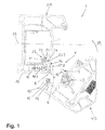
- a window 1 is in the FIGS. 1 and 2 in the scope of a belt-side vertical beam 2 of a fixed frame 3 and a belt-side vertical spar 4 of a wing 5 shown. It is in the window 1 to a plastic window, the wing 5 is pivotally mounted about a geometric pivot axis 6 of conventional design about a geometric pivot axis 6 on the fixed frame 3. As a hinged fitting a concealed fitting is provided. Accordingly, when closing, the wing 5 performs not only a rotational movement about the pivot axis 6 but also a translational movement toward the fixed frame 3. The pivot axis 6 therefore changes its position during the closing movement of the wing 5.
- a pivot-axis pivoting jig 7 is provided between the fixed frame 3 and the wing 5. This comprises a schwenkachs wh connected to the fixed frame 3 fixed frame side pivot clamping element 8 and a schwenkachs wh connected to the wing 5 wing-side pivoting clamping element. 9
- the wing-side pivot-clamping element 9 is partly used in a fitting part 10, which extends on the folded side of the vertical spar 4 in the circumferential direction of the wing 5.
- the fitting part 10 is the wing-side pivot-clamping element 9 with the wing 5 relative to this immovably screwed.
- a nose-like projection 11 of the wing-side pivot clamping element 9 is opposite to the rebate surface on the vertical spar 4 of the wing 5 to the fixed frame side pivoting clamping element 8 ago and has a contact surface 12.
- the contact surface 12 of the wing-side pivot clamping element 9 extends in the FIGS. 1 and 2 perpendicular to the plane of the drawing and extends as a flat surface parallel to the pivot axis 6.
- wing flap 13 Near the fitting part 10 of the vertical spar 4 of the wing 5 forms a wing flap 13 from.
- a sealing groove 14 on the wing flap 13 is fixed as a roll-over seal 15 extending in the circumferential direction of the blade 5 elastically compressible rubber seal conventional design.
- the fixed-frame-side pivot-clamping element 8 is placed on a folding surface on the vertical spar 2 of the fixed frame 3.
- FIG. 4 is the location of the cutting plane of FIG. 1 on the fixed frame side pivoting clamping element 8 illustrated by the line II.
- the mounting holes 17.1, 17.2, 17.3, 17.4 on the fixed frame-side pivot clamping element 8 are spaced from each other with a uniform distance 19. A mutual distance of the same size, the attachment opening 18.1 and the adjacent attachment opening on the fixed frame 3.
- the attachment openings 17.1, 17.2, 17.3, 17.4 on the fixed frame side pivot clamping element 8 on the one hand and the mounting opening 18 and the adjacent mounting opening on the fixed frame 3 on the other hand represent connecting means by which the fixed frame side swing clamping element 8 in the below still in Individual manner described in different positions along the pivot axis 6 can be connected to the fixed frame 3.
- the fixed-frame-side pivoting clamping element 8 engages with a pin-shaped adjusting projection 21 with an exact fit in an adjusting opening 22 on the fixed frame 3 ( FIG. 1 ).
- the peg-shaped Justiervorsprung 21 adjacent the fixed-frame-side pivot clamping element 8 is provided with a strip-shaped Justiervorsprung 31 which extends along the pivot axis 6 and which is arranged in the interior of a frame extending to the fixed frame 3 in Falz prevalentscardi compassion strengtheningprofilnut 32 ( FIG. 2 ).
- the pin-shaped adjusting projection 21 and the adjusting opening 22 and the strip-shaped adjusting projection 31 and the compassionprofilnut 32 form adjusting elements of an adjusting device 23, which aligns the fixed frame-side pivot clamping element 8 with a desired position on the fixed frame 3.
- the pin-shaped adjusting projection 21 defines together with the adjusting opening 22 that position along the pivot axis 6, which the fixed-frame-side pivot-clamping element 8 in the basic setting according to the FIGS. 1 and 2 occupies.
- the strip-shaped projection 31 and the compassionprofilnut 32 ensure that the fixed-frame-side pivot-clamping element 8 is always aligned with its longitudinal axis parallel to the pivot axis 6 and the vertical spar 2 of the fixed frame 3.
- FIG. 6 shows the fixed-frame-side pivot-clamping element 8 in the view in the direction of arrow VI in FIG. 3 ,
- the support leg 20 is adjoined by a support leg 24, which is angled relative to this, of the fixed-frame-side pivoting clamping element 8.
- a support leg 24 planar support surfaces 25.1, 25.2, 25.3 are formed, which follow one another in the installation position of the fixed frame side pivot clamping element 8 along the pivot axis 6 and thereby extend parallel to the pivot axis 6 and are offset in the transverse direction of the pivot axis 6 against each other.
- the fixed-frame-side pivoting clamping element 8 give the support surfaces 25.1, 25.2, 25.3 a step-like shape. This is especially in FIG. 4 to recognize.
- FIG. 5 shows the support surfaces 25.1, 25.2, 25.3 in the view in the direction of arrow V in FIG. 3 ,
- the extent of the nose-like projection 11 and provided on this contact surface 12 of the wing-side pivot clamping element 9 in the direction of the pivot axis 6 is smaller than the corresponding Extension of each of the ramps 27.1, 27.2, 27.3 and also smaller than the corresponding extent of each of the support surfaces 25.1, 25.2, 25.3.
- the nose-like projection 11 of the wing-side pivot clamping element 9 slides with continued closing movement of the wing 5 on the ramp 27.2 of the fixed frame side pivot clamping element 8 in the closing direction 28.
- the course of the ramp 27. 27 is such chosen that the nose-like projection 11 is increasingly acted upon in its movement on the ramp 26.2 and thus also the wing-side pivot clamping element 9 rigidly connected wings 5 with a force component perpendicular to a in the FIGS. 1 and 2 dash-dotted lines indicated main plane 29 of the fixed frame 3 in the direction of the fixed frame 3 extends.
- the fastening openings 17.1, 17.2 on the fixed-frame-side pivoting clamping element 8 with the fastening opening 18.1 and the adjoining fastening opening on the fixed frame 3 are to overlap.
- the mounting screws 16 are screwed through the mounting holes 17.1, 17.2 on the fixed frame side pivot clamping element 8 in the underlying mounting hole 18.1 and the adjacent mounting hole on the fixed frame 3 and thereby the fixed frame side swing clamping element 8 with respect to the FIGS. 1 and 2 fixed along the pivot axis 6 to the viewer displaced position on the fixed frame 3.
- the pin-shaped adjusting projection 21 is to be removed before moving the fixed-frame-side pivoting clamping element 8.
- the pin-like adjusting projection 21 can be cut off or abraded.
- the peg-like Justiervorsprung 21 of the strip-shaped Justiervorsprung 31 remains in any case on the longitudinal axis of the swivel axis 6 to be converted fixed frame side pivot clamping element 8.
- the strip-shaped Justiervorsprung 31 slides along the termeprafilnut 32 and thereby performs the fixed frame-side swing clamping element 8 in the Direction of the transfer movement.
- the fixed-frame-side pivot-clamping element 8 is positioned by the strip-shaped Justiervorsprung 31 with its desired position parallel to the vertical spar 2 on the fixed frame 3.
- the nose-like projection 11 of the wing-side pivot clamping element 9 acts together with the ramp 11 in the movement of the wing 5 in the closing direction 28 and finally reaches the support surface 25.1 of the fixed frame side pivot clamping element 8 with this in the back grip.
- the support surface 25.1 is offset from the previously effective support surface 25.2 of the fixed frame side pivot clamping element 8 perpendicular to the main plane 29 of the fixed frame 3 to the visible surface 30 of the fixed frame 3, the contact pressure, which the wing 5 perpendicular to the main plane 29th the fixed frame 3 exerts on this, as a result of the described implementation of the fixed frame side pivot clamping element 8 from.
- the contact pressure exerted by the wing 5 on the fixed frame 3 can be increased.
- the fixed-frame side Swivel clamping element 8 starting from the ratios in accordance with Figures 1 and 2 along the pivot axis 6 in a position to implement, in which the mounting holes 17.3, 17.4 are assigned to the fixed frame side pivot clamping element 8 of the mounting hole 18.1 and the adjacent mounting opening on the fixed frame 3.
- the nose-like projection 11 of the wing-side pivoting clamping element 9 cooperates with the ramping ramp 27.3 and with the support surface 25.3 on the fixed frame-side pivoting clamping element 8.
- the support surface 25.3 is opposite to that according to the FIGS.
- the amount of Umsetziolo is always the same and by the distance dimension 19 of the mounting holes 17.1, 17.2, 17.3, 17.4 on the fixed frame side pivot clamping element 8 and the matching distance of the Mounting opening 18. 1 and the adjacent attachment opening predetermined on the fixed frame 3.
Landscapes
- Engineering & Computer Science (AREA)
- Mechanical Engineering (AREA)
- Securing Of Glass Panes Or The Like (AREA)
- Door And Window Frames Mounted To Openings (AREA)
- Automatic Assembly (AREA)
- Hinges (AREA)
- Mutual Connection Of Rods And Tubes (AREA)
Applications Claiming Priority (1)
| Application Number | Priority Date | Filing Date | Title |
|---|---|---|---|
| DE201110082807 DE102011082807B3 (de) | 2011-09-16 | 2011-09-16 | Schwenkachsseitige Schwenk-Spannvorrichtung zwischen einem festen Rahmen und einem Flügel eines Fensters, einer Tür oder dergleichen |
Publications (3)
| Publication Number | Publication Date |
|---|---|
| EP2570576A2 true EP2570576A2 (fr) | 2013-03-20 |
| EP2570576A3 EP2570576A3 (fr) | 2013-09-11 |
| EP2570576B1 EP2570576B1 (fr) | 2014-11-05 |
Family
ID=46796448
Family Applications (1)
| Application Number | Title | Priority Date | Filing Date |
|---|---|---|---|
| EP20120183052 Active EP2570576B1 (fr) | 2011-09-16 | 2012-09-05 | Dispositif de guidage en pivotement, placé du côté de l'axe pivotant, entre un cadre solide et un battant d'une fenêtre, d'une porte ou analogue |
Country Status (2)
| Country | Link |
|---|---|
| EP (1) | EP2570576B1 (fr) |
| DE (1) | DE102011082807B3 (fr) |
Cited By (1)
| Publication number | Priority date | Publication date | Assignee | Title |
|---|---|---|---|---|
| EP4696857A1 (fr) * | 2024-08-12 | 2026-02-18 | profine GmbH | Clip d'ecartement pour portes et fenetres pivotantes |
Families Citing this family (1)
| Publication number | Priority date | Publication date | Assignee | Title |
|---|---|---|---|---|
| GB2638376A (en) * | 2023-11-10 | 2025-08-27 | G T Window Products Ltd | Anti-tamper device |
Citations (1)
| Publication number | Priority date | Publication date | Assignee | Title |
|---|---|---|---|---|
| EP1411201A2 (fr) | 2002-10-15 | 2004-04-21 | Roto Frank Ag | Ferrure |
-
2011
- 2011-09-16 DE DE201110082807 patent/DE102011082807B3/de not_active Expired - Fee Related
-
2012
- 2012-09-05 EP EP20120183052 patent/EP2570576B1/fr active Active
Patent Citations (1)
| Publication number | Priority date | Publication date | Assignee | Title |
|---|---|---|---|---|
| EP1411201A2 (fr) | 2002-10-15 | 2004-04-21 | Roto Frank Ag | Ferrure |
Cited By (1)
| Publication number | Priority date | Publication date | Assignee | Title |
|---|---|---|---|---|
| EP4696857A1 (fr) * | 2024-08-12 | 2026-02-18 | profine GmbH | Clip d'ecartement pour portes et fenetres pivotantes |
Also Published As
| Publication number | Publication date |
|---|---|
| EP2570576B1 (fr) | 2014-11-05 |
| DE102011082807B3 (de) | 2012-10-18 |
| EP2570576A3 (fr) | 2013-09-11 |
Similar Documents
| Publication | Publication Date | Title |
|---|---|---|
| DE102011007004B4 (de) | Rollobaueinheit für ein Kraftfahrzeug | |
| EP1080290A1 (fr) | Dispositif tampon | |
| EP2525032A2 (fr) | Penture | |
| EP2130997B1 (fr) | Porte avec charnière | |
| EP3808926B1 (fr) | Dispositif de fixation pivotante d'un vantail de porte sur un dormant | |
| EP2927409B1 (fr) | Joint pour une porte coulissante | |
| EP2708692B1 (fr) | Ferrure destinée à être agencée de façon cachée dans la feuillure entre un battant et un cadre de fenêtre, de porte ou analogue | |
| EP2754813B1 (fr) | Charnière, notamment pour portes et fenêtres en plastique | |
| EP2570576B1 (fr) | Dispositif de guidage en pivotement, placé du côté de l'axe pivotant, entre un cadre solide et un battant d'une fenêtre, d'une porte ou analogue | |
| EP1893834B1 (fr) | Dispositif d'ouverture de porte electrique pour portes en verre | |
| EP3494272B1 (fr) | Fenêtre, porte ou similaire comprenant un compas entre un cadre fixe et un battant | |
| EP3118404B1 (fr) | Charniere, notamment pour portes en matiere synthetique et fenetre en matiere synthetique | |
| EP2169167B1 (fr) | Dispositif de réglage de la distance entre deux chariots se déplaçant sur un rail commun et procédé | |
| DE102007043757B3 (de) | Verstellbares Flügelbandteil eines Gelenkbandes | |
| DE10058483B4 (de) | Selbst sperrende Verriegelungseinrichtung für Flügel mit Überschlag | |
| EP1862623B1 (fr) | Sécurité anti-basculement | |
| WO2010043660A1 (fr) | Paumelle pour portes ou fenêtres | |
| DE202013100103U1 (de) | Kippbeschlag für einen Fenster- oder Türflügel | |
| DE4313134C1 (de) | Amboß-Gehrungsschere zum Schneiden von Dichtungsprofilen | |
| DE102006007672A1 (de) | Dichtungsanordnung eines Fensters, einer Tür oder dgl. | |
| EP1635022B1 (fr) | Charnière avec une penture en forme de peigne | |
| DE102007031497A1 (de) | Verbesserte, aufrollbare Markise | |
| DE102007025857A1 (de) | Gelenkband für Türen oder Fenster | |
| DE102022118175B3 (de) | Fassadentür | |
| EP3707335A1 (fr) | Chambranle métallique |
Legal Events
| Date | Code | Title | Description |
|---|---|---|---|
| PUAI | Public reference made under article 153(3) epc to a published international application that has entered the european phase |
Free format text: ORIGINAL CODE: 0009012 |
|
| AK | Designated contracting states |
Kind code of ref document: A2 Designated state(s): AL AT BE BG CH CY CZ DE DK EE ES FI FR GB GR HR HU IE IS IT LI LT LU LV MC MK MT NL NO PL PT RO RS SE SI SK SM TR |
|
| AX | Request for extension of the european patent |
Extension state: BA ME |
|
| PUAL | Search report despatched |
Free format text: ORIGINAL CODE: 0009013 |
|
| AK | Designated contracting states |
Kind code of ref document: A3 Designated state(s): AL AT BE BG CH CY CZ DE DK EE ES FI FR GB GR HR HU IE IS IT LI LT LU LV MC MK MT NL NO PL PT RO RS SE SI SK SM TR |
|
| AX | Request for extension of the european patent |
Extension state: BA ME |
|
| RIC1 | Information provided on ipc code assigned before grant |
Ipc: E05F 7/00 20060101ALI20130807BHEP Ipc: E05D 11/00 20060101AFI20130807BHEP |
|
| 17P | Request for examination filed |
Effective date: 20130914 |
|
| RBV | Designated contracting states (corrected) |
Designated state(s): AL AT BE BG CH CY CZ DE DK EE ES FI FR GB GR HR HU IE IS IT LI LT LU LV MC MK MT NL NO PL PT RO RS SE SI SK SM TR |
|
| GRAP | Despatch of communication of intention to grant a patent |
Free format text: ORIGINAL CODE: EPIDOSNIGR1 |
|
| INTG | Intention to grant announced |
Effective date: 20140508 |
|
| GRAS | Grant fee paid |
Free format text: ORIGINAL CODE: EPIDOSNIGR3 |
|
| GRAA | (expected) grant |
Free format text: ORIGINAL CODE: 0009210 |
|
| AK | Designated contracting states |
Kind code of ref document: B1 Designated state(s): AL AT BE BG CH CY CZ DE DK EE ES FI FR GB GR HR HU IE IS IT LI LT LU LV MC MK MT NL NO PL PT RO RS SE SI SK SM TR |
|
| REG | Reference to a national code |
Ref country code: GB Ref legal event code: FG4D Free format text: NOT ENGLISH |
|
| REG | Reference to a national code |
Ref country code: CH Ref legal event code: EP |
|
| REG | Reference to a national code |
Ref country code: AT Ref legal event code: REF Ref document number: 694764 Country of ref document: AT Kind code of ref document: T Effective date: 20141115 |
|
| REG | Reference to a national code |
Ref country code: IE Ref legal event code: FG4D Free format text: LANGUAGE OF EP DOCUMENT: GERMAN |
|
| REG | Reference to a national code |
Ref country code: DE Ref legal event code: R096 Ref document number: 502012001529 Country of ref document: DE Effective date: 20141218 |
|
| REG | Reference to a national code |
Ref country code: NL Ref legal event code: VDEP Effective date: 20141105 |
|
| REG | Reference to a national code |
Ref country code: LT Ref legal event code: MG4D |
|
| PG25 | Lapsed in a contracting state [announced via postgrant information from national office to epo] |
Ref country code: ES Free format text: LAPSE BECAUSE OF FAILURE TO SUBMIT A TRANSLATION OF THE DESCRIPTION OR TO PAY THE FEE WITHIN THE PRESCRIBED TIME-LIMIT Effective date: 20141105 Ref country code: NO Free format text: LAPSE BECAUSE OF FAILURE TO SUBMIT A TRANSLATION OF THE DESCRIPTION OR TO PAY THE FEE WITHIN THE PRESCRIBED TIME-LIMIT Effective date: 20150205 Ref country code: PT Free format text: LAPSE BECAUSE OF FAILURE TO SUBMIT A TRANSLATION OF THE DESCRIPTION OR TO PAY THE FEE WITHIN THE PRESCRIBED TIME-LIMIT Effective date: 20150305 Ref country code: IS Free format text: LAPSE BECAUSE OF FAILURE TO SUBMIT A TRANSLATION OF THE DESCRIPTION OR TO PAY THE FEE WITHIN THE PRESCRIBED TIME-LIMIT Effective date: 20150305 Ref country code: LT Free format text: LAPSE BECAUSE OF FAILURE TO SUBMIT A TRANSLATION OF THE DESCRIPTION OR TO PAY THE FEE WITHIN THE PRESCRIBED TIME-LIMIT Effective date: 20141105 Ref country code: FI Free format text: LAPSE BECAUSE OF FAILURE TO SUBMIT A TRANSLATION OF THE DESCRIPTION OR TO PAY THE FEE WITHIN THE PRESCRIBED TIME-LIMIT Effective date: 20141105 Ref country code: NL Free format text: LAPSE BECAUSE OF FAILURE TO SUBMIT A TRANSLATION OF THE DESCRIPTION OR TO PAY THE FEE WITHIN THE PRESCRIBED TIME-LIMIT Effective date: 20141105 |
|
| PG25 | Lapsed in a contracting state [announced via postgrant information from national office to epo] |
Ref country code: RS Free format text: LAPSE BECAUSE OF FAILURE TO SUBMIT A TRANSLATION OF THE DESCRIPTION OR TO PAY THE FEE WITHIN THE PRESCRIBED TIME-LIMIT Effective date: 20141105 Ref country code: HR Free format text: LAPSE BECAUSE OF FAILURE TO SUBMIT A TRANSLATION OF THE DESCRIPTION OR TO PAY THE FEE WITHIN THE PRESCRIBED TIME-LIMIT Effective date: 20141105 Ref country code: PL Free format text: LAPSE BECAUSE OF FAILURE TO SUBMIT A TRANSLATION OF THE DESCRIPTION OR TO PAY THE FEE WITHIN THE PRESCRIBED TIME-LIMIT Effective date: 20141105 Ref country code: GR Free format text: LAPSE BECAUSE OF FAILURE TO SUBMIT A TRANSLATION OF THE DESCRIPTION OR TO PAY THE FEE WITHIN THE PRESCRIBED TIME-LIMIT Effective date: 20150206 Ref country code: LV Free format text: LAPSE BECAUSE OF FAILURE TO SUBMIT A TRANSLATION OF THE DESCRIPTION OR TO PAY THE FEE WITHIN THE PRESCRIBED TIME-LIMIT Effective date: 20141105 Ref country code: CY Free format text: LAPSE BECAUSE OF FAILURE TO SUBMIT A TRANSLATION OF THE DESCRIPTION OR TO PAY THE FEE WITHIN THE PRESCRIBED TIME-LIMIT Effective date: 20141105 Ref country code: SE Free format text: LAPSE BECAUSE OF FAILURE TO SUBMIT A TRANSLATION OF THE DESCRIPTION OR TO PAY THE FEE WITHIN THE PRESCRIBED TIME-LIMIT Effective date: 20141105 |
|
| PG25 | Lapsed in a contracting state [announced via postgrant information from national office to epo] |
Ref country code: DK Free format text: LAPSE BECAUSE OF FAILURE TO SUBMIT A TRANSLATION OF THE DESCRIPTION OR TO PAY THE FEE WITHIN THE PRESCRIBED TIME-LIMIT Effective date: 20141105 Ref country code: CZ Free format text: LAPSE BECAUSE OF FAILURE TO SUBMIT A TRANSLATION OF THE DESCRIPTION OR TO PAY THE FEE WITHIN THE PRESCRIBED TIME-LIMIT Effective date: 20141105 Ref country code: EE Free format text: LAPSE BECAUSE OF FAILURE TO SUBMIT A TRANSLATION OF THE DESCRIPTION OR TO PAY THE FEE WITHIN THE PRESCRIBED TIME-LIMIT Effective date: 20141105 Ref country code: SK Free format text: LAPSE BECAUSE OF FAILURE TO SUBMIT A TRANSLATION OF THE DESCRIPTION OR TO PAY THE FEE WITHIN THE PRESCRIBED TIME-LIMIT Effective date: 20141105 |
|
| REG | Reference to a national code |
Ref country code: DE Ref legal event code: R097 Ref document number: 502012001529 Country of ref document: DE |
|
| PLBE | No opposition filed within time limit |
Free format text: ORIGINAL CODE: 0009261 |
|
| STAA | Information on the status of an ep patent application or granted ep patent |
Free format text: STATUS: NO OPPOSITION FILED WITHIN TIME LIMIT |
|
| 26N | No opposition filed |
Effective date: 20150806 |
|
| PG25 | Lapsed in a contracting state [announced via postgrant information from national office to epo] |
Ref country code: IT Free format text: LAPSE BECAUSE OF FAILURE TO SUBMIT A TRANSLATION OF THE DESCRIPTION OR TO PAY THE FEE WITHIN THE PRESCRIBED TIME-LIMIT Effective date: 20141105 |
|
| PG25 | Lapsed in a contracting state [announced via postgrant information from national office to epo] |
Ref country code: SI Free format text: LAPSE BECAUSE OF FAILURE TO SUBMIT A TRANSLATION OF THE DESCRIPTION OR TO PAY THE FEE WITHIN THE PRESCRIBED TIME-LIMIT Effective date: 20141105 |
|
| PG25 | Lapsed in a contracting state [announced via postgrant information from national office to epo] |
Ref country code: LU Free format text: LAPSE BECAUSE OF FAILURE TO SUBMIT A TRANSLATION OF THE DESCRIPTION OR TO PAY THE FEE WITHIN THE PRESCRIBED TIME-LIMIT Effective date: 20150905 Ref country code: MC Free format text: LAPSE BECAUSE OF FAILURE TO SUBMIT A TRANSLATION OF THE DESCRIPTION OR TO PAY THE FEE WITHIN THE PRESCRIBED TIME-LIMIT Effective date: 20141105 |
|
| PG25 | Lapsed in a contracting state [announced via postgrant information from national office to epo] |
Ref country code: RO Free format text: LAPSE BECAUSE OF FAILURE TO SUBMIT A TRANSLATION OF THE DESCRIPTION OR TO PAY THE FEE WITHIN THE PRESCRIBED TIME-LIMIT Effective date: 20141105 |
|
| REG | Reference to a national code |
Ref country code: IE Ref legal event code: MM4A |
|
| REG | Reference to a national code |
Ref country code: FR Ref legal event code: ST Effective date: 20160531 |
|
| PG25 | Lapsed in a contracting state [announced via postgrant information from national office to epo] |
Ref country code: IE Free format text: LAPSE BECAUSE OF NON-PAYMENT OF DUE FEES Effective date: 20150905 |
|
| PG25 | Lapsed in a contracting state [announced via postgrant information from national office to epo] |
Ref country code: FR Free format text: LAPSE BECAUSE OF NON-PAYMENT OF DUE FEES Effective date: 20150930 |
|
| PG25 | Lapsed in a contracting state [announced via postgrant information from national office to epo] |
Ref country code: MT Free format text: LAPSE BECAUSE OF FAILURE TO SUBMIT A TRANSLATION OF THE DESCRIPTION OR TO PAY THE FEE WITHIN THE PRESCRIBED TIME-LIMIT Effective date: 20141105 |
|
| GBPC | Gb: european patent ceased through non-payment of renewal fee |
Effective date: 20160905 |
|
| PG25 | Lapsed in a contracting state [announced via postgrant information from national office to epo] |
Ref country code: SM Free format text: LAPSE BECAUSE OF FAILURE TO SUBMIT A TRANSLATION OF THE DESCRIPTION OR TO PAY THE FEE WITHIN THE PRESCRIBED TIME-LIMIT Effective date: 20141105 Ref country code: BG Free format text: LAPSE BECAUSE OF FAILURE TO SUBMIT A TRANSLATION OF THE DESCRIPTION OR TO PAY THE FEE WITHIN THE PRESCRIBED TIME-LIMIT Effective date: 20141105 Ref country code: HU Free format text: LAPSE BECAUSE OF FAILURE TO SUBMIT A TRANSLATION OF THE DESCRIPTION OR TO PAY THE FEE WITHIN THE PRESCRIBED TIME-LIMIT; INVALID AB INITIO Effective date: 20120905 |
|
| PG25 | Lapsed in a contracting state [announced via postgrant information from national office to epo] |
Ref country code: GB Free format text: LAPSE BECAUSE OF NON-PAYMENT OF DUE FEES Effective date: 20160905 Ref country code: BE Free format text: LAPSE BECAUSE OF NON-PAYMENT OF DUE FEES Effective date: 20150930 |
|
| PGFP | Annual fee paid to national office [announced via postgrant information from national office to epo] |
Ref country code: CH Payment date: 20170925 Year of fee payment: 6 |
|
| PG25 | Lapsed in a contracting state [announced via postgrant information from national office to epo] |
Ref country code: MK Free format text: LAPSE BECAUSE OF FAILURE TO SUBMIT A TRANSLATION OF THE DESCRIPTION OR TO PAY THE FEE WITHIN THE PRESCRIBED TIME-LIMIT Effective date: 20141105 |
|
| PG25 | Lapsed in a contracting state [announced via postgrant information from national office to epo] |
Ref country code: AL Free format text: LAPSE BECAUSE OF FAILURE TO SUBMIT A TRANSLATION OF THE DESCRIPTION OR TO PAY THE FEE WITHIN THE PRESCRIBED TIME-LIMIT Effective date: 20141105 |
|
| REG | Reference to a national code |
Ref country code: CH Ref legal event code: PL |
|
| PG25 | Lapsed in a contracting state [announced via postgrant information from national office to epo] |
Ref country code: CH Free format text: LAPSE BECAUSE OF NON-PAYMENT OF DUE FEES Effective date: 20180930 Ref country code: LI Free format text: LAPSE BECAUSE OF NON-PAYMENT OF DUE FEES Effective date: 20180930 |
|
| PGFP | Annual fee paid to national office [announced via postgrant information from national office to epo] |
Ref country code: DE Payment date: 20250919 Year of fee payment: 14 |
|
| PGFP | Annual fee paid to national office [announced via postgrant information from national office to epo] |
Ref country code: AT Payment date: 20250918 Year of fee payment: 14 |
|
| PGFP | Annual fee paid to national office [announced via postgrant information from national office to epo] |
Ref country code: TR Payment date: 20251122 Year of fee payment: 14 |