EP2570697A2 - Dispositif d'amortissement d'oscillations pour une grande machine électrique - Google Patents
Dispositif d'amortissement d'oscillations pour une grande machine électrique Download PDFInfo
- Publication number
- EP2570697A2 EP2570697A2 EP12184344A EP12184344A EP2570697A2 EP 2570697 A2 EP2570697 A2 EP 2570697A2 EP 12184344 A EP12184344 A EP 12184344A EP 12184344 A EP12184344 A EP 12184344A EP 2570697 A2 EP2570697 A2 EP 2570697A2
- Authority
- EP
- European Patent Office
- Prior art keywords
- electric machine
- spring
- mass
- housing
- vibration damping
- Prior art date
- Legal status (The legal status is an assumption and is not a legal conclusion. Google has not performed a legal analysis and makes no representation as to the accuracy of the status listed.)
- Withdrawn
Links
- 239000006096 absorbing agent Substances 0.000 title description 6
- 238000013016 damping Methods 0.000 claims abstract description 14
- 230000003068 static effect Effects 0.000 claims abstract description 5
- 239000000725 suspension Substances 0.000 claims description 10
- 230000005284 excitation Effects 0.000 claims description 5
- 230000001360 synchronised effect Effects 0.000 description 4
- 239000003638 chemical reducing agent Substances 0.000 description 3
- 238000005452 bending Methods 0.000 description 2
- 230000008878 coupling Effects 0.000 description 2
- 238000010168 coupling process Methods 0.000 description 2
- 238000005859 coupling reaction Methods 0.000 description 2
- 238000009434 installation Methods 0.000 description 2
- 239000000463 material Substances 0.000 description 2
- 230000010355 oscillation Effects 0.000 description 2
- 238000005096 rolling process Methods 0.000 description 2
- 230000006978 adaptation Effects 0.000 description 1
- 230000000712 assembly Effects 0.000 description 1
- 238000000429 assembly Methods 0.000 description 1
- 238000006243 chemical reaction Methods 0.000 description 1
- 230000001419 dependent effect Effects 0.000 description 1
- 230000000694 effects Effects 0.000 description 1
- 230000003993 interaction Effects 0.000 description 1
- 230000007774 longterm Effects 0.000 description 1
- 230000010363 phase shift Effects 0.000 description 1
- 230000036316 preload Effects 0.000 description 1
- 230000002787 reinforcement Effects 0.000 description 1
- 230000035939 shock Effects 0.000 description 1
- 239000003351 stiffener Substances 0.000 description 1
- 230000008719 thickening Effects 0.000 description 1
Images


Classifications
-
- F—MECHANICAL ENGINEERING; LIGHTING; HEATING; WEAPONS; BLASTING
- F16—ENGINEERING ELEMENTS AND UNITS; GENERAL MEASURES FOR PRODUCING AND MAINTAINING EFFECTIVE FUNCTIONING OF MACHINES OR INSTALLATIONS; THERMAL INSULATION IN GENERAL
- F16F—SPRINGS; SHOCK-ABSORBERS; MEANS FOR DAMPING VIBRATION
- F16F7/00—Vibration-dampers; Shock-absorbers
- F16F7/10—Vibration-dampers; Shock-absorbers using inertia effect
- F16F7/104—Vibration-dampers; Shock-absorbers using inertia effect the inertia member being resiliently mounted
Definitions
- the invention relates to a vibration damping device for a large electric machine for different locations.
- the critical speed of an electric motor or generator can be reduced to yieldingly designed foundations in such a way that the machine is permanently operated in the bending resonance of the shaft. If unfavorable resonances occur despite previous calculations, they are often difficult or impossible to correct. The consequences are in the best case of system shutdowns by exceeding limit values, over bearing failures to total failure or breaks in the overall system. As a rule, one then tries to reduce the vibrations with various complex additional secondary measures by means of targeted constructional measures. Stiffeners, reinforcements, ribs, thickenings, tapers, elastic constellations, additional masses or possibly also the use of alternative materials are used. As a rule, such measures are effective only at great expense.
- vibration reducer a small single-phase electric drive motor facilities
- These vibration reducers are attached to the rotor or to the motor housing. They consist of elastically suspended on springs annular additional masses whose natural frequency is tuned accordingly. These vibration reducers are intended to prevent the effects of the pulsating drive torque and the resulting reaction torque of single-phase electric motors, in particular of single-phase electronically commutated synchronous motors for use in dishwashers.
- the annular additional masses are suspended and fixed directly in the interior of the synchronous motor to a plurality of annularly distributed individual spring elements. These additional masses have compared to the total mass of the synchronous motor percentage considered a high weight. By this arrangement, however, only torque oscillations are compensated. This solution is only suitable for very small rotating synchronous electric motors.
- vibration absorbers are hitherto used only on rotating rotors of electric motors or electric generators for minimizing vibrations.
- Such vibration dampers are tuned in electric motors with constant speed typically to twice the supply frequency to minimize occurring torsional vibrations by torque fluctuations on the rotor.
- the invention is based on the object of providing a novel vibration damping device for a large electrical machine with constant exciter frequencies for a variety of locations by means of vibration-reducing elements, which can be adapted to different sizes of machine types, can be easily adapted to different frequencies, structurally simple and universal is, can be adjusted quickly and accurately, as well as provides for smooth running at constant excitation frequencies and should be retrofitted as needed.
- the vibration damping device according to the invention for a large electric machine 1 is suitable for different locations.
- the translatory Schwingunstilger 7 have a preferential working direction and consist of a vibrating mass 12, which is elastically mounted between two springs or spring systems 11 with play on the guide pin 10 serving.
- the alignment of the bolt 10 serving for grounding corresponds to the respective working direction of the or the vibration damper 7.
- the bolts 10 transmit the forces generated by the spring-mass system 8 on a base plate 9, which is firmly connected to the machine housing 2 of the electric machine 1 is.
- both the axial position of the mass 12 on the bolt 6 for guiding, and the bias of the springs or the spring system 11 is set.
- the mass 12 is by means of a pendulum suspension, z. B. by means of chains 15 in the vertical direction to a suspension device 14, wherein the suspension allows movement of the mass 12 in the working direction.
- the vote of the spring-mass system 8 must be designed so that at the operating point, a phase shift between 60 ° and 120 ° between the mass 12 and base plate 9 sets. This is usually the case when the natural frequency of the vibration absorber 7 considered as a single-mass system coincides with the applied excitation frequency.
- the vibration damping device 6 is formed enclosed in large electric machines for protection by an additional vibration damper housing (not shown).
- the Schwingungstiger 7 but can also be designed without a housing.
- the vibration damper 7 provide in a restricted frequency range around the tuning frequency for the absence of resonance. But even without resonances occur the Schwingunstilger ensure a significant minimization of machine vibration at the operating point of the large electric machine.
- the modular design of the translational vibration damper 7 according to the invention allows a subsequent installation in already longer in use electrical machines without prior consideration of the vibration damper.
- the performance can be increased if necessary by additional vibration damper 7.
- the use of the novel translational vibration damper 7 in large electric machines is a reliable passive measure and cost-effective way with low material costs to permanently reduce vibrations on such machines permanently.
- the high flexibility in the design of the spring-mass systems 8 and the other items allow adaptation to a variety of exciter frequencies. Small deviations from excitation frequencies can be easily compensated for example by increasing the absorber mass while increasing the spring stiffness.
- the Schwingungstilgungs adopted 6 lead to an extension of the life of the large electric machine.
- the translational vibration absorbers 7 are also suitable for minimizing tonal radiated disturbing noises.
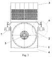
- FIG. 1 can be seen as left and right in the upper part of the static component, here directly on the machine housing 2 of a large electric machine 1 left us right each one Schwingungstilgungs Rhein 6 is arranged to reduce vibration.
- the Schwingungstilger sexualen 6 are symmetrically or diagonally opposite to the machine housing 2 below the level on the radiator 3 is set up as a top cooler arranged.
- the electric machine 1 is a housing storage machine, ie the shaft 5 is mounted in the machine housing 2 on a foundation 4 and is firmly connected thereto.
- the translational vibration damper 7 are mounted opposite to the machine housing 2.
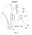
- FIG. 2 shows in detail a Schwingungstilger worn 6 with a novel translational vibration damper7.
- the vibration damper 7 is arranged directly with a suspension device 14 on the machine housing 2, wherein the actually active translational vibration damper 7 by means of one or more chains 15 (other suspensions are possible, for example by means of ropes or support straps or resilient support elements) on a boom of Suspension device 14 is freely movable or pendulum mounted.
- the vibrations of the machine housing 2 are coupled directly by means of the base plate 9 from the machine housing 2 in the translational vibration damper 7.
- the base plate 9 lies directly flat on the machine housing 2 and is firmly connected to the machine housing 2.
- the base plate 9 is screwed or welded. But there are also other fortifications possible in general.
- two, four, six or more bolts 12 are embedded and fixed, which store the spring-mass system 8 and lead.
- the mass 12 is elastically mounted between two spring assemblies, which consist of two opposing prestressed springs 11.
- nuts (threaded nuts on threaded bolts) 13 The exact position of both the mass 12 and the spring preload can be adjusted with the help of bolts 10 highly accurate and adapted to non-linear spring characteristics to the exciter frequency.
- springs preferably coil springs, disc springs or optionally also suitably dimensioned rubber spring elements are used. Due to the coordinated dimensioning of the selection, dimension and characteristics of the springs to be pretensioned 11 and the correspondingly selected mass 12, the tuning frequency can be precisely determined.
- the vote is to be chosen so that at excitation frequency, a phase ratio of preferably 85 ° to 95 ° between the base plate 9 and mass 12 is set.
- a chain 15 is attached to the oscillating suspension, which is attached via an arbitrarily executable suspension device 14 on the machine housing 2.
- FIG. 3 shows a side view of an electric machine 1, ie a housing storage machine and the arrangement of a Schwingungstilgungs worn 6 on the machine housing 2 above flush with the machine housing 2 in the direction of the bearing 5 of the electric machine 1.
- the translational vibration damper 7 is here in this example with six bolts 12th executed on the base plate 9 and guided and attached to this.
- the number of bolts 12 is dependent on the required dimensions of the mass 12 and the required vote of the spring-mass system 8.
- the number of bolts 10 can be determined by the selected type of springs or by the spring constant.
- the spring-mass system 8 is once again depicted for a somewhat smaller sized large electrical machine.
- the spring-mass system 8 is mounted and guided on two times three bolts 10 and fixed by means of the base plate 9 on the machine housing 2 for vibration coupling. It is composed for example per bolt 10 of a resilient rubber element 11 and a counter-acting prestressable coil spring 11, which store the mass 12 swinging between the lockable nuts 13, lead and dampen the coupled vibrations.
Landscapes
- Engineering & Computer Science (AREA)
- General Engineering & Computer Science (AREA)
- Mechanical Engineering (AREA)
- Motor Or Generator Frames (AREA)
- Vibration Prevention Devices (AREA)
Applications Claiming Priority (1)
| Application Number | Priority Date | Filing Date | Title |
|---|---|---|---|
| DE102011053730A DE102011053730A1 (de) | 2011-09-16 | 2011-09-16 | Schwingungstilgungseinrichtung für eine große elektrische Maschine |
Publications (2)
| Publication Number | Publication Date |
|---|---|
| EP2570697A2 true EP2570697A2 (fr) | 2013-03-20 |
| EP2570697A3 EP2570697A3 (fr) | 2017-11-08 |
Family
ID=46963477
Family Applications (1)
| Application Number | Title | Priority Date | Filing Date |
|---|---|---|---|
| EP12184344.5A Withdrawn EP2570697A3 (fr) | 2011-09-16 | 2012-09-13 | Dispositif d'amortissement d'oscillations pour une grande machine électrique |
Country Status (2)
| Country | Link |
|---|---|
| EP (1) | EP2570697A3 (fr) |
| DE (1) | DE102011053730A1 (fr) |
Cited By (4)
| Publication number | Priority date | Publication date | Assignee | Title |
|---|---|---|---|---|
| CN107059743A (zh) * | 2017-06-26 | 2017-08-18 | 佛山科学技术学院 | 一种降噪的道路施工装置 |
| WO2019020947A1 (fr) | 2017-07-26 | 2019-01-31 | Jes Labs | Installation et procede de gestion de donnees de produits |
| CN112421843A (zh) * | 2020-11-27 | 2021-02-26 | 湖南科宏特泵业有限公司 | 一种用于放置电机的便携承载架 |
| CN118694079A (zh) * | 2024-08-29 | 2024-09-24 | 台州环洋机电有限公司 | 一种发电机减震机构 |
Families Citing this family (2)
| Publication number | Priority date | Publication date | Assignee | Title |
|---|---|---|---|---|
| CN111277073B (zh) * | 2018-12-04 | 2022-10-04 | 青岛海尔洗碗机有限公司 | 一种减振电机安装结构及洗碗机 |
| CN112283288B (zh) * | 2020-11-26 | 2022-07-19 | 电子科技大学中山学院 | 一种新能源汽车电驱装置 |
Citations (1)
| Publication number | Priority date | Publication date | Assignee | Title |
|---|---|---|---|---|
| DE10150031A1 (de) | 2001-10-12 | 2003-04-17 | Wunnibald Kunz | Einphasiger elektrischer Antriebsmotor mit Einrichtungen zur Minderung der Schwingungs- und Schallerzeugung |
Family Cites Families (5)
| Publication number | Priority date | Publication date | Assignee | Title |
|---|---|---|---|---|
| DE878737C (de) * | 1951-02-09 | 1953-06-05 | Licentia Gmbh | Kompensator fuer mechanische Schwingsysteme, die erzwungene Schwingungen ausfuehren |
| US3388772A (en) * | 1966-06-16 | 1968-06-18 | Continental Motors Corp | Vibration absorber |
| DE10062369A1 (de) * | 2000-12-14 | 2002-06-20 | Bsh Bosch Siemens Hausgeraete | Anordnung zur Dämpfung der von einem Motor ausgehenden Schwingungen |
| DE10062370A1 (de) * | 2000-12-14 | 2002-06-20 | Bsh Bosch Siemens Hausgeraete | Anordnung zur Dämpfung der von einem Motor ausgehenden Schwingung |
| CN101943242B (zh) * | 2006-03-27 | 2012-10-03 | 三井造船株式会社 | 动态阻尼器及设置有动态阻尼器的柴油机 |
-
2011
- 2011-09-16 DE DE102011053730A patent/DE102011053730A1/de not_active Withdrawn
-
2012
- 2012-09-13 EP EP12184344.5A patent/EP2570697A3/fr not_active Withdrawn
Patent Citations (1)
| Publication number | Priority date | Publication date | Assignee | Title |
|---|---|---|---|---|
| DE10150031A1 (de) | 2001-10-12 | 2003-04-17 | Wunnibald Kunz | Einphasiger elektrischer Antriebsmotor mit Einrichtungen zur Minderung der Schwingungs- und Schallerzeugung |
Cited By (4)
| Publication number | Priority date | Publication date | Assignee | Title |
|---|---|---|---|---|
| CN107059743A (zh) * | 2017-06-26 | 2017-08-18 | 佛山科学技术学院 | 一种降噪的道路施工装置 |
| WO2019020947A1 (fr) | 2017-07-26 | 2019-01-31 | Jes Labs | Installation et procede de gestion de donnees de produits |
| CN112421843A (zh) * | 2020-11-27 | 2021-02-26 | 湖南科宏特泵业有限公司 | 一种用于放置电机的便携承载架 |
| CN118694079A (zh) * | 2024-08-29 | 2024-09-24 | 台州环洋机电有限公司 | 一种发电机减震机构 |
Also Published As
| Publication number | Publication date |
|---|---|
| DE102011053730A1 (de) | 2013-03-21 |
| EP2570697A3 (fr) | 2017-11-08 |
Similar Documents
| Publication | Publication Date | Title |
|---|---|---|
| EP1008747B1 (fr) | Amortisseur de vibration pour éoliennes | |
| EP2570697A2 (fr) | Dispositif d'amortissement d'oscillations pour une grande machine électrique | |
| EP3227579B1 (fr) | Amortisseur de vibrations adaptatif muni d'un système de ressort | |
| DE2603688C3 (de) | Anordnung zum Schwingungsausgleich | |
| EP3243011B1 (fr) | Désaccouplement actif élastique double intégré | |
| DE102010015160A1 (de) | Turmschwingungsdämpfer für eine Windenergieanlage und Windenergieanlage | |
| EP2673531A1 (fr) | Montage sans vibrations d'un objet sur une structure | |
| EP3899266B1 (fr) | Amortisseur de vibrations d'impulsions pour structures élancées élevées | |
| EP2525476B1 (fr) | Système d'isolateur à l'découplage du bruit d'impact pour une grande machine électrique | |
| EP3397423B1 (fr) | Amortissement d'oscillations d'une machine-outil | |
| DE102017104733A1 (de) | Fliehkraftpendel mit permanenter Reibung | |
| EP3698067A1 (fr) | Amortisseur de vibration, en particulier pour une armoire de distribution | |
| DE102008052424B4 (de) | Vibrationstilgersystem | |
| DE930731C (de) | Befestigung moeglichst erschuetterungsfrei anzubringender Hilfsgeraete auf Kraftfahrzeugen, insbesondere von elektrischen Batterien auf Ackerschleppern | |
| DE4227992C2 (de) | Stützelement für ein schwingungsbelastetes Aggregat | |
| DE102006044320A1 (de) | Vorrichtung und Verfahren zur aktiven Lagerung einer Antriebseinheit für ein Fahrzeug | |
| DE202016005517U1 (de) | Vorrichtungen und Anlagen mit elastischem Unwuchtantrieb zur Modifizierung von Schwingungszuständen | |
| EP3085986B1 (fr) | Dispositif d'amortisseur d'oscillations | |
| DE102014220293B4 (de) | Schwingungsvorrichtung und Verfahren zur Abstimmung derselben | |
| DE202015002359U1 (de) | Schwingungsisolator | |
| DE202013104449U1 (de) | Schwingungsisolator | |
| EP3848613A1 (fr) | Machine électrique fixée de manière élastique sur un cadre de construction | |
| DE102014003524A1 (de) | Gerät mit Schwingungserfassung | |
| EP3976990B1 (fr) | Amortisseur d'impulsion pour constructions et installations minces et hautes | |
| AT510834B1 (de) | Stromerzeugungsvorrichtung, insbesondere range extender für ein kraftfahrzeug |
Legal Events
| Date | Code | Title | Description |
|---|---|---|---|
| PUAI | Public reference made under article 153(3) epc to a published international application that has entered the european phase |
Free format text: ORIGINAL CODE: 0009012 |
|
| AK | Designated contracting states |
Kind code of ref document: A2 Designated state(s): AL AT BE BG CH CY CZ DE DK EE ES FI FR GB GR HR HU IE IS IT LI LT LU LV MC MK MT NL NO PL PT RO RS SE SI SK SM TR |
|
| AX | Request for extension of the european patent |
Extension state: BA ME |
|
| PUAL | Search report despatched |
Free format text: ORIGINAL CODE: 0009013 |
|
| AK | Designated contracting states |
Kind code of ref document: A3 Designated state(s): AL AT BE BG CH CY CZ DE DK EE ES FI FR GB GR HR HU IE IS IT LI LT LU LV MC MK MT NL NO PL PT RO RS SE SI SK SM TR |
|
| AX | Request for extension of the european patent |
Extension state: BA ME |
|
| RIC1 | Information provided on ipc code assigned before grant |
Ipc: F16F 7/104 20060101AFI20171004BHEP |
|
| STAA | Information on the status of an ep patent application or granted ep patent |
Free format text: STATUS: THE APPLICATION HAS BEEN PUBLISHED |
|
| STAA | Information on the status of an ep patent application or granted ep patent |
Free format text: STATUS: THE APPLICATION IS DEEMED TO BE WITHDRAWN |
|
| 18D | Application deemed to be withdrawn |
Effective date: 20180404 |