EP2570730A2 - System und Verfahren zur Steuerung der Verbrennungsinstabilitäten in Gasturbinensystemen - Google Patents
System und Verfahren zur Steuerung der Verbrennungsinstabilitäten in Gasturbinensystemen Download PDFInfo
- Publication number
- EP2570730A2 EP2570730A2 EP12183780A EP12183780A EP2570730A2 EP 2570730 A2 EP2570730 A2 EP 2570730A2 EP 12183780 A EP12183780 A EP 12183780A EP 12183780 A EP12183780 A EP 12183780A EP 2570730 A2 EP2570730 A2 EP 2570730A2
- Authority
- EP
- European Patent Office
- Prior art keywords
- fuel
- combustor
- section
- gas turbine
- air
- Prior art date
- Legal status (The legal status is an assumption and is not a legal conclusion. Google has not performed a legal analysis and makes no representation as to the accuracy of the status listed.)
- Withdrawn
Links
- 238000002485 combustion reaction Methods 0.000 title claims abstract description 36
- 238000000034 method Methods 0.000 title claims abstract description 15
- 239000000203 mixture Substances 0.000 claims abstract description 45
- 239000007789 gas Substances 0.000 claims description 76
- 239000000446 fuel Substances 0.000 claims description 57
- 239000011261 inert gas Substances 0.000 claims description 10
- 238000004891 communication Methods 0.000 claims description 7
- 239000012530 fluid Substances 0.000 claims description 6
- 230000001276 controlling effect Effects 0.000 description 11
- 230000008878 coupling Effects 0.000 description 4
- 238000010168 coupling process Methods 0.000 description 4
- 238000005859 coupling reaction Methods 0.000 description 4
- 230000003247 decreasing effect Effects 0.000 description 4
- VNWKTOKETHGBQD-UHFFFAOYSA-N methane Chemical compound C VNWKTOKETHGBQD-UHFFFAOYSA-N 0.000 description 4
- 239000002737 fuel gas Substances 0.000 description 3
- 238000012544 monitoring process Methods 0.000 description 3
- XKRFYHLGVUSROY-UHFFFAOYSA-N Argon Chemical compound [Ar] XKRFYHLGVUSROY-UHFFFAOYSA-N 0.000 description 2
- IJGRMHOSHXDMSA-UHFFFAOYSA-N Atomic nitrogen Chemical compound N#N IJGRMHOSHXDMSA-UHFFFAOYSA-N 0.000 description 2
- 230000001133 acceleration Effects 0.000 description 2
- UQMRAFJOBWOFNS-UHFFFAOYSA-N butyl 2-(2,4-dichlorophenoxy)acetate Chemical compound CCCCOC(=O)COC1=CC=C(Cl)C=C1Cl UQMRAFJOBWOFNS-UHFFFAOYSA-N 0.000 description 2
- 230000008859 change Effects 0.000 description 2
- 238000011161 development Methods 0.000 description 2
- 238000010438 heat treatment Methods 0.000 description 2
- 229930195733 hydrocarbon Natural products 0.000 description 2
- 150000002430 hydrocarbons Chemical class 0.000 description 2
- 239000001257 hydrogen Substances 0.000 description 2
- 229910052739 hydrogen Inorganic materials 0.000 description 2
- 125000004435 hydrogen atom Chemical class [H]* 0.000 description 2
- 239000007788 liquid Substances 0.000 description 2
- 238000012986 modification Methods 0.000 description 2
- 230000004048 modification Effects 0.000 description 2
- 239000003345 natural gas Substances 0.000 description 2
- 239000003921 oil Substances 0.000 description 2
- 238000010248 power generation Methods 0.000 description 2
- 230000009467 reduction Effects 0.000 description 2
- 238000011144 upstream manufacturing Methods 0.000 description 2
- 229910052786 argon Inorganic materials 0.000 description 1
- 238000003491 array Methods 0.000 description 1
- 230000001413 cellular effect Effects 0.000 description 1
- 230000002596 correlated effect Effects 0.000 description 1
- 238000010586 diagram Methods 0.000 description 1
- 230000000694 effects Effects 0.000 description 1
- 239000001307 helium Substances 0.000 description 1
- 229910052734 helium Inorganic materials 0.000 description 1
- SWQJXJOGLNCZEY-UHFFFAOYSA-N helium atom Chemical compound [He] SWQJXJOGLNCZEY-UHFFFAOYSA-N 0.000 description 1
- 238000002347 injection Methods 0.000 description 1
- 239000007924 injection Substances 0.000 description 1
- 229910052743 krypton Inorganic materials 0.000 description 1
- DNNSSWSSYDEUBZ-UHFFFAOYSA-N krypton atom Chemical compound [Kr] DNNSSWSSYDEUBZ-UHFFFAOYSA-N 0.000 description 1
- 238000005259 measurement Methods 0.000 description 1
- 229910052754 neon Inorganic materials 0.000 description 1
- GKAOGPIIYCISHV-UHFFFAOYSA-N neon atom Chemical compound [Ne] GKAOGPIIYCISHV-UHFFFAOYSA-N 0.000 description 1
- 229910052757 nitrogen Inorganic materials 0.000 description 1
- 230000003287 optical effect Effects 0.000 description 1
- 230000010355 oscillation Effects 0.000 description 1
- 229910052704 radon Inorganic materials 0.000 description 1
- SYUHGPGVQRZVTB-UHFFFAOYSA-N radon atom Chemical compound [Rn] SYUHGPGVQRZVTB-UHFFFAOYSA-N 0.000 description 1
- 238000011084 recovery Methods 0.000 description 1
- 238000012552 review Methods 0.000 description 1
- 210000003954 umbilical cord Anatomy 0.000 description 1
- XLYOFNOQVPJJNP-UHFFFAOYSA-N water Substances O XLYOFNOQVPJJNP-UHFFFAOYSA-N 0.000 description 1
- 229910052724 xenon Inorganic materials 0.000 description 1
- FHNFHKCVQCLJFQ-UHFFFAOYSA-N xenon atom Chemical compound [Xe] FHNFHKCVQCLJFQ-UHFFFAOYSA-N 0.000 description 1
Images


Classifications
-
- F—MECHANICAL ENGINEERING; LIGHTING; HEATING; WEAPONS; BLASTING
- F23—COMBUSTION APPARATUS; COMBUSTION PROCESSES
- F23R—GENERATING COMBUSTION PRODUCTS OF HIGH PRESSURE OR HIGH VELOCITY, e.g. GAS-TURBINE COMBUSTION CHAMBERS
- F23R3/00—Continuous combustion chambers using liquid or gaseous fuel
- F23R3/42—Continuous combustion chambers using liquid or gaseous fuel characterised by the arrangement or form of the flame tubes or combustion chambers
- F23R3/46—Combustion chambers comprising an annular arrangement of several essentially tubular flame tubes within a common annular casing or within individual casings
-
- F—MECHANICAL ENGINEERING; LIGHTING; HEATING; WEAPONS; BLASTING
- F23—COMBUSTION APPARATUS; COMBUSTION PROCESSES
- F23C—METHODS OR APPARATUS FOR COMBUSTION USING FLUID FUEL OR SOLID FUEL SUSPENDED IN A CARRIER GAS OR AIR
- F23C9/00—Combustion apparatus characterised by arrangements for returning combustion products or flue gases to the combustion chamber
-
- F—MECHANICAL ENGINEERING; LIGHTING; HEATING; WEAPONS; BLASTING
- F23—COMBUSTION APPARATUS; COMBUSTION PROCESSES
- F23L—SUPPLYING AIR OR NON-COMBUSTIBLE LIQUIDS OR GASES TO COMBUSTION APPARATUS IN GENERAL ; VALVES OR DAMPERS SPECIALLY ADAPTED FOR CONTROLLING AIR SUPPLY OR DRAUGHT IN COMBUSTION APPARATUS; INDUCING DRAUGHT IN COMBUSTION APPARATUS; TOPS FOR CHIMNEYS OR VENTILATING SHAFTS; TERMINALS FOR FLUES
- F23L7/00—Supplying non-combustible liquids or gases, other than air, to the fire, e.g. oxygen, steam
-
- F—MECHANICAL ENGINEERING; LIGHTING; HEATING; WEAPONS; BLASTING
- F23—COMBUSTION APPARATUS; COMBUSTION PROCESSES
- F23N—REGULATING OR CONTROLLING COMBUSTION
- F23N5/00—Systems for controlling combustion
- F23N5/003—Systems for controlling combustion using detectors sensitive to combustion gas properties
-
- F—MECHANICAL ENGINEERING; LIGHTING; HEATING; WEAPONS; BLASTING
- F23—COMBUSTION APPARATUS; COMBUSTION PROCESSES
- F23R—GENERATING COMBUSTION PRODUCTS OF HIGH PRESSURE OR HIGH VELOCITY, e.g. GAS-TURBINE COMBUSTION CHAMBERS
- F23R3/00—Continuous combustion chambers using liquid or gaseous fuel
- F23R3/02—Continuous combustion chambers using liquid or gaseous fuel characterised by the air-flow or gas-flow configuration
- F23R3/16—Continuous combustion chambers using liquid or gaseous fuel characterised by the air-flow or gas-flow configuration with devices inside the flame tube or the combustion chamber to influence the air or gas flow
-
- F—MECHANICAL ENGINEERING; LIGHTING; HEATING; WEAPONS; BLASTING
- F23—COMBUSTION APPARATUS; COMBUSTION PROCESSES
- F23R—GENERATING COMBUSTION PRODUCTS OF HIGH PRESSURE OR HIGH VELOCITY, e.g. GAS-TURBINE COMBUSTION CHAMBERS
- F23R3/00—Continuous combustion chambers using liquid or gaseous fuel
- F23R3/28—Continuous combustion chambers using liquid or gaseous fuel characterised by the fuel supply
-
- F—MECHANICAL ENGINEERING; LIGHTING; HEATING; WEAPONS; BLASTING
- F23—COMBUSTION APPARATUS; COMBUSTION PROCESSES
- F23N—REGULATING OR CONTROLLING COMBUSTION
- F23N2221/00—Pretreatment or prehandling
- F23N2221/12—Recycling exhaust gases
-
- F—MECHANICAL ENGINEERING; LIGHTING; HEATING; WEAPONS; BLASTING
- F23—COMBUSTION APPARATUS; COMBUSTION PROCESSES
- F23N—REGULATING OR CONTROLLING COMBUSTION
- F23N2225/00—Measuring
- F23N2225/26—Measuring humidity
-
- F—MECHANICAL ENGINEERING; LIGHTING; HEATING; WEAPONS; BLASTING
- F23—COMBUSTION APPARATUS; COMBUSTION PROCESSES
- F23N—REGULATING OR CONTROLLING COMBUSTION
- F23N2237/00—Controlling
- F23N2237/02—Controlling two or more burners
-
- F—MECHANICAL ENGINEERING; LIGHTING; HEATING; WEAPONS; BLASTING
- F23—COMBUSTION APPARATUS; COMBUSTION PROCESSES
- F23N—REGULATING OR CONTROLLING COMBUSTION
- F23N2241/00—Applications
- F23N2241/20—Gas turbines
-
- F—MECHANICAL ENGINEERING; LIGHTING; HEATING; WEAPONS; BLASTING
- F23—COMBUSTION APPARATUS; COMBUSTION PROCESSES
- F23R—GENERATING COMBUSTION PRODUCTS OF HIGH PRESSURE OR HIGH VELOCITY, e.g. GAS-TURBINE COMBUSTION CHAMBERS
- F23R2900/00—Special features of, or arrangements for continuous combustion chambers; Combustion processes therefor
- F23R2900/00013—Reducing thermo-acoustic vibrations by active means
Definitions
- the present disclosure is generally related to gas turbine systems, and more particularly to systems and methods for controlling combustion instabilities in gas turbine systems.
- a conventional gas turbine system includes a compressor section, a combustor section, and a turbine section.
- compressed air is provided from the compressor section to the combustor section.
- the air entering the combustor section is mixed with fuel and combusted. Hot gases of combustion flow from the combustor section to the turbine section to drive the gas turbine system and generate power.
- a gas turbine system in one aspect, includes a compressor section, a turbine section connected to the compressor section, and a combustor section connected to the compressor section and the turbine section.
- the combustor section includes a plurality of combustors, each of the plurality of combustors including an outer shell defining a chamber therein.
- Each of plurality of combustors is in fluid communication with the compressor section for flowing air to each of the plurality of chambers and further includes at least one injector for injecting a fuel into the chamber such that the air and fuel form an air-fuel mixture.
- the combustor section further includes at least one igniter for igniting the fuel-air mixture within each of the plurality of combustors into a hot gas.
- the gas turbine system further includes a control system for controlling a velocity of the hot gas in at least one of the plurality of combustors by controlling an operating parameter of the fuel-air mixture.
- a method for controlling combustion instability in a combustion section of a gas turbine system includes determining a velocity of a hot gas in a combustor of the combustion section, and adjusting an operating parameter of the fuel-air mixture.
- the combustor includes an outer shell defining a chamber therein.
- the combustor is in fluid communication with a compressor section of the turbine system for flowing air to the chamber and further includes at least one injector for injecting a fuel into the chamber such that the air and fuel form an air-fuel mixture.
- the combustor section further includes at least one igniter for igniting the fuel-air mixture within the combustor into the hot gas.
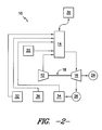
- FIGS. 1 and 2 are schematic diagrams of various embodiments of a gas turbine system 10.
- the system 10 may include a compressor section 12, a combustor section 14, and a turbine section 16.
- the compressor section 12 and turbine section 16 may be coupled by a shaft 18.
- the shaft 18 may be a single shaft or a plurality of shaft segments coupled together to form shaft 18.
- the combustor section 14 of a gas turbine system 10 may include a plurality of combustors 20, also known as combustor cans, (one of which is shown in each of FIGS. 3 through 7 ).
- the combustors 20 are positioned in an annular array about a central axis.
- air and fuel may be provided to each of the combustors 20 and mixed therein.
- Igniters (not shown) positioned in or adjacent to one or more of the combustors 20 may ignite the air-fuel mixture, causing combustion thereof into a hot gas.
- Air is typically provided to the combustor section 14 from the compressor section 12 after being compressed, as is generally known in the art.
- Fuel may be provided to each of the combustors 20 in the combustor section from a fuel source 22.
- the fuel source may be any suitable source that provides a suitable fuel to the system 10.
- Suitable fuels according to the prevent disclosure include any suitable gas or liquid fuels, such as natural gas or an oil. Further, suitable fuels include fuels and fuel compositions that may be utilized in flexible fuel gas turbine systems, such as fuel compositions including hydrogen, relatively high amounts of hydrocarbons, and/or having relatively high lower heating values.
- the system 10 may further include a generator 24. Power generated through operation of the compressor section 12, combustor section 14, and turbine section 16 is provided to and stored in the generator 24.
- the generator 24 is coupled to the compressor section 12 and turbine section 16 by the shaft 18. Exhaust gases may be exhausted into the atmosphere, to a suitable heat exchanger such as a heat recovery steam generator (“HRSG”) 26 as shown, or to any other suitable device or apparatus.
- HRSG heat recovery steam generator
- the gas turbine system 10 further includes various devices and apparatus for controlling combustion instabilities, such as combustion noise, flashback and/or flame holding. Control of such combustion instabilities will allow for reduction and control of the occurrences of the instabilities, thus allowing for safer operation of the system 10.
- combustion instabilities such as combustion noise, flashback and/or flame holding. Control of such combustion instabilities will allow for reduction and control of the occurrences of the instabilities, thus allowing for safer operation of the system 10.
- the present system 10 further includes a control system 30.
- the control system 30 controls the velocity of the combusted hot gas in one or more of the plurality of combustors 20.
- the present inventors have discovered that control of the velocity of such hot gases advantageously allows for control of combustion instabilities.
- control of the velocity of the hot gas may further control various parameters of the hot gas flow that contribute to combustion instabilities, such as amplitude, frequency, and rate of change of combustion oscillations.
- control of the velocity of the hot gas is practical, efficient, and effective for controlling and minimizing combustion instabilities in a system 10.
- the control system 30 may be communicatively coupled to the combustor section 14, and one or more combustors thereof, for controlling the velocity of combusted hot gases.
- the communicative coupling may be through a physical coupling, such as through a wire or other conduit or umbilical cord, or may be a wireless coupling, such as through an infra-red, cellular, sonic, optical, or radio frequency based coupling.
- the control system 30 may include a processor and suitable hardware and software for monitoring and controlling the velocity of a hot gas.
- the control system may be fully or partially manually operated, and/or may be fully or partially automated through the use of such hardware and software, such as suitable programming logic.
- the control system 30 may be included in a computer or other device suitable for operation of the control system 30.
- the control system 30 controls the velocity of the hot gas in one or more of the plurality of combustors by controlling one or more operating parameters of the fuel-air mixture.
- the control system 30 includes hardware and software for monitoring the velocity of the hot gas, monitoring an operating parameter, and adjusting the operating parameter, as discussed.
- Such hardware and software may include sensors and other suitable measurement devices as well as suitable programs for calculating hot gas velocity, various parameters, and changes thereof.
- an operating parameter may be fuel-air ratio.
- the amount of fuel and/or the amount of air being provided to a combustor 20 to form the fuel-air mixture may be adjusted by the control system 30 as required to adjust the velocity of the hot gas in the combustor.
- the amount of fuel supplied could be increased or decreased and/or the amount of air supplied could be increased or decreased as required.
- an operating parameter may be fuel-air mixture composition.
- the composition of the fuel being provided to a combustor 20 to form the fuel-air mixture may be adjusted by the control system 30 as required to adjust the velocity of the hot gas in the combustor.
- the amount of natural gas, oil, hydrogen, fuels containing relatively high amounts of hydrocarbons, fuels having relatively high lower heating values, and/or other suitable liquids or gases that make up the fuel may be increased or decreased as required.
- an operating parameter may be fuel-air mixture velocity.
- the velocity of the fuel, the air, or the combined fuel-air mixture may be adjusted by the control system 30 as required to adjust the velocity of the hot gas in the combustor.
- the velocity of the fuel, the air, or the combined fuel-air mixture may be increased or decreased as required.
- an operating parameter may be turbine load, exhaust gas temperature, exhaust gas composition, compressor air pressure, compressor temperature, combustion temperature, combustion noise frequency, combustion noise amplitude, combustion noise velocity, and/or combustion noise acceleration.
- the operating parameters of the present disclosure are not limited to the above disclosed examples, and rather that any suitable operating parameter of the fuel-air mixture that may be correlated to the velocity of the hot gas in a combustor 20 and adjusted to adjust the velocity of the hot gas in a combustor 20 are within the scope and spirit of the present disclosure.
- the system 10 may further include various devices connected to the combustor section 20 to adjust one or more operating parameters as required by the control system 30. Each device is thus communicatively coupled to the control system 30 and controlled thereby.
- the system 10 may include a humidifier 32.
- the humidifier 32 may be connected to the fuel source 22 and/or to the air flowing from the compressor 12 to the combustor 14, as shown in FIG. 1 , and/or directly to the combustor section 14 as shown in FIG. 2 .
- the humidifier 32 may be directly connected to one or more injectors, or through the outer casing, discussed below, or otherwise, of one or more of combustors 20.
- the humidifier 32 may add water and/or steam to the air-fuel mixture as desired or required to adjust an operating parameter thereof.
- the system 10 may include an exhaust gas recirculation device 34.
- the exhaust gas recirculation device 34 may be connected to the fuel source 22, as shown in FIG. 1 , and/or directly to the combustor section 14 as shown in FIG. 2 .
- the exhaust gas recirculation device 34 may be directly connected to one or more injectors, or through the outer casing, discussed below, or otherwise, of one or more of combustors 20.
- the exhaust gas recirculation device 34 may further be connected to a HRSG 26, or may be directly connected to the exhaust from the generator 24.
- the exhaust gas recirculation device 34 may add exhaust gas exhausted from the generator 24 to the air-fuel mixture as desired or required to adjust an operating parameter thereof.
- the system 10 may include an inert gas circulation device 36.
- the inert gas circulation device 36 may be connected to the fuel source 22, as shown in FIG. 1 , and/or directly to the combustor section 14 as shown in FIG. 2 .
- the inert gas circulation device 36 may be directly connected to one or more injectors, or through the outer casing, discussed below, or otherwise, of one or more of combustors 20.
- the inert gas circulation device 36 may add an inert gas, such as helium, neon, argon, krypton, xenon, radon, sulfer, hexaflouride, nitrogen, or any other suitable inert gas, to the air-fuel mixture as desired or required to adjust an operating parameter thereof.
- an inert gas such as helium, neon, argon, krypton, xenon, radon, sulfer, hexaflouride, nitrogen, or any other suitable inert gas
- a combustor 20 may include an outer shell 40 defining a chamber 42 therein.
- a combustor 20 may further include one or more injectors 44. Each injector 44 injects a fuel into the chamber 42.
- each injector 44 may be connected to the outer shell 40 and extend therethrough, and further connected to the fuel source 22, thus placing the fuel source 22 and combustor in fluid communication for flowing fuel therethrough.
- each injector 44 into the chamber 42 of a combustor 20 may have a composition and/or velocity that is identical to or different from those of any other injectors 44 in the combustor 20 and/or combustion section 14.
- a combustor 20 may include a plurality of injectors 44.
- One or more of the injectors 44 may be positioned adjacent to an inlet 46 of the combustor 20.
- Another one or more of the injectors 44 may be downstream injectors 48, which are injectors positioned downstream of the inlet 46 to provide late injection of fuel into the combustor 20.
- a combustor 20 according to the present disclosure may further be in fluid communication with the compressor section 12 for flowing air to each of the plurality of chambers 42.
- the outer casing 40 or other suitable component of the combustor 20 may define one or more apertures 50.
- the apertures 50 may allow air flowing from the compressor 12 through a plenum 52 surrounding the combustor 20 therethrough and into the chamber 42 for mixing with the fuel to form a fuel-air mixture.
- a combustor 20 may further advantageously include a plurality of venturi nozzles 60.
- a venturi nozzle 60 is a nozzle that includes a restricted portion 62 as well as an upstream portion 64 and/or a downstream portion 66. Further upstream portion 64 and/or downstream portion 66 generally taper to the restricted portion 62 such that the restricted portion has a generally smaller cross-sectional area, thus causing a flow therethrough to have a lower pressure and higher velocity within the restricted portion.
- Each venturi nozzle 60 is positioned in the combustor 20, such as at least partially in the chamber 42 of the combustor 20, for flowing fuel, air, or the fuel-air mixture therethrough.
- a venturi nozzle 60 may be coupled to an injector 44 for flowing fuel therethrough, or may be positioned adjacent to one or more apertures for flowing air therethrough, or may be generally positioned within a chamber 42 for flowing a fuel-air mixture therethrough.
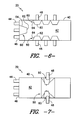
- venturi nozzles 60 may be arranged in an annular array, such as generally about the circumference of the chamber 42 as shown in FIGS. 4 , 6 and 7 .
- One or more of the annular array of venturi nozzles 60 may be coupled to an injector 44, such as an injector 44 adjacent inlet 46 or a downstream injector 48, and may thus flow fuel therethrough.
- one or more of the annular array of venturi nozzles 60 may be coupled to an aperture 50 and may thus flow air therethrough.
- venturi nozzles 60 are arranged in an axial array, such as along a portion of the chamber 42 as shown in FIGS. 5 and 6 .
- One or more of the axial array of venturi nozzles 60 may be coupled to an injector 44, such as an injector adjacent inlet 46 or a downstream injector 48, and may thus flow fuel therethrough.
- one or more of the axial array of venturi nozzles 60 may be coupled to an aperture 50 and may thus flow air therethrough.
- FIG. 4 illustrates a plurality of venturi nozzles 60 arranged in an annular array adjacent inlet 46.
- One or more of these venturi nozzles 60 may be coupled to an injector 48.
- An additional venturi nozzle 60 is positioned downstream of this annular array, as shown. This venturi nozzle 60 flows fuel and/or air within the chamber 42 therethrough.
- FIG. 5 illustrates a plurality of venturi nozzles 60 arranged in an axial array.
- One venturi nozzle 60 may be positioned adjacent inlet 46, and may be coupled to an injector 48. Another is positioned downstream, as shown. This venturi nozzle 60 flows fuel and/or air within the chamber 42 therethrough.
- FIG. 6 illustrates a plurality of venturi nozzles 60 arranged in annular and axial arrays.
- One venturi nozzle 60 may be positioned adjacent inlet 46, and may be coupled to an injector 48.
- Others are positioned downstream, and may be coupled to downstream injectors 48.
- FIG. 7 illustrates a plurality of venturi nozzles 60 arranged in an annular array. Various of these may be coupled to downstream injector 48. An additional venturi nozzle 60 may be positioned downstream and in communication with the annular array, for flowing fuel and/or air within the chamber 42 therethrough.
- the present disclosure is further directed to a method for controlling combustion instability in a combustion section 14 and combustor 20 of a gas turbine system 10.
- the method includes, for example, determining a velocity of a hot gas in the combustor, and adjusting one or more operating parameters of the fuel-air mixture that is provided to the combustor and ignited into the hot gas.
- Such adjustment according to the present disclosure may effect a change in velocity, which may result in control of combustion instabilities, as discussed.
- the operating parameters may include, for example, fuel-to-air ratio, fuel-air mixture composition, fuel-air mixture velocity, turbine load, exhaust gas temperature, exhaust gas composition, compressor air pressure, compressor temperature, combustion temperature, combustion noise frequency, combustion noise amplitude, combustion noise velocity, and/or combustion noise acceleration.
- the adjusting step includes operating a humidifier 32 connected to the combustor section 20, as discussed above. In other embodiments, the adjusting step includes operating an exhaust gas recirculation device 34 connected to the combustor section 20, as discussed above. In still other embodiments, the adjusting step includes operating an inert gas circulation device 36 connected to the combustor section 20, as discussed above.
- a combustor according to the present method includes a plurality of venturi nozzles 60, as discussed above.
Landscapes
- Engineering & Computer Science (AREA)
- Chemical & Material Sciences (AREA)
- Combustion & Propulsion (AREA)
- Mechanical Engineering (AREA)
- General Engineering & Computer Science (AREA)
Applications Claiming Priority (1)
| Application Number | Priority Date | Filing Date | Title |
|---|---|---|---|
| US13/234,493 US20130067927A1 (en) | 2011-09-16 | 2011-09-16 | System and method for controlling combustion instabilities in gas turbine systems |
Publications (1)
| Publication Number | Publication Date |
|---|---|
| EP2570730A2 true EP2570730A2 (de) | 2013-03-20 |
Family
ID=46924277
Family Applications (1)
| Application Number | Title | Priority Date | Filing Date |
|---|---|---|---|
| EP12183780A Withdrawn EP2570730A2 (de) | 2011-09-16 | 2012-09-10 | System und Verfahren zur Steuerung der Verbrennungsinstabilitäten in Gasturbinensystemen |
Country Status (3)
| Country | Link |
|---|---|
| US (1) | US20130067927A1 (de) |
| EP (1) | EP2570730A2 (de) |
| CN (1) | CN102996259A (de) |
Families Citing this family (3)
| Publication number | Priority date | Publication date | Assignee | Title |
|---|---|---|---|---|
| US10480792B2 (en) * | 2015-03-06 | 2019-11-19 | General Electric Company | Fuel staging in a gas turbine engine |
| US11519334B2 (en) * | 2017-07-31 | 2022-12-06 | General Electric Company | Torch igniter for a combustor |
| US20210172376A1 (en) * | 2019-12-10 | 2021-06-10 | General Electric Company | Combustor ignition timing |
Family Cites Families (3)
| Publication number | Priority date | Publication date | Assignee | Title |
|---|---|---|---|---|
| US5927076A (en) * | 1996-10-22 | 1999-07-27 | Westinghouse Electric Corporation | Multiple venturi ultra-low nox combustor |
| WO2005071316A1 (en) * | 2004-01-12 | 2005-08-04 | Combustion Science & Engineering, Inc. | System and method for flame stabilization and control |
| US8381529B2 (en) * | 2009-01-29 | 2013-02-26 | General Electric Company | System and method for water injection in a turbine engine |
-
2011
- 2011-09-16 US US13/234,493 patent/US20130067927A1/en not_active Abandoned
-
2012
- 2012-09-10 EP EP12183780A patent/EP2570730A2/de not_active Withdrawn
- 2012-09-14 CN CN2012103421183A patent/CN102996259A/zh active Pending
Non-Patent Citations (1)
| Title |
|---|
| None |
Also Published As
| Publication number | Publication date |
|---|---|
| CN102996259A (zh) | 2013-03-27 |
| US20130067927A1 (en) | 2013-03-21 |
Similar Documents
| Publication | Publication Date | Title |
|---|---|---|
| KR102622706B1 (ko) | 연소기용 토치 점화기 | |
| US7546736B2 (en) | Methods and apparatus for low emission gas turbine energy generation | |
| US7513100B2 (en) | Systems for low emission gas turbine energy generation | |
| EP2554905B1 (de) | Anordnungen und Vorrichtung im Zusammenhang mit der Integration später Magergemischeinspritzung in Turbinenverbrennungsmotoren | |
| US6826913B2 (en) | Airflow modulation technique for low emissions combustors | |
| CN100552300C (zh) | 用于燃烧器的同心的固定稀释及可变的旁路空气喷射 | |
| JP5544141B2 (ja) | ガスタービンにおける統合型燃焼器−第1段ノズル並びに関連する方法 | |
| JP6219061B2 (ja) | 燃焼器に燃料を供給するためのシステム | |
| CN103375816B (zh) | 用于将燃料供应到燃烧器的系统 | |
| US9010120B2 (en) | Assemblies and apparatus related to integrating late lean injection into combustion turbine engines | |
| KR20050029676A (ko) | 가스 터빈용 향류 연소기 및 NOx 배기가스를감소시키는 방법 | |
| US10288291B2 (en) | Air-shielded fuel injection assembly to facilitate reduced NOx emissions in a combustor system | |
| KR20200142077A (ko) | 가스 터빈의 연소 안정성 개선 시스템 및 방법 | |
| JP2014132214A (ja) | 燃焼器に燃料を供給する燃料噴射器 | |
| CN103629698A (zh) | 用于降低燃烧动态的系统和方法 | |
| CN103629670A (zh) | 用于降低燃烧动态的系统和方法 | |
| JP2013228195A (ja) | 燃焼器に動作流体を供給するためのシステムおよび方法 | |
| JP6800787B2 (ja) | ガスタービン燃焼器及びその制御方法 | |
| JP2014122784A (ja) | 燃焼器に燃料を供給するためのシステム | |
| CN102155738A (zh) | 用于供给燃料的装置与方法 | |
| CN103423772A (zh) | 带有被动供给燃料的预混合鼓风回路的液体筒 | |
| CN105715378A (zh) | 冷却和稀释空气的分开供给 | |
| CN112594734A (zh) | 燃气轮机燃烧器 | |
| US20130067927A1 (en) | System and method for controlling combustion instabilities in gas turbine systems | |
| WO2025049170A1 (en) | Ammonia combustor |
Legal Events
| Date | Code | Title | Description |
|---|---|---|---|
| PUAI | Public reference made under article 153(3) epc to a published international application that has entered the european phase |
Free format text: ORIGINAL CODE: 0009012 |
|
| AK | Designated contracting states |
Kind code of ref document: A2 Designated state(s): AL AT BE BG CH CY CZ DE DK EE ES FI FR GB GR HR HU IE IS IT LI LT LU LV MC MK MT NL NO PL PT RO RS SE SI SK SM TR |
|
| AX | Request for extension of the european patent |
Extension state: BA ME |
|
| STAA | Information on the status of an ep patent application or granted ep patent |
Free format text: STATUS: THE APPLICATION IS DEEMED TO BE WITHDRAWN |
|
| 18D | Application deemed to be withdrawn |
Effective date: 20150331 |