EP2570816A2 - Vorrichtung und Verfahren für verbesserte Shuntstrommessung - Google Patents
Vorrichtung und Verfahren für verbesserte Shuntstrommessung Download PDFInfo
- Publication number
- EP2570816A2 EP2570816A2 EP12183123A EP12183123A EP2570816A2 EP 2570816 A2 EP2570816 A2 EP 2570816A2 EP 12183123 A EP12183123 A EP 12183123A EP 12183123 A EP12183123 A EP 12183123A EP 2570816 A2 EP2570816 A2 EP 2570816A2
- Authority
- EP
- European Patent Office
- Prior art keywords
- shunt
- current
- current shunt
- sensing element
- conductive
- Prior art date
- Legal status (The legal status is an assumption and is not a legal conclusion. Google has not performed a legal analysis and makes no representation as to the accuracy of the status listed.)
- Granted
Links
Images

Classifications
-
- G—PHYSICS
- G01—MEASURING; TESTING
- G01R—MEASURING ELECTRIC VARIABLES; MEASURING MAGNETIC VARIABLES
- G01R1/00—Details of instruments or arrangements of the types included in groups G01R5/00 - G01R13/00 and G01R31/00
- G01R1/20—Modifications of basic electric elements for use in electric measuring instruments; Structural combinations of such elements with such instruments
- G01R1/203—Resistors used for electric measuring, e.g. decade resistors standards, resistors for comparators, series resistors, shunts
Definitions
- the present disclosure relates generally to a current shunt for measuring current in an electrical system, such as in a renewable energy electrical distribution system.
- the present disclosure more particularly relates to an apparatus and method for improved current shunt sensing across a wide range of frequencies.
- a typical current shunt includes the electrical equivalent of a low value resistor placed in series with an electrical system so that all of the current to be measured flows through the current shunt.
- the shunt resistance is typically as low as possible so that use of the current shunt does not affect or change circuit characteristics. The voltage drop across the current shunt is measured to determine the current flowing through the shunt.
- a sensing element that is narrow in width relative to the current shunt is often coupled between the voltage sensing connections for measuring the voltage across the current shunt.
- a typical sensing element may include a narrow wire/conductor or circuit card trace that is coupled to a voltage measurement device for measuring the voltage across the current shunt.
- FIG. 1 illustrates an exemplary known current shunt 100 for high current applications.
- the current shunt 100 includes high current terminals 110 that can be coupled in series with a load through terminal connections 112.
- Current shunt 100 includes a shunt portion 120 having a resistance that is known to a high degree of accuracy.
- Current shunt 100 further includes a pair of separate sensing terminals 125 to measure the voltage across the current shunt 100.
- a sensing element 130 that comprises a narrow trace disposed on a circuit card 135 is coupled between sensing terminals 125.
- Sensing element 130 is coupled to a plug connection 140 for coupling to a suitable voltage measurement device. As shown in FIG. 1 , sensing element 130 has a width that is narrow relative to the current shunt 100.
- the sensing voltage measured by a narrow sensing element is dependent on the current flowing through the current shunt.
- eddy currents caused by the skin effect can result in a non-uniform distribution of the current flow across the current shunt. More particularly, as the frequency of the current flowing through the current shunt increases, a greater portion of the current flows through the edges of the current shunt than at the middle or center of the current shunt. This causes the voltage drop across the edges of the current shunt to be different than the voltage drop across the center of the current shunt.
- a narrow sensing element such as a wire/conductor or narrow trace, typically only accounts for a voltage drop across a portion of the current shunt.
- the narrow sensing element 130 depicted in FIG. 1 will measure a voltage drop primarily attributable to current flowing through the middle of the current shunt 100. Because the current distribution across the current shunt 100 will vary at higher frequencies, measurements made by a narrow sensing element, such as narrow sensing element 130, may be inaccurate.
- the current shunt includes a conductive portion having an upper surface defining a width and a sensing element overlying the upper surface of the conductive portion.
- the sensing element overlies at least a part of the conductive portion and has a width in the range of about 20% to about 100% of the width of the conductive portion.
- the current shunt includes a pair of current terminals couplable in series with the electrical system and a conductive shunt portion between the current terminals having an upper surface defining a surface area.
- the current shunt further includes a pair of sensing terminals and a circuit card mechanically coupled to the pair of sensing terminals.
- the circuit card includes a conductive trace having a surface area that overlies between about 20% to about 100% of the surface area of the conductive shunt portion.
- a further exemplary aspect of the present disclosure is directed to a method.
- the method includes providing a current shunt comprising a conductive portion having an upper surface defining a width; sizing a sensing element used to measure voltage across the conductive portion of the current shunt to have a width in the range of about 20% to about 100% of the width of the conductive portion of the current shunt; and, placing the sensing element over at least a portion of the upper surface of the conductive portion of the current shunt.
- a current shunt according to the present disclosure includes a conductive portion that is placed in series with an electrical system.
- the current shunt includes a sensing element that is used to measure the voltage across the conductive portion of the current shunt.
- a particular aspect of the present disclosure is directed to a current shunt having a sensing element with an increased width relative to the width of the conductive portion of the shunt.
- the width of the sensing element is within about 20% to about 100% of the width of the conductive portion of the current shunt, such as within about 40% to about 100% of the current shunt, such as within about within about 80% to about 100% of the current shunt, and all other sub-ranges therebetween.
- FIG. 2 illustrates a current shunt 200 according to an exemplary embodiment of the present disclosure.
- Current shunt 200 includes a pair of high current terminals 210.
- Current terminals 210 are adapted to be placed in series with an electrical system such that current flows through the current shunt 210.
- Current terminals 210 can be secured or mechanically coupled to the electrical system through one or more terminal connections 212, such as a nut/bolt connection or other suitable connection.
- Current terminals 210 are composed of a conductive material and can have a resistance that is known to a high degree of accuracy. In a particular embodiment, current terminals 210 can be rated for higher currents, such as up to about 1000 A. Those of ordinary skill in the art, using the disclosures provided herein, should understand that the present disclosure is not limited to a current shunt of any particular current rating.
- Current shunt 200 includes a conductive shunt portion 220 coupled between current terminals 210.
- Conductive shunt portion 220 can include one or more conductive plates disposed between current terminals 210.
- Conductive shunt portion 220 is composed of a conductive material having a resistance known to a high degree of accuracy.
- current flows through the conductive shunt portion 220 causing a small voltage drop across the known resistance of the conductive shunt portion 220. This voltage drop can be measured and correlated to a current using the known resistance of the conductive shunt portion 220 to provide a current measurement of the current flowing through the current shunt 200.
- the current shunt 200 includes a pair of sensing terminals 225 and a sensing element 230 disposed between the sensing terminals 225.
- the sensing element 230 is used to measure the voltage drop across the conductive shunt portion 220.
- the sensing element 230 includes a conductor/wire having a width W 2 that approaches the width W 1 of the current shunt. As will be discussed in detail below, this increases the coupling coefficient between the conductive shunt portion 220 and the sensing element 230, leading to improved voltage measurements across the conductive shunt portion 220 across a wide range of frequencies.
- the sensing element depicted in FIG. 2 includes a conductive trace that is located on a circuit card 230 mechanically connected to sensing terminals 225.
- the circuit card 235 is coupled to the sensing terminals 225 such that the sensing element 230 overlies the conductive shunt portion 220.
- the vertical spacing between the circuit card 235 and the upper surface of the conductive shunt portion 220 is between about 1.5 mm and about 4.5 mm.
- a plug connection 240 is provided so that the sensing element 230 is couplable to a voltage measurement device.
- the sensing element 230 has a surface area that approaches the surface area of the upper surface of the conductive shunt portion 220 and a width W 2 that approaches the width W 1 of the current shunt 200. In this manner, the sensing element 230 is able to capture fields generated by any increased current flow at the edges of the current shunt 200 at high frequencies, providing for improved current measurements by the current shunt 200.
- Simulations were performed for a current shunt constructed similarly to the current shunt 200 depicted in FIG. 2 .
- the width of the current shunt was about 110 mm.
- the width of the sensing element was varied from between about 2 mm to about 100 mm.
- the spacing between the sensing element and the conductive shunt was about 3 mm.
- Table 1 below shows the complex impedance matrix for the conductive shunt portion and the sensing element using an Ansoft Maxwell Eddy Current Solver at 100 KHz.
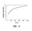
- Table 2 shows the inductive coupling coefficients between the sensing element and the conductive shunt portion at 100 KHz. These values are independent of current flowing through the current shunt.
- Table 2 Sensing Element Width Coupling Coef Conductive Shunt Portion Coupling Coef Sensing Element Coupling Coef Mutual 2 mm 1 1 0.38717 4 mm 1 1 0.44510 8 mm 1 1 0.53697 16 mm 1 1 0.63502 32 mm 1 1 0.73727 100 mm 1 1 0.87595
- the coupling coefficient between the sensing element and the conductive shunt portion increases as the width of the sensing element approaches the width of the current shunt.
- Curve 305 shows that that coupling coefficient between the conductive shunt portion and the sensing element falls within a range of about 0.6 to about 1.0 when the sensing element overlies about 20% to about 100% of the upper surface of the conductive shunt portion.
- the coupling coefficient falls within a range of about 0.7 to about 1.0 when the sensing element overlies about 40% to about 100% of the upper surface of the conductive shunt portion.
- a 20% increase in surface area coverage from about 20% to about 40% results in about a 10% increase in the coupling coefficient between the sensing element and the conductive shunt portion.
- the increase in coupling coefficient allows the sensing element to better capture the fields generated by the current flowing through the current shunt, even at higher frequencies where more current flows at the edges of the current shunt.
- the apparatus and method according to aspects of the present disclosure provide for an improved current shunt sensing across a wide range of frequencies.
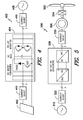
- FIG. 4 illustrates an exemplary solar power distribution system 400.
- Solar power distribution system 400 includes a PV array 402 that supplies power to the electrical grid 406 through solar power converter 404.
- Solar power converter 404 converts DC power generated by PV array 402 into AC power suitable for use with the electrical grid 406.
- the solar power converter 404 illustrated in FIG. 4 is a two-stage solar power converter that includes a DC boost converter coupled to a DC-AC inverter through a DC bus.
- One or more current shunts 410 can be coupled in series with PV array 402 and solar power converter 404 to monitor current flowing from PV array 402 into solar power converter 404.
- One or more current shunts 410 can be coupled in series with the solar power converter 404 and the electrical grid 406 to monitor current flowing from the solar power converter 404 to the electrical grid 406.
- FIG. 5 illustrates an exemplary wind power electrical system 500.
- wind impacts the blades 502 and blades 502 transform wind energy into a mechanical rotational torque that rotatably drives a low-speed shaft.
- the low-speed shaft drives gearbox 504 that subsequently steps up the low rotational speed of low-speed shaft to drive a high-speed shaft at an increased rotational speed.
- the high speed shaft rotatably drives the rotor of generator 506.
- a rotating magnetic field is induced by the rotor of generator 506 and a voltage is induced within the stator of generator 506. In this manner, generator 506 converts the rotational mechanical energy to a sinusoidal, three-phase alternating current (AC) electrical energy signal.
- AC alternating current
- the associated electrical power is provided to an AC-DC-AC converter 508, which is used to supply power to an electrical grid 510.
- One or more current shunts 520 can be coupled in series with generator 506 and AC-DC-AC converter 508 to monitor current flowing from generator 506 to AC-DC-AC converter 508.
- One or more current shunts 520 can also be coupled in series with the AC-DC-AC converter 508 and the electrical grid 510 to monitor current flowing from the AC-DC-AC converter 508 to the electrical grid 510.
Landscapes
- Physics & Mathematics (AREA)
- General Physics & Mathematics (AREA)
- Measuring Instrument Details And Bridges, And Automatic Balancing Devices (AREA)
- Measurement Of Current Or Voltage (AREA)
- Transformers For Measuring Instruments (AREA)
Applications Claiming Priority (1)
| Application Number | Priority Date | Filing Date | Title |
|---|---|---|---|
| US13/235,795 US8981762B2 (en) | 2011-09-19 | 2011-09-19 | Apparatus and method for improved current shunt sensing |
Publications (3)
| Publication Number | Publication Date |
|---|---|
| EP2570816A2 true EP2570816A2 (de) | 2013-03-20 |
| EP2570816A3 EP2570816A3 (de) | 2017-10-25 |
| EP2570816B1 EP2570816B1 (de) | 2023-06-07 |
Family
ID=46982453
Family Applications (1)
| Application Number | Title | Priority Date | Filing Date |
|---|---|---|---|
| EP12183123.4A Active EP2570816B1 (de) | 2011-09-19 | 2012-09-05 | Vorrichtung und Verfahren für verbesserte Shuntstrommessung |
Country Status (5)
| Country | Link |
|---|---|
| US (1) | US8981762B2 (de) |
| EP (1) | EP2570816B1 (de) |
| CN (1) | CN103018516B (de) |
| DK (1) | DK2570816T3 (de) |
| ES (1) | ES2954104T3 (de) |
Cited By (3)
| Publication number | Priority date | Publication date | Assignee | Title |
|---|---|---|---|---|
| CN105372498A (zh) * | 2015-10-29 | 2016-03-02 | 国网山西省电力公司电力科学研究院 | 用于暂态电流测定的分流器阻抗参数确定方法 |
| WO2016131764A1 (de) * | 2015-02-18 | 2016-08-25 | Audi Ag | Elektrische stromschiene mit sensoreinheit |
| WO2017046116A1 (en) * | 2015-09-14 | 2017-03-23 | Carlo Gavazzi Service Ag | Modular measurement system for photovoltaic systems |
Families Citing this family (12)
| Publication number | Priority date | Publication date | Assignee | Title |
|---|---|---|---|---|
| JP6637250B2 (ja) * | 2015-04-28 | 2020-01-29 | Koa株式会社 | 電流検出装置 |
| JP2016206138A (ja) * | 2015-04-28 | 2016-12-08 | Koa株式会社 | 電流検出装置 |
| JP2017015588A (ja) * | 2015-07-02 | 2017-01-19 | Koa株式会社 | 電流検出装置 |
| CN106093523A (zh) * | 2016-06-21 | 2016-11-09 | 福建省计量科学研究院 | 一种i‑v变换器 |
| WO2018109726A1 (en) * | 2016-12-14 | 2018-06-21 | Sendyne Corporation | Compensating for the skin effect in a current shunt |
| CN106771500B (zh) * | 2017-01-22 | 2019-06-21 | 中国南方电网有限责任公司超高压输电公司检修试验中心 | 一种高压直流输电系统不同通道电流量差异性检测方法 |
| US10527653B2 (en) * | 2017-03-30 | 2020-01-07 | Ford Global Technologies, Llc | Ultra-high bandwidth current shunt |
| CN107356788B (zh) * | 2017-07-06 | 2020-08-14 | 国网山东省电力公司电力科学研究院 | 用于大电流元件测试的自动加载装置 |
| GB2568762B (en) * | 2017-11-28 | 2022-01-19 | Safran Electrical & Power | Aircraft power control device |
| CN110927424B (zh) * | 2019-12-12 | 2021-09-14 | 河南省计量科学研究院 | 一种冲击电流测量用抗振式直流分流器 |
| JP7849964B2 (ja) * | 2021-12-14 | 2026-04-22 | Koa株式会社 | シャント抵抗器および電流検出装置 |
| CN115184792B (zh) * | 2022-08-01 | 2024-05-17 | 北京航空航天大学 | 一种测量范围可调的快响应无感分流器 |
Family Cites Families (13)
| Publication number | Priority date | Publication date | Assignee | Title |
|---|---|---|---|---|
| GB2100934B (en) * | 1981-07-01 | 1984-09-05 | Cambridge Electronic Ind | Improvements in current overload sensors. |
| US4743875A (en) | 1986-07-22 | 1988-05-10 | Westinghouse Electric Corp. | Circuit breaker having a direct current measuring shunt |
| US5300917A (en) | 1993-01-15 | 1994-04-05 | Maue H Winston | Junction box having integrally formed shunt |
| CN2251726Y (zh) * | 1995-04-26 | 1997-04-09 | 天津市第五电表厂 | 超小型大电流直流分流器 |
| GB9513500D0 (en) * | 1995-07-03 | 1995-09-06 | Remote Metering Systems Ltd | Shunt for current measurement |
| WO2000008476A1 (en) | 1998-08-06 | 2000-02-17 | Dennis Goldman | A current shunt |
| US6351115B1 (en) | 1999-09-29 | 2002-02-26 | Reliance Electric Technologies, Llc | Low profile laminated shunt |
| DE10000500B4 (de) * | 2000-01-08 | 2004-09-02 | Robert Bosch Gmbh | Vorrichtung zur Messung eines in einem Elektronikmodul fließenden Stroms |
| US20050017760A1 (en) | 2003-07-22 | 2005-01-27 | International Rectifier Corporation | Current sense shunt resistor circuit |
| CN101165496B (zh) * | 2006-10-20 | 2012-02-22 | 深圳长城开发科技股份有限公司 | 一种分流器 |
| JP4442660B2 (ja) * | 2007-08-10 | 2010-03-31 | 株式会社デンソー | 車両システム |
| CN101409127B (zh) * | 2008-07-25 | 2011-05-04 | 中国科学院等离子体物理研究所 | 高安全性低漏热高温超导大电流引线的分流器 |
| EP2169412A1 (de) * | 2008-09-25 | 2010-03-31 | Ilumab AB | Elektrische Strommessanordnung |
-
2011
- 2011-09-19 US US13/235,795 patent/US8981762B2/en active Active
-
2012
- 2012-09-05 ES ES12183123T patent/ES2954104T3/es active Active
- 2012-09-05 DK DK12183123.4T patent/DK2570816T3/da active
- 2012-09-05 EP EP12183123.4A patent/EP2570816B1/de active Active
- 2012-09-19 CN CN201210349994.9A patent/CN103018516B/zh active Active
Non-Patent Citations (1)
| Title |
|---|
| None |
Cited By (6)
| Publication number | Priority date | Publication date | Assignee | Title |
|---|---|---|---|---|
| WO2016131764A1 (de) * | 2015-02-18 | 2016-08-25 | Audi Ag | Elektrische stromschiene mit sensoreinheit |
| KR20170120132A (ko) * | 2015-02-18 | 2017-10-30 | 아우디 아게 | 센서 유닛을 포함하는 전기 버스 바 |
| US10340494B2 (en) | 2015-02-18 | 2019-07-02 | Audi Ag | Electrical bus bar comprising a sensor unit |
| WO2017046116A1 (en) * | 2015-09-14 | 2017-03-23 | Carlo Gavazzi Service Ag | Modular measurement system for photovoltaic systems |
| CN105372498A (zh) * | 2015-10-29 | 2016-03-02 | 国网山西省电力公司电力科学研究院 | 用于暂态电流测定的分流器阻抗参数确定方法 |
| CN105372498B (zh) * | 2015-10-29 | 2018-01-02 | 国网山西省电力公司电力科学研究院 | 用于暂态电流测定的分流器阻抗参数确定方法 |
Also Published As
| Publication number | Publication date |
|---|---|
| ES2954104T3 (es) | 2023-11-20 |
| EP2570816A3 (de) | 2017-10-25 |
| US20130069632A1 (en) | 2013-03-21 |
| CN103018516A (zh) | 2013-04-03 |
| EP2570816B1 (de) | 2023-06-07 |
| CN103018516B (zh) | 2017-11-28 |
| DK2570816T3 (da) | 2023-09-04 |
| US8981762B2 (en) | 2015-03-17 |
Similar Documents
| Publication | Publication Date | Title |
|---|---|---|
| EP2570816B1 (de) | Vorrichtung und Verfahren für verbesserte Shuntstrommessung | |
| CN103983880B (zh) | 一种并网变流器防孤岛效应保护能力检测装置及测试方法 | |
| CN206193087U (zh) | 一种基于电致发光效应的非接触式过电压监测装置 | |
| CN101776435A (zh) | 变压器线圈变形程度介容测试法 | |
| Frosini et al. | A wavelet-based technique to detect stator faults in inverter-fed induction motors | |
| CN103605041B (zh) | 非接触式电流互感器二次回路多点接地检测方法及其系统 | |
| CN103901318B (zh) | 在能量转换系统中定位接地故障和绝缘降级状况的方法 | |
| KR20200050840A (ko) | 태양광발전 접지저항 측정 시스템 및 방법 | |
| CN108051699A (zh) | 一种变电站互感器二次回路异常带电检测方法及系统 | |
| CN207215891U (zh) | 交流发电机定子线棒股线电流测试系统 | |
| CN106771820B (zh) | 同步发电机定子铁心与穿心螺杆短路故障的监测方法 | |
| CN112858909A (zh) | 一种考虑频率特性的交流电机高频共模参数检测方法 | |
| CN108599182A (zh) | 一种无功补偿装置及其补偿控制方法 | |
| CN203929928U (zh) | 一种并网变流器防孤岛能力检测装置 | |
| CN105548665A (zh) | 一种电网电容电流在线测试装置及测试方法 | |
| CN207408576U (zh) | 接地电阻测试仪的计量检定装置 | |
| Zheng et al. | An improved broadband common-mode electrical machine model for online condition monitoring of stator insulation degradation | |
| CN113049957A (zh) | 一种同步调相机转子绕组轻微匝间短路故障在线检测方法 | |
| CN114696301A (zh) | 一种双馈风电场送出线路单相接地保护方法及系统 | |
| CN208000354U (zh) | 交联聚乙烯电缆保护接地环流检测系统 | |
| CN116976256A (zh) | 一种基于识别系统阻抗检测孤岛的特征信号频率选择方法 | |
| CN117932862A (zh) | 一种换流变压器铁心均匀多点接地电流仿真系统 | |
| CN211426715U (zh) | 一种三相交流电压值和电流值测量装置 | |
| CN215180522U (zh) | 一种用于配网金属氧化物避雷器在线监测的电场探头 | |
| CN107632182B (zh) | 交流发电机定子线棒股线电流测试系统及测量股线电流的方法 |
Legal Events
| Date | Code | Title | Description |
|---|---|---|---|
| PUAI | Public reference made under article 153(3) epc to a published international application that has entered the european phase |
Free format text: ORIGINAL CODE: 0009012 |
|
| AK | Designated contracting states |
Kind code of ref document: A2 Designated state(s): AL AT BE BG CH CY CZ DE DK EE ES FI FR GB GR HR HU IE IS IT LI LT LU LV MC MK MT NL NO PL PT RO RS SE SI SK SM TR |
|
| AX | Request for extension of the european patent |
Extension state: BA ME |
|
| PUAL | Search report despatched |
Free format text: ORIGINAL CODE: 0009013 |
|
| AK | Designated contracting states |
Kind code of ref document: A3 Designated state(s): AL AT BE BG CH CY CZ DE DK EE ES FI FR GB GR HR HU IE IS IT LI LT LU LV MC MK MT NL NO PL PT RO RS SE SI SK SM TR |
|
| AX | Request for extension of the european patent |
Extension state: BA ME |
|
| RIC1 | Information provided on ipc code assigned before grant |
Ipc: G01R 1/20 20060101AFI20170919BHEP |
|
| STAA | Information on the status of an ep patent application or granted ep patent |
Free format text: STATUS: REQUEST FOR EXAMINATION WAS MADE |
|
| 17P | Request for examination filed |
Effective date: 20180425 |
|
| RBV | Designated contracting states (corrected) |
Designated state(s): AL AT BE BG CH CY CZ DE DK EE ES FI FR GB GR HR HU IE IS IT LI LT LU LV MC MK MT NL NO PL PT RO RS SE SI SK SM TR |
|
| STAA | Information on the status of an ep patent application or granted ep patent |
Free format text: STATUS: EXAMINATION IS IN PROGRESS |
|
| 17Q | First examination report despatched |
Effective date: 20201120 |
|
| INTG | Intention to grant announced |
Effective date: 20230119 |
|
| RIN1 | Information on inventor provided before grant (corrected) |
Inventor name: SHEPARD, MARK EUGENE Inventor name: WAGONER, ROBERT GREGORY |
|
| GRAS | Grant fee paid |
Free format text: ORIGINAL CODE: EPIDOSNIGR3 |
|
| STAA | Information on the status of an ep patent application or granted ep patent |
Free format text: STATUS: GRANT OF PATENT IS INTENDED |
|
| GRAA | (expected) grant |
Free format text: ORIGINAL CODE: 0009210 |
|
| STAA | Information on the status of an ep patent application or granted ep patent |
Free format text: STATUS: THE PATENT HAS BEEN GRANTED |
|
| AK | Designated contracting states |
Kind code of ref document: B1 Designated state(s): AL AT BE BG CH CY CZ DE DK EE ES FI FR GB GR HR HU IE IS IT LI LT LU LV MC MK MT NL NO PL PT RO RS SE SI SK SM TR |
|
| REG | Reference to a national code |
Ref country code: GB Ref legal event code: FG4D |
|
| REG | Reference to a national code |
Ref country code: CH Ref legal event code: EP Ref country code: AT Ref legal event code: REF Ref document number: 1576670 Country of ref document: AT Kind code of ref document: T Effective date: 20230615 |
|
| REG | Reference to a national code |
Ref country code: DE Ref legal event code: R096 Ref document number: 602012079630 Country of ref document: DE |
|
| P01 | Opt-out of the competence of the unified patent court (upc) registered |
Effective date: 20230530 |
|
| REG | Reference to a national code |
Ref country code: DK Ref legal event code: T3 Effective date: 20230829 |
|
| REG | Reference to a national code |
Ref country code: LT Ref legal event code: MG9D |
|
| REG | Reference to a national code |
Ref country code: NL Ref legal event code: MP Effective date: 20230607 |
|
| PG25 | Lapsed in a contracting state [announced via postgrant information from national office to epo] |
Ref country code: SE Free format text: LAPSE BECAUSE OF FAILURE TO SUBMIT A TRANSLATION OF THE DESCRIPTION OR TO PAY THE FEE WITHIN THE PRESCRIBED TIME-LIMIT Effective date: 20230607 Ref country code: NO Free format text: LAPSE BECAUSE OF FAILURE TO SUBMIT A TRANSLATION OF THE DESCRIPTION OR TO PAY THE FEE WITHIN THE PRESCRIBED TIME-LIMIT Effective date: 20230907 |
|
| REG | Reference to a national code |
Ref country code: AT Ref legal event code: MK05 Ref document number: 1576670 Country of ref document: AT Kind code of ref document: T Effective date: 20230607 |
|
| REG | Reference to a national code |
Ref country code: ES Ref legal event code: FG2A Ref document number: 2954104 Country of ref document: ES Kind code of ref document: T3 Effective date: 20231120 |
|
| PG25 | Lapsed in a contracting state [announced via postgrant information from national office to epo] |
Ref country code: RS Free format text: LAPSE BECAUSE OF FAILURE TO SUBMIT A TRANSLATION OF THE DESCRIPTION OR TO PAY THE FEE WITHIN THE PRESCRIBED TIME-LIMIT Effective date: 20230607 Ref country code: NL Free format text: LAPSE BECAUSE OF FAILURE TO SUBMIT A TRANSLATION OF THE DESCRIPTION OR TO PAY THE FEE WITHIN THE PRESCRIBED TIME-LIMIT Effective date: 20230607 Ref country code: LV Free format text: LAPSE BECAUSE OF FAILURE TO SUBMIT A TRANSLATION OF THE DESCRIPTION OR TO PAY THE FEE WITHIN THE PRESCRIBED TIME-LIMIT Effective date: 20230607 Ref country code: LT Free format text: LAPSE BECAUSE OF FAILURE TO SUBMIT A TRANSLATION OF THE DESCRIPTION OR TO PAY THE FEE WITHIN THE PRESCRIBED TIME-LIMIT Effective date: 20230607 Ref country code: HR Free format text: LAPSE BECAUSE OF FAILURE TO SUBMIT A TRANSLATION OF THE DESCRIPTION OR TO PAY THE FEE WITHIN THE PRESCRIBED TIME-LIMIT Effective date: 20230607 Ref country code: GR Free format text: LAPSE BECAUSE OF FAILURE TO SUBMIT A TRANSLATION OF THE DESCRIPTION OR TO PAY THE FEE WITHIN THE PRESCRIBED TIME-LIMIT Effective date: 20230908 |
|
| REG | Reference to a national code |
Ref country code: DE Ref legal event code: R081 Ref document number: 602012079630 Country of ref document: DE Owner name: GENERAL ELECTRIC RENOVABLES ESPANA, S.L., ES Free format text: FORMER OWNER: GENERAL ELECTRIC COMPANY, SCHENECTADY, NY, US Ref country code: DE Ref legal event code: R082 Ref document number: 602012079630 Country of ref document: DE Ref country code: DE Ref legal event code: R082 Ref document number: 602012079630 Country of ref document: DE Representative=s name: ZIMMERMANN & PARTNER PATENTANWAELTE MBB, DE |
|
| RAP2 | Party data changed (patent owner data changed or rights of a patent transferred) |
Owner name: GENERAL ELECTRIC RENOVABLES ESPANA, S.L. |
|
| PG25 | Lapsed in a contracting state [announced via postgrant information from national office to epo] |
Ref country code: FI Free format text: LAPSE BECAUSE OF FAILURE TO SUBMIT A TRANSLATION OF THE DESCRIPTION OR TO PAY THE FEE WITHIN THE PRESCRIBED TIME-LIMIT Effective date: 20230607 |
|
| PG25 | Lapsed in a contracting state [announced via postgrant information from national office to epo] |
Ref country code: SK Free format text: LAPSE BECAUSE OF FAILURE TO SUBMIT A TRANSLATION OF THE DESCRIPTION OR TO PAY THE FEE WITHIN THE PRESCRIBED TIME-LIMIT Effective date: 20230607 |
|
| PG25 | Lapsed in a contracting state [announced via postgrant information from national office to epo] |
Ref country code: IS Free format text: LAPSE BECAUSE OF FAILURE TO SUBMIT A TRANSLATION OF THE DESCRIPTION OR TO PAY THE FEE WITHIN THE PRESCRIBED TIME-LIMIT Effective date: 20231007 |
|
| PG25 | Lapsed in a contracting state [announced via postgrant information from national office to epo] |
Ref country code: SM Free format text: LAPSE BECAUSE OF FAILURE TO SUBMIT A TRANSLATION OF THE DESCRIPTION OR TO PAY THE FEE WITHIN THE PRESCRIBED TIME-LIMIT Effective date: 20230607 Ref country code: SK Free format text: LAPSE BECAUSE OF FAILURE TO SUBMIT A TRANSLATION OF THE DESCRIPTION OR TO PAY THE FEE WITHIN THE PRESCRIBED TIME-LIMIT Effective date: 20230607 Ref country code: RO Free format text: LAPSE BECAUSE OF FAILURE TO SUBMIT A TRANSLATION OF THE DESCRIPTION OR TO PAY THE FEE WITHIN THE PRESCRIBED TIME-LIMIT Effective date: 20230607 Ref country code: PT Free format text: LAPSE BECAUSE OF FAILURE TO SUBMIT A TRANSLATION OF THE DESCRIPTION OR TO PAY THE FEE WITHIN THE PRESCRIBED TIME-LIMIT Effective date: 20231009 Ref country code: IS Free format text: LAPSE BECAUSE OF FAILURE TO SUBMIT A TRANSLATION OF THE DESCRIPTION OR TO PAY THE FEE WITHIN THE PRESCRIBED TIME-LIMIT Effective date: 20231007 Ref country code: EE Free format text: LAPSE BECAUSE OF FAILURE TO SUBMIT A TRANSLATION OF THE DESCRIPTION OR TO PAY THE FEE WITHIN THE PRESCRIBED TIME-LIMIT Effective date: 20230607 Ref country code: CZ Free format text: LAPSE BECAUSE OF FAILURE TO SUBMIT A TRANSLATION OF THE DESCRIPTION OR TO PAY THE FEE WITHIN THE PRESCRIBED TIME-LIMIT Effective date: 20230607 Ref country code: AT Free format text: LAPSE BECAUSE OF FAILURE TO SUBMIT A TRANSLATION OF THE DESCRIPTION OR TO PAY THE FEE WITHIN THE PRESCRIBED TIME-LIMIT Effective date: 20230607 |
|
| PG25 | Lapsed in a contracting state [announced via postgrant information from national office to epo] |
Ref country code: PL Free format text: LAPSE BECAUSE OF FAILURE TO SUBMIT A TRANSLATION OF THE DESCRIPTION OR TO PAY THE FEE WITHIN THE PRESCRIBED TIME-LIMIT Effective date: 20230607 |
|
| REG | Reference to a national code |
Ref country code: DE Ref legal event code: R097 Ref document number: 602012079630 Country of ref document: DE |
|
| REG | Reference to a national code |
Ref country code: DE Ref legal event code: R082 Ref document number: 602012079630 Country of ref document: DE Representative=s name: ZIMMERMANN & PARTNER PATENTANWAELTE MBB, DE |
|
| PLBE | No opposition filed within time limit |
Free format text: ORIGINAL CODE: 0009261 |
|
| STAA | Information on the status of an ep patent application or granted ep patent |
Free format text: STATUS: NO OPPOSITION FILED WITHIN TIME LIMIT |
|
| REG | Reference to a national code |
Ref country code: CH Ref legal event code: PL |
|
| PG25 | Lapsed in a contracting state [announced via postgrant information from national office to epo] |
Ref country code: SI Free format text: LAPSE BECAUSE OF FAILURE TO SUBMIT A TRANSLATION OF THE DESCRIPTION OR TO PAY THE FEE WITHIN THE PRESCRIBED TIME-LIMIT Effective date: 20230607 |
|
| 26N | No opposition filed |
Effective date: 20240308 |
|
| PG25 | Lapsed in a contracting state [announced via postgrant information from national office to epo] |
Ref country code: LU Free format text: LAPSE BECAUSE OF NON-PAYMENT OF DUE FEES Effective date: 20230905 |
|
| REG | Reference to a national code |
Ref country code: BE Ref legal event code: MM Effective date: 20230930 |
|
| GBPC | Gb: european patent ceased through non-payment of renewal fee |
Effective date: 20230907 |
|
| PG25 | Lapsed in a contracting state [announced via postgrant information from national office to epo] |
Ref country code: SI Free format text: LAPSE BECAUSE OF FAILURE TO SUBMIT A TRANSLATION OF THE DESCRIPTION OR TO PAY THE FEE WITHIN THE PRESCRIBED TIME-LIMIT Effective date: 20230607 Ref country code: LU Free format text: LAPSE BECAUSE OF NON-PAYMENT OF DUE FEES Effective date: 20230905 Ref country code: IT Free format text: LAPSE BECAUSE OF FAILURE TO SUBMIT A TRANSLATION OF THE DESCRIPTION OR TO PAY THE FEE WITHIN THE PRESCRIBED TIME-LIMIT Effective date: 20230607 Ref country code: MC Free format text: LAPSE BECAUSE OF FAILURE TO SUBMIT A TRANSLATION OF THE DESCRIPTION OR TO PAY THE FEE WITHIN THE PRESCRIBED TIME-LIMIT Effective date: 20230607 |
|
| REG | Reference to a national code |
Ref country code: IE Ref legal event code: MM4A |
|
| PG25 | Lapsed in a contracting state [announced via postgrant information from national office to epo] |
Ref country code: IE Free format text: LAPSE BECAUSE OF NON-PAYMENT OF DUE FEES Effective date: 20230905 |
|
| PG25 | Lapsed in a contracting state [announced via postgrant information from national office to epo] |
Ref country code: GB Free format text: LAPSE BECAUSE OF NON-PAYMENT OF DUE FEES Effective date: 20230907 |
|
| PG25 | Lapsed in a contracting state [announced via postgrant information from national office to epo] |
Ref country code: CH Free format text: LAPSE BECAUSE OF NON-PAYMENT OF DUE FEES Effective date: 20230930 |
|
| PG25 | Lapsed in a contracting state [announced via postgrant information from national office to epo] |
Ref country code: IE Free format text: LAPSE BECAUSE OF NON-PAYMENT OF DUE FEES Effective date: 20230905 Ref country code: GB Free format text: LAPSE BECAUSE OF NON-PAYMENT OF DUE FEES Effective date: 20230907 Ref country code: FR Free format text: LAPSE BECAUSE OF NON-PAYMENT OF DUE FEES Effective date: 20230930 Ref country code: CH Free format text: LAPSE BECAUSE OF NON-PAYMENT OF DUE FEES Effective date: 20230930 |
|
| REG | Reference to a national code |
Ref country code: ES Ref legal event code: PC2A Owner name: GENERAL ELECTRIC RENOVABLES ESPANA S.L. Effective date: 20240809 |
|
| PG25 | Lapsed in a contracting state [announced via postgrant information from national office to epo] |
Ref country code: BE Free format text: LAPSE BECAUSE OF NON-PAYMENT OF DUE FEES Effective date: 20230930 |
|
| PG25 | Lapsed in a contracting state [announced via postgrant information from national office to epo] |
Ref country code: BG Free format text: LAPSE BECAUSE OF FAILURE TO SUBMIT A TRANSLATION OF THE DESCRIPTION OR TO PAY THE FEE WITHIN THE PRESCRIBED TIME-LIMIT Effective date: 20230607 |
|
| PG25 | Lapsed in a contracting state [announced via postgrant information from national office to epo] |
Ref country code: BG Free format text: LAPSE BECAUSE OF FAILURE TO SUBMIT A TRANSLATION OF THE DESCRIPTION OR TO PAY THE FEE WITHIN THE PRESCRIBED TIME-LIMIT Effective date: 20230607 |
|
| PG25 | Lapsed in a contracting state [announced via postgrant information from national office to epo] |
Ref country code: CY Free format text: LAPSE BECAUSE OF FAILURE TO SUBMIT A TRANSLATION OF THE DESCRIPTION OR TO PAY THE FEE WITHIN THE PRESCRIBED TIME-LIMIT; INVALID AB INITIO Effective date: 20120905 |
|
| PG25 | Lapsed in a contracting state [announced via postgrant information from national office to epo] |
Ref country code: HU Free format text: LAPSE BECAUSE OF FAILURE TO SUBMIT A TRANSLATION OF THE DESCRIPTION OR TO PAY THE FEE WITHIN THE PRESCRIBED TIME-LIMIT; INVALID AB INITIO Effective date: 20120905 |
|
| PGFP | Annual fee paid to national office [announced via postgrant information from national office to epo] |
Ref country code: DK Payment date: 20250820 Year of fee payment: 14 Ref country code: DE Payment date: 20250820 Year of fee payment: 14 |
|
| PG25 | Lapsed in a contracting state [announced via postgrant information from national office to epo] |
Ref country code: TR Free format text: LAPSE BECAUSE OF FAILURE TO SUBMIT A TRANSLATION OF THE DESCRIPTION OR TO PAY THE FEE WITHIN THE PRESCRIBED TIME-LIMIT Effective date: 20230607 |
|
| PGFP | Annual fee paid to national office [announced via postgrant information from national office to epo] |
Ref country code: ES Payment date: 20251001 Year of fee payment: 14 |