EP2570856A2 - Entwicklervorrichtung und damit versehene Bilderzeugungsvorrichtung - Google Patents
Entwicklervorrichtung und damit versehene Bilderzeugungsvorrichtung Download PDFInfo
- Publication number
- EP2570856A2 EP2570856A2 EP12006322A EP12006322A EP2570856A2 EP 2570856 A2 EP2570856 A2 EP 2570856A2 EP 12006322 A EP12006322 A EP 12006322A EP 12006322 A EP12006322 A EP 12006322A EP 2570856 A2 EP2570856 A2 EP 2570856A2
- Authority
- EP
- European Patent Office
- Prior art keywords
- magnetic roller
- developer
- developing device
- roller
- circumferential surface
- Prior art date
- Legal status (The legal status is an assumption and is not a legal conclusion. Google has not performed a legal analysis and makes no representation as to the accuracy of the status listed.)
- Granted
Links
- 238000011144 upstream manufacturing Methods 0.000 claims abstract description 8
- 238000011161 development Methods 0.000 description 20
- 238000012546 transfer Methods 0.000 description 20
- 230000000052 comparative effect Effects 0.000 description 6
- 238000010438 heat treatment Methods 0.000 description 5
- 239000011521 glass Substances 0.000 description 4
- 238000003384 imaging method Methods 0.000 description 4
- 238000005086 pumping Methods 0.000 description 4
- 238000004140 cleaning Methods 0.000 description 3
- 239000003086 colorant Substances 0.000 description 3
- 125000004122 cyclic group Chemical group 0.000 description 3
- 230000006698 induction Effects 0.000 description 3
- 239000000463 material Substances 0.000 description 3
- 238000000034 method Methods 0.000 description 3
- 238000012986 modification Methods 0.000 description 3
- 230000004048 modification Effects 0.000 description 3
- 239000011347 resin Substances 0.000 description 3
- 229920005989 resin Polymers 0.000 description 3
- XAGFODPZIPBFFR-UHFFFAOYSA-N aluminium Chemical compound [Al] XAGFODPZIPBFFR-UHFFFAOYSA-N 0.000 description 2
- 229910052782 aluminium Inorganic materials 0.000 description 2
- 229910021417 amorphous silicon Inorganic materials 0.000 description 2
- 238000004891 communication Methods 0.000 description 2
- 230000007547 defect Effects 0.000 description 2
- 238000010586 diagram Methods 0.000 description 2
- 238000005516 engineering process Methods 0.000 description 2
- 239000000696 magnetic material Substances 0.000 description 2
- 239000007769 metal material Substances 0.000 description 2
- 239000002245 particle Substances 0.000 description 2
- QNRATNLHPGXHMA-XZHTYLCXSA-N (r)-(6-ethoxyquinolin-4-yl)-[(2s,4s,5r)-5-ethyl-1-azabicyclo[2.2.2]octan-2-yl]methanol;hydrochloride Chemical compound Cl.C([C@H]([C@H](C1)CC)C2)CN1[C@@H]2[C@H](O)C1=CC=NC2=CC=C(OCC)C=C21 QNRATNLHPGXHMA-XZHTYLCXSA-N 0.000 description 1
- 238000013019 agitation Methods 0.000 description 1
- 230000006399 behavior Effects 0.000 description 1
- 238000006243 chemical reaction Methods 0.000 description 1
- 230000000694 effects Effects 0.000 description 1
- 238000011156 evaluation Methods 0.000 description 1
- ZZUFCTLCJUWOSV-UHFFFAOYSA-N furosemide Chemical compound C1=C(Cl)C(S(=O)(=O)N)=CC(C(O)=O)=C1NCC1=CC=CO1 ZZUFCTLCJUWOSV-UHFFFAOYSA-N 0.000 description 1
- 238000010348 incorporation Methods 0.000 description 1
- 230000003287 optical effect Effects 0.000 description 1
- 238000005192 partition Methods 0.000 description 1
- 230000002093 peripheral effect Effects 0.000 description 1
- 238000007639 printing Methods 0.000 description 1
- 230000001960 triggered effect Effects 0.000 description 1
Images


Classifications
-
- G—PHYSICS
- G03—PHOTOGRAPHY; CINEMATOGRAPHY; ANALOGOUS TECHNIQUES USING WAVES OTHER THAN OPTICAL WAVES; ELECTROGRAPHY; HOLOGRAPHY
- G03G—ELECTROGRAPHY; ELECTROPHOTOGRAPHY; MAGNETOGRAPHY
- G03G15/00—Apparatus for electrographic processes using a charge pattern
- G03G15/06—Apparatus for electrographic processes using a charge pattern for developing
- G03G15/08—Apparatus for electrographic processes using a charge pattern for developing using a solid developer, e.g. powder developer
- G03G15/0806—Apparatus for electrographic processes using a charge pattern for developing using a solid developer, e.g. powder developer on a donor element, e.g. belt, roller
- G03G15/0812—Apparatus for electrographic processes using a charge pattern for developing using a solid developer, e.g. powder developer on a donor element, e.g. belt, roller characterised by the developer regulating means, e.g. structure of doctor blade
-
- G—PHYSICS
- G03—PHOTOGRAPHY; CINEMATOGRAPHY; ANALOGOUS TECHNIQUES USING WAVES OTHER THAN OPTICAL WAVES; ELECTROGRAPHY; HOLOGRAPHY
- G03G—ELECTROGRAPHY; ELECTROPHOTOGRAPHY; MAGNETOGRAPHY
- G03G15/00—Apparatus for electrographic processes using a charge pattern
- G03G15/06—Apparatus for electrographic processes using a charge pattern for developing
- G03G15/08—Apparatus for electrographic processes using a charge pattern for developing using a solid developer, e.g. powder developer
- G03G15/0806—Apparatus for electrographic processes using a charge pattern for developing using a solid developer, e.g. powder developer on a donor element, e.g. belt, roller
- G03G15/081—Apparatus for electrographic processes using a charge pattern for developing using a solid developer, e.g. powder developer on a donor element, e.g. belt, roller characterised by the developer handling means after the supply and before the regulating, e.g. means for preventing developer blocking
-
- G—PHYSICS
- G03—PHOTOGRAPHY; CINEMATOGRAPHY; ANALOGOUS TECHNIQUES USING WAVES OTHER THAN OPTICAL WAVES; ELECTROGRAPHY; HOLOGRAPHY
- G03G—ELECTROGRAPHY; ELECTROPHOTOGRAPHY; MAGNETOGRAPHY
- G03G15/00—Apparatus for electrographic processes using a charge pattern
- G03G15/06—Apparatus for electrographic processes using a charge pattern for developing
- G03G15/08—Apparatus for electrographic processes using a charge pattern for developing using a solid developer, e.g. powder developer
- G03G15/09—Apparatus for electrographic processes using a charge pattern for developing using a solid developer, e.g. powder developer using magnetic brush
Definitions
- the present disclosure relates to a developing device used in an image forming apparatus such as a printer and particularly to a developing device adopting a two-component developer containing a carrier and a toner and an image forming apparatus provided with the same.
- a developing device as described below is known as a developing device used in an image forming apparatus such as a printer.
- a developing device includes a screw feeder (agitating member) for agitating a toner by rotating about a shaft center, a magnetic roller arranged in parallel to this screw feeder and configured to supply the toner fed from the screw feeder to the circumferential surface of a photoconductive drum by rotation about a shaft center and a layer thickness restricting member with a leading end edge part facing the circumferential surface of the magnetic roller and extending in an axial center direction of the magnetic roller, the screw feeder, the magnetic roller and the layer thickness restricting member being mounted in a development housing.
- a developer loaded in a case is moved upward while being agitated, and compressed through a clearance between a compressing member arranged to face the screw feeder and the screw feeder (hereinafter, developer compressing clearance).
- developer compressing clearance a clearance between a compressing member arranged to face the screw feeder and the screw feeder.
- this developer passes between the layer thickness restricting member and the magnetic roller and is supplied to the circumferential surface of the magnetic roller in a state set to a predetermined thickness. Since the developer is smoothly fed toward the layer thickness restricting member while being kept in a compressed state by the presence of this developer compressing clearance, there is no such inconvenience that the developer moves toward the layer thickness restricting member in an insufficiently compressed state.
- the conventional technology is effective under such a condition that the amount of the developer in the development housing is relatively small and the developer separated from the magnetic roller and having fallen down is conveyed upward again after slipping under the screw feeder since the developer can pass through the developer compressing clearance.
- the amount of the developer in the development housing is relatively large, a problem occurs. That is, if the developer is stored in the development housing to such a degree as to cover an area above the screw feeder, the developer separated from the magnetic roller and having fallen down cannot slip under the screw feeder after passing a developing portion in which the developer is supplied toward the photoconductive drum. Thus, the developer that has fallen, triggered by the operation of the screw feeder, may adhere to the magnetic roller again.
- the present disclosure was developed to solve the problem as described above and an object thereof is particularly to solve a variation of toner density on a magnetic roller of a developing device.
- a developing device comprises a case for housing a developer, a magnetic roller , an agitating member, a layer thickness restricting member and a plurality of projection members.
- the magnetic roller is arranged in the case, includes a rotary shaft and magnetically carries the developer on a circumferential surface by rotating about the rotary shaft.
- the agitating member is arranged to face the magnetic roller in the case, includes a shaft center and a screw forming portion arranged around the shaft center and agitates and conveys the developer while rotating.
- the layer thickness restricting member is arranged to face the magnetic roller and restricts the layer thickness of the developer supplied from the agitating member to the magnetic roller to a predetermined thickness.
- the plurality of projection members are arranged along a rotation axis direction of the magnetic roller to face the circumferential surface of the magnetic roller at a side upstream of the layer thickness restricting member in a rotating direction of the magnetic roller and comes into contact with the developer carried on the magnetic roller.
- An image forming apparatus comprises an image bearing member and the above developing device.
- An electrostatic latent image is formed on a surface of the image bearing member and developed into a developer image by a developer supplied from the magnetic roller.
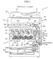
- FIG. 1 is a sectional view showing the internal structure of an image forming apparatus 1 according to one embodiment of the present disclosure.
- a complex machine provided with a printer function and a copier function is illustrated as the image forming apparatus 1 here, the image forming apparatus may be a printer, a copier or a facsimile machine.
- the image forming apparatus 1 includes an apparatus main body 10 having a substantially rectangular parallelepipedic case structure, an auto document feeder 20 arranged atop the apparatus main body 10 and a manual feed tray 46 attached to a lower part of a right side surface 10R of the apparatus main body 10.
- a reading unit 25 for optically reading a document image to be copied
- an image forming station 30 for forming a toner image on a sheet
- a fixing unit 60 for fixing the toner image to the sheet
- a sheet feeding unit 40 for storing standard size sheets to be conveyed to the image forming station 30, a conveyance route 50 in which a standard size sheet is conveyed from the sheet feeding unit 40 or the manual feed tray 46 to a sheet discharge opening 10E via the image forming station 30 and the fixing unit 60
- a conveying unit 55 internally including a sheet conveyance path forming a part of this conveyance route 50.
- the auto document feeder (ADF) 20 is rotatably mounted on the upper surface of the apparatus main body 10.
- the ADF 20 automatically feeds a document sheet to be copied to a predetermined document reading position (position where a first contact glass 241 is mounted) in the apparatus main body 10.
- a predetermined document reading position position where a first contact glass 241 is mounted
- the ADF 20 is opened upward.
- the ADF 20 includes a document tray 21 on which document sheets are to be placed, a document conveying unit 22 for conveying a document sheet via the automatic document reading position and a document discharge tray 23 to which the read document sheet is to be discharged.
- the reading unit 25 optically reads an image of a document sheet via the first contact glass 241 for reading a document sheet automatically fed from the ADF 20 on the upper surface of the apparatus main body 10 or the second contact glass 242 for reading a manually placed document sheet.
- a scanning mechanism including a light source, a moving carriage, a reflecting mirror and the like and an imaging element are housed in the reading unit 25 (not shown).
- the scanning mechanism irradiates light to a document sheet and guides light reflected by the document sheet to the imaging element.
- the imaging element photoelectrically converts the reflected light into an analog electrical signal.
- the analog electrical signal is input to the image forming station 30 after being converted into a digital electrical signal in an A/D conversion circuit.
- the image forming station 30 performs a process of generating a full-color toner image and transferring it to a sheet and includes an image forming unit 32 with four units 32Y, 32M, 32C and 32Bk arranged in a tandem manner for forming a toner image of each of yellow (Y), magenta (M), cyan (C) and black (Bk), an intermediate transfer unit 33 arranged above and adjacent to the image forming unit 32, and a toner supply unit 34 arranged above the intermediate transfer unit 33.
- Each of the image forming units 32Y, 32M, 32C and 32Bk includes a photoconductive drum 321 (referred to as an image bearing member), and a charger 322, an exposure device 323, a developing device 324, a primary transfer roller 325 and a cleaning device 326 arranged around this photoconductive drum 321.
- the photoconductive drum 321 is rotated about its shaft and an electrostatic latent image and a toner image are formed on the circumferential surface thereof.
- a photoconductive drum made of amorphous silicon (a-Si) material can be used as the photoconductive drum 321.
- the charger 322 uniformly charges the surface of the photoconductive drum 321.
- the exposure device 323 includes optical components such as a laser light source, a mirror and a lens and irradiates the circumferential surface of the photoconductive drum 321 with light based on image data of a document image, thereby forming an electrostatic latent image.
- the developing device 324 supplies a toner to the circumferential surface of the photoconductive drum 321 to develop the electrostatic latent image formed on the photoconductive drum 321.
- the developing device 324 is for a two-component developer and includes screw feeders 85, 86, a magnetic roller 82 and a developing roller 83. This developing device 324 is described in detail later.
- the primary transfer roller 325 forms a nip portion together with the photoconductive drum 321 with an intermediate transfer belt 331 of the intermediate transfer unit 33 sandwiched therebetween and primarily transfers a toner image on the photoconductive drum 321 to the intermediate transfer belt 331.
- the cleaning device 326 includes a cleaning roller and the like and cleans the circumferential surface of the photoconductive drum 321 after the transfer of the toner image.
- the intermediate transfer unit 33 includes the intermediate transfer belt 331, a drive roller 332 and a driven roller 333.
- the intermediate transfer belt 331 is an endless belt mounted between the drive roller 332 and the drive roller 333 and toner images from a plurality of photoconductive drums 321 are transferred in a superimposition manner at the same position on the outer circumferential surface of the intermediate transfer belt 331 (primary transfer).
- a secondary transfer roller 35 is arranged to face the circumferential surface of the drive roller 332.
- a nip portion between the drive roller 332 and the secondary transfer roller 35 serves a secondary transfer portion 35A for transferring a full-color toner image formed by the toner images transferred in a superimposition manner to the intermediate transfer belt 331 to a sheet.
- a secondary transfer bias having a polarity opposite to that of the toner image is applied to either one of the drive roller 332 and the secondary transfer roller 35, whereas the other roller is grounded.
- the toner supply unit 34 includes a yellow toner container 34Y, a magenta toner container 34M, a cyan toner container 34C and a black toner container 34Bk. These toner containers 34Y, 34C, 34M and 34Bk are respectively for storing toners of the respective colors and supply the toners of the respective colors to the developing devices 321 of the image forming units 32Y, 32M, 32C and 32Bk corresponding to the respective YMCBk colors via unillustrated supply paths.
- Each of the toner containers 34Y, 34C, 34M and 34Bk includes a conveying screw 341 for conveying the toner in the container to an unillustrated toner discharge opening. This conveying screw 341 is driven and rotated by a driver (not shown), whereby the toner is supplied into the developing device 324.
- the sheet feeding unit 40 includes sheet cassettes 40A, 40B arranged in two levels for storing sheets S1 out of sheets to which an image forming process can be applied. These sheet cassettes 40A, 40B can be pulled out forward from the front side of the apparatus main body 10.
- the sheet cassette 40A (40B) includes a sheet storing portion 41 for storing a sheet stack formed by stacking the sheets S1 one over another and a lift plate 42 for lifting up the sheet stack for sheet feeding.
- a pickup roller 43 and a roller pair composed of a feed roller 44 and a retard roller 45 are arranged above the right end of the sheet cassette 40A (40B). By driving the pickup roller 43 and the feed roller 44, the uppermost sheet S1 of the sheet stack in the sheet cassette 40A is fed one by one and conveyed into an upstream end of the conveyance route 50.
- the manual feed tray 46 is provided at the right side surface 10R of the apparatus main body 10.
- the manual feed tray 46 is attached to the apparatus main body 10 openably and closably about a lower end part thereof.
- the user opens the manual feed tray 46 as shown and places a sheet thereon in the case of manually feeding.
- the sheet placed on the manual feed tray 46 is conveyed into the conveyance route 50 by driving a pickup roller 461 and a feed roller 462.
- the conveyance route 50 includes a main conveyance path 50A for conveying a sheet from the sheet feeding unit 40 to the exit of the fixing unit 60 via the image forming station 30, a reversing conveyance path 50B for returning a sheet having one side printed to the image forming station 30 in the case of printing both sides of the sheet, a switchback conveyance path 50C for conveying a sheet from a downstream end of the main conveyance path 50A to an upstream end of the reversing conveyance path 50B, and a horizontal conveyance path 50D for horizontally conveying a sheet from the downstream end of the main conveyance path 50A to the sheet discharge opening 10E provided in a left side surface 10L of the apparatus main body 10.
- This horizontal conveyance path 50D is mostly formed by the sheet conveyance path provided in the conveying unit 55.
- the fixing unit 60 is an induction heating type fixing device for applying a fixing process of fixing a toner image to a sheet and includes a heating roller 61, a fixing roller 62, a pressure roller 63, a fixing belt 64 and an induction heating unit 65.
- the pressure roller 63 is pressed into contact with the fixing roller 62 to form a fixing nip portion.
- the heating roller 61 and the fixing belt 64 are induction-heated by the induction heating unit 65 to give that heat to the fixing nip portion.
- a sheet passes through the fixing nip portion, whereby a toner image transferred to the sheet is fixed to the sheet.
- FIG. 2 is a vertical sectional view schematically showing the internal structure of the developing device 324.
- the developing device 324 includes a development housing 80 (referred to as a case) defining the internal space of the developing device 324.
- the development housing 80 includes a lid portion 802 for covering respective rollers housed therein from above and a bottom portion 803 connected to the lid portion 802 and forming a lower surface part of the development housing 80.
- This development housing 80 includes a developer storing portion 81 which is a cavity for storing a developer containing a nonmagnetic toner and a magnetic carrier and can convey the developer while agitating it.
- the magnetic roller 82 (referred to as a developer bearing member) arranged in an upper part of the developer storing portion 81
- the developing roller 83 (referred to as a toner bearing member) arranged to face the magnetic roller 82 at a position obliquely upward from the magnetic roller 82
- a developer restricting blade 84 referred to as a layer thickness restricting member
- the developer storing portion 81 includes two adjacent developer storage chambers 81a, 81b extending in a longitudinal direction of the developing device 324. Although the developer storage chambers 81a, 81b are partitioned from each other by a partition plate 801 integrally formed to the bottom portion 803 of the development housing 80 and extending in the longitudinal direction, they communicate with each other via communication paths 804, 805 at both ends in the longitudinal direction (see FIG. 3 ).
- the screw feeders 85, 86 (referred to as an agitating member) are respectively housed in the developer storage chambers 81a, 81b and agitate and convey the developer by rotating about their shafts.
- the screw feeder 86 is arranged to face the magnetic roller 82 in the development housing 80, includes a shaft center 862 and a screw forming portion arranged around the shaft center 862, and agitates and conveys the developer while rotating.
- An outer rim 861 of the screw forming portion has a spiral shape arranged around the shaft center 862.
- the screw feeders 85, 86 are driven and rotated by an unillustrated driving mechanism and developer conveying directions thereof are set to be opposite to each other along an axial direction. This causes the developer to be conveyed in a circulating manner while being agitated between the developer storage chambers 81a, 81b as shown by arrows D1, D2 in FIG. 3 . By this agitation, the toner and the carrier are mixed, whereby the toner is, for example, negatively charged.
- the magnetic roller 82 is arranged along the longitudinal direction of the developing device 324 and rotatable in a counterclockwise direction in FIG. 2 .
- a fixed so-called magnet roll is arranged in the magnetic roller 82.
- the magnet roll has a plurality of magnetic poles and, in this embodiment, includes a pumping pole 821, a restricting pole 822, a main pole 823 and further a conveying pole 824 and a separating pole 825.
- the pumping pole 821 is facing the developer storing portion 81
- the restricting pole 822 is facing the developer restricting blade 84
- the main pole 823 is facing the developing roller 83.
- the conveying pole 824 is arranged between the restricting pole 822 and the main pole 823 and the separating pole 825 is arranged downstream of the main pole 823 in the rotating direction of the magnetic roller 82.
- the magnetic roller 82 magnetically pumps up (receives) the developer from the developer storage chamber 81b onto a circumferential surface 82A thereof by a magnetic force of the pumping pole 821 as shown by an arrow F1 of FIG. 2 .
- the pumped-up developer is magnetically held as a developer layer (magnetic brush layer) on the circumferential surface 82A of the magnetic roller 82 and conveyed toward the developer restricting blade 84 according to the rotation of the magnetic roller 82.
- the developer restricting blade 84 is arranged upstream of the developing roller 83 in the rotating direction of the magnetic roller 82 and restricts the layer thickness of the developer layer magnetically adhering to the circumferential surface 82A of the magnetic roller 82.
- the developer restricting blade 84 is a plate member made of a magnetic material and extending along the longitudinal direction of the magnetic roller 82 and is supported by a predetermined supporting member 841 fixed at an appropriate position of the development housing 80.
- the supporting member 841 is in the shape of a rectangular column having a substantially trapezoidal cross-sectional shape and extending in a rotation axis direction of the magnetic roller 82.
- the supporting member 841 has a facing surface 843 which is one surface extending in its longitudinal direction, intersecting with the developer restricting blade 84 and facing the magnetic roller 82. Further, the developer restricting blade 84 has a restricting surface 842 (i.e. leading end surface of the developer restricting blade 84) which forms a restriction gap of a predetermined dimension between itself and the circumferential surface 82A of the magnetic roller 82.
- a restricting plate 90 arranged to face the rotational circumferential surface of the magnetic roller 82 while being spaced apart by a predetermined distance is arranged upstream of the developer restricting blade 84 in the rotating direction of the magnetic roller 82.
- the restricting plate 90 is a plate-like member made of a resin material and adhesively fixed to the facing surface 843 of the supporting member 841, and the upper end edge thereof is in contact with the developer restricting blade 84.
- the restricting plate 90 has a length extending over the entire length of the magnetic roller 82 in the rotation axis direction.
- a plurality of elongated projections 901 (referred to as projection members) extending at a predetermined angle toward the developer restricting blade 84 are arranged on a surface of the restricting plate 90 facing the magnetic roller 82 ( FIGS. 4A, 4B ).
- the plurality of elongated projections 901 are arranged adjacent to each other along the rotation axis direction of the magnetic roller 82, and groove portions 902 of a predetermined width are formed between adjacent elongated projections.
- the developer layer adhering to the circumferential surface 82A of the magnetic roller 82 by the pumping pole 821 is conveyed toward the developer restricting blade 84 while being held in contact with the restricting plate 90. Note that behaviors of the developer in the restricting plate 90 are described in detail later.
- the developer restricting blade 84 made of the magnetic material is magnetized by the restricting pole 822 of the magnetic roller 82. This causes a magnetic path to be formed between the restricting surface 842 of the developer restricting blade 84 and the restricting pole 822, i.e. in the restriction gap.
- the layer thickness of the developer layer is restricted in the restriction gap. This causes a uniform developer layer having a predetermined thickness to be formed on the circumferential surface 82A.
- the developing roller 83 is arranged to extend along the longitudinal direction of the developing device 324 and in parallel to the magnetic roller 82 and is rotatable in a counterclockwise direction in FIG. 2 .
- the developing roller 83 has a circumferential surface 83A which receives the toner from the developer layer and carries a toner layer while rotating in contact with the developer layer held on the circumferential surface 82A of the magnetic roller 82.
- a facing main pole 831 is arranged at a position facing the main pole 823 of the magnetic roller 82.
- the toner moves from the developer layer on the circumferential surface 82A to the circumferential surface 83A since a magnetic field is formed between the main pole 823 and the facing main pole 831 and a predetermined voltage is set between the circumferential surface 82A and the circumferential surface 83A (developing portion).
- the toner on the circumferential surface 83A is supplied to the circumferential surface of the photoconductive drum 321.
- the developer on the magnetic roller 82 having passed through a facing portion facing the developing roller 83 is separated from the circumferential surface 82A by the separating pole 825, falls down to the developer storage chamber 81b located below in which the screw feeder 86 is housed, and is agitated again.
- the developing roller 83 and the magnetic roller 82 are driven and rotated by a drive source (not shown).
- a clearance of a predetermined dimension is formed between the circumferential surface 83A of the developing roller 83 and the circumferential surface 82A of the magnetic roller 82.
- the clearance is, for example, set at about 130 ⁇ m.
- the developing roller 83 is arranged to face the photoconductive drum 321 through an opening formed in the development housing 80, and a clearance of a predetermined dimension is also formed between the circumferential surface 83A and the circumferential surface of the photoconductive drum 321.
- FIG. 3 is a view showing the internal structure of the developing device 324 over the entire length in the longitudinal direction of the magnetic roller 82 from above.
- FIG. 3 shows a state where the lid portion 802 of the development housing 80 shown in FIG. 2 is removed and the screw feeder 86 is seen between the magnetic roller 82 and the screw feeder 85. Note that the developing roller 83 is not shown in FIG. 3 .
- the screw feeders 85, 86 substantially horizontally adjacent to each other convey the developer in opposite directions along the rotation axis direction of the magnetic roller 82 (arrows D1, D2 of FIG. 3 ). Further, developer conveying paths at ends of these screw feeders 85, 86 in the axial direction are allowed to communicate by the communication paths 804, 805 provided in the bottom portion 803 of the development housing 80, whereby a clockwise developer circulation path is formed as a whole.
- the magnetic roller 82 is arranged to face the screw feeder 86 from above (first facing portion).
- the magnetic roller 82 rotates in a direction R1 in FIGS. 2 and 3 and the screw feeder 86 rotates in an opposite direction (direction R2) to the magnetic roller 82 in the first facing portion.
- a part of the developer from the screw feeder 86 is supplied to the circumferential surface 82A of the magnetic roller 82 (arrow F1 of FIG. 2 ) and the remaining developer is conveyed and agitated in the axial direction (arrow D1 of FIG. 3 ).
- the developer separated from the circumferential surface 82A by the separating pole 825 ( FIG. 2 ) of the magnetic roller 82 flows into the conveyance path of the screw feeder 86 again (arrow F2 of FIG. 2 ).
- the above developer separated from the magnetic roller 82 and flowing to the screw feeder 86 again has a reduced ratio (T/C) of the toner to the carrier constituting the two-component developer. Accordingly, the developer separated from the magnetic roller 82 and the developer agitated and conveyed in the direction of the arrow D1 in the screw feeder 86 have different toner/carrier ratios (T/C).
- the above re-adhering phenomenon of the separated developer to the magnetic roller 82 is attributable to the screw feeder 86.
- Parts where the re-adherence of the separated developer is notable are cyclically distributed on the magnetic roller 82 in conformity with the shape (spiral shape) of the screw outer rim 861 of the screw feeder 86.
- the cyclic distribution approximates to a line formed by projecting a trace of the screw outer rim 861 when the screw feeder 86 rotates on the facing surface (circumferential surface of the magnetic roller 82).
- the toner density is non-uniformly distributed on the magnetic roller 82.
- dotted line parts P shown on the circumferential surface of the magnetic roller 82 represent a distribution of the re-adherence of the separated developer on the underside of the magnetic roller 82 (side facing the screw feeder 86), and the cycle and distribution shape thereof correspond to the shape of the screw outer rim 861 (spiral shape) of the facing screw feeder 86. That is, since the re-adherence of the separated developer is notable at positions of the circumferential surface 82A of the magnetic roller 82 facing the screw outer rim 861, the developer having a low T/C (toner density) is adhering.
- a distribution of the re-adhering developer corresponds to the projected shape of the trace of the screw outer rim 861 on the screw feeder 86 when the magnetic roller 82 and the screw feeder 86 rotate relative to each other on the circumferential surface of the magnetic roller 82.
- solid line parts P' in FIG. 3 show a distribution when this re-adhering developer is conveyed toward the upper side of the circumferential surface 82A of the magnetic roller 82 according to the rotation of the magnetic roller 82.
- the developers having different T/C may have different fluidities. Accordingly, the above re-adhering developer distributed on the magnetic roller 82 and the surrounding developer supplied from below the screw feeder 86 may cause unevenness in the amount of the developer adhering to the circumferential surface 82A of the magnetic roller 82 (height difference of the developer layer on the circumferential surface 82A).
- the restricting plate 90 is arranged at a position below the magnetic roller 82 and facing the outer circumferential surface of the magnetic roller 82 to solve the problem of the re-adherence of the separated developer (re-adhering developer). Note that, in FIG. 3 , the restricting plate 90 is shown to be displaced upward for the explanation of an inclined relationship to be described later. In an actual positional relationship, the restricting plate 90 is located below and upstream of the developer restricting blade 84 in the rotating direction of the magnetic roller 82 as shown in FIG. 2 .
- FIG. 4A is an enlarged view of the restricting plate 90 according to this embodiment showing the surface facing the circumferential surface 82A of the magnetic roller 82.
- the restricting plate 90 is formed of a plate-like resin member having a predetermined thickness, and the elongated projections 901 (referred to as projection members) convexly projecting from a base portion 903 and the groove portions 902 in the form of recesses (grooves) arranged between the elongated projections 901 are arranged on the surface facing the magnetic roller 82 as shown in FIG. 4B (sectional view along A-A' of FIG. 4A ).
- These elongated projections 901 are inclined at a predetermined angle to a line perpendicular to an axis of rotation of the magnetic roller 82 (line perpendicular to A-A' line of FIG. 4A ) in such a direction that the upper ends are located more toward the right end of the restricting plate 90 (referred to as a first direction).
- the restricting plate 90 is so arranged that a plurality of elongated projections 901 facing the circumferential surface 82A of the magnetic roller 82 and adjacent to each other come into contact with the developer layer on the magnetic roller 82.
- a direction in which the elongated projections 901 are inclined is set to be opposite to the inclination (dotted line parts P) of the distribution of the re-adhering developer on the circumferential surface of the magnetic roller 82.
- the projected shape of the screw outer rim 861 of the screw feeder 86 on the circumferential surface of the magnetic roller 82 when the magnetic roller 82 and the screw feeder 86 rotate relative to each other is inclined toward one end 828 of the rotary shaft of the magnetic roller 82 along the rotation axis direction of the magnetic roller 82.
- the projected shape of the inclined elongated projections 901 on the circumferential surface of the magnetic roller 82 is inclined toward another end 829 of the rotary shaft of the magnetic roller 82.
- the re-adhering developer cyclically distributed on the magnetic roller 82 is agitated together with the surrounding developer and moves in a direction (direction intersecting with the dotted line parts P) away from areas (dotted line parts P of FIG. 3 ) where it has been distributed by being held in contact with the elongated projections 901.
- the developers having different toner densities and eccentrically located on the magnetic roller 82 are mixed to make the toner density uniform.
- an interval between the adjacent elongated projections 901 is set to be smaller than an interval between adjacent sections of the screw outer rim 861 of the screw feeder 86 to be projected on the magnetic roller 82.
- the plurality of elongated projections 901 successively come into contact with the developer area (dotted line part P of FIG. 3 ) corresponding to the section of the screw outer rim 861 at one position on the magnetic roller 82, wherefore the movement of the developer in finer areas and the uniformity of the toner density are realized.
- the magnetic roller 82 and the screw feeder 86 rotate in opposite directions in their facing portions, the direction of the inclination of the elongated projections 901 with respect to the rotation axis direction of the magnetic roller 82 is the same as the conveying direction D1 of the developer with respect to rotation axis direction of the screw feeder 86. That is, both are set to extend toward the other end 829 of the rotary shaft of the magnetic roller 82.
- the magnetic roller 82 and the screw feeder 86 rotate in the opposite directions in their facing portions, and the developer on the magnetic roller 82 having a variation of the toner density in conformity with the shape of the screw outer rim 861 of the screw feeder 86 can be moved in the same direction as the direction in which the developer is conveyed by the screw outer rim 861 with respect to the rotation axis direction of the screw feeder 86.
- the developer on the magnetic roller 82 can be agitated and a variation of the toner density can be more suppressed.
- the restricting plate 90 of this embodiment it is possible to reduce the cyclic distribution (toner density distribution) of the re-adhering developer caused by the re-adherence of the developer having passed through the main pole 823 of the magnetic roller 82 to the magnetic roller 82 due to the rotational force of the screw feeder 86 after being separated from the magnetic roller 82 when the amount of the developer in the developing device 324 is large (e.g. 400 g). Further, an image defect caused by this cyclical distribution of the re-adhering developer can be effectively suppressed.
- the image forming apparatus 1 includes the photoconductive drum 321 on the surface of which an electrostatic latent image is to be formed, and the developing device 324 described above.
- An electrostatic latent image on the photoconductive drum 321 is visualized by the toner supplied from the developing device 324. According to this configuration, when the amount of the developer in the developing device 324 is large, it is possible to suppress a variation of the toner density on the magnetic roller 82 in conformity with the screw shape of the screw feeder 86 and reduce the unevenness of image density on the photoconductive drum 321 caused by such a variation.
- the present disclosure is not limited to this and, for example, the following modifications may be adopted.
- FIGS. 5A and 5B are views showing a restricting plate 91 according to a second embodiment of the present disclosure.
- a base portion 913 is formed with a plurality of first grooves 911 (referred to as first groove portions) inclined such that the upper ends thereof are shifted to the right (referred to as a second direction) and a plurality of second grooves 912 (referred to as second groove portions) inclined such that the upper ends thereof are shifted to the left (referred to as a third direction), the first and second grooves 911, 912 extending in directions intersecting with each other.
- Rhombic projection portions 914 are formed between the first grooves 911 and the second grooves 912.
- an interval between the first grooves 911 or the second grooves 912 is preferably set to be smaller than an interval (pitch) between the sections of the screw outer rim 861 of the screw feeder 86 projected on the magnetic roller 82. In this case, the movement of the developer is realized in finer areas and the unevenness (height difference) of the amount of the developer on the magnetic roller 82 can be made more uniform. Note that since the other configurations and arrangement relationships are the same as in the first embodiment, detailed description is not made.
- Table 1 shows an evaluation result of screw unevenness obtained by visually evaluating unevenness appearing due to the screw shape of the screw feeder 86 (screw unevenness) in forming a high-density image on the entire surface of an A3 print.
- o indicates no appearance of screw unevenness
- ⁇ indicates partial unevenness appearing on end parts of the magnetic roller 82 in the axial direction since the amount of the developer slightly varies among the groove portions of the restricting plate 90 when the amount of the developer on the magnetic roller 82 is small, and ⁇ indicates notable appearance of screw unevenness. In any one of these, whether or not unevenness appeared was evaluated while the amount of the developer in the developing device 324 is changed.
- Table 1 Amount of Developer (g)
- Example 1 Comparative Example 1 Comparative Example 2 300 ⁇ O ⁇ O 325 O O O O O 350 O O O O O 375 O O ⁇ ⁇ 400 O O ⁇ ⁇
Landscapes
- Physics & Mathematics (AREA)
- General Physics & Mathematics (AREA)
- Dry Development In Electrophotography (AREA)
Applications Claiming Priority (1)
| Application Number | Priority Date | Filing Date | Title |
|---|---|---|---|
| JP2011202075A JP5597610B2 (ja) | 2011-09-15 | 2011-09-15 | 現像装置、およびそれを備えた画像形成装置 |
Publications (3)
| Publication Number | Publication Date |
|---|---|
| EP2570856A2 true EP2570856A2 (de) | 2013-03-20 |
| EP2570856A3 EP2570856A3 (de) | 2013-06-12 |
| EP2570856B1 EP2570856B1 (de) | 2019-03-06 |
Family
ID=47115121
Family Applications (1)
| Application Number | Title | Priority Date | Filing Date |
|---|---|---|---|
| EP12006322.7A Not-in-force EP2570856B1 (de) | 2011-09-15 | 2012-09-07 | Entwicklervorrichtung und damit versehene Bilderzeugungsvorrichtung |
Country Status (4)
| Country | Link |
|---|---|
| US (1) | US8831486B2 (de) |
| EP (1) | EP2570856B1 (de) |
| JP (1) | JP5597610B2 (de) |
| CN (1) | CN102998945B (de) |
Families Citing this family (6)
| Publication number | Priority date | Publication date | Assignee | Title |
|---|---|---|---|---|
| JP5597611B2 (ja) * | 2011-09-15 | 2014-10-01 | 京セラドキュメントソリューションズ株式会社 | 現像装置、およびそれを備えた画像形成装置 |
| JP6543993B2 (ja) * | 2014-09-09 | 2019-07-17 | 富士ゼロックス株式会社 | 現像装置、可視像形成装置および画像形成装置 |
| JP2016142968A (ja) * | 2015-02-04 | 2016-08-08 | 京セラドキュメントソリューションズ株式会社 | 画像形成装置 |
| JP6641986B2 (ja) * | 2015-12-25 | 2020-02-05 | コニカミノルタ株式会社 | 現像装置および画像形成装置 |
| JP6468221B2 (ja) * | 2016-03-02 | 2019-02-13 | 京セラドキュメントソリューションズ株式会社 | 現像装置、画像形成装置 |
| JP6468220B2 (ja) * | 2016-03-02 | 2019-02-13 | 京セラドキュメントソリューションズ株式会社 | 現像装置、画像形成装置 |
Citations (1)
| Publication number | Priority date | Publication date | Assignee | Title |
|---|---|---|---|---|
| JP2011202075A (ja) | 2010-03-26 | 2011-10-13 | Sumitomo Bakelite Co Ltd | フェノール樹脂成形材料 |
Family Cites Families (11)
| Publication number | Priority date | Publication date | Assignee | Title |
|---|---|---|---|---|
| JPS60184067U (ja) * | 1984-05-16 | 1985-12-06 | 京セラミタ株式会社 | 現像装置 |
| JP3126567B2 (ja) * | 1993-10-19 | 2001-01-22 | 富士通株式会社 | 現像装置 |
| JP4070387B2 (ja) * | 1999-06-21 | 2008-04-02 | 株式会社リコー | 現像装置及び画像形成装置 |
| JP4058206B2 (ja) * | 1999-10-15 | 2008-03-05 | 株式会社リコー | 現像装置及び画像形成装置 |
| JP4092072B2 (ja) * | 2000-12-08 | 2008-05-28 | 株式会社リコー | 画像形成装置 |
| JP2007322707A (ja) | 2006-05-31 | 2007-12-13 | Kyocera Mita Corp | 現像装置 |
| JP2008299014A (ja) * | 2007-05-30 | 2008-12-11 | Seiko Epson Corp | 画像形成装置、及び、画像形成システム |
| JP4862748B2 (ja) * | 2007-05-30 | 2012-01-25 | セイコーエプソン株式会社 | 現像装置、画像形成装置、及び、画像形成システム |
| JP2009193064A (ja) * | 2008-01-18 | 2009-08-27 | Kyocera Mita Corp | 現像装置及び画像形成装置 |
| JP2009198671A (ja) * | 2008-02-20 | 2009-09-03 | Seiko Epson Corp | 現像ローラ、現像装置および画像形成装置 |
| JP5407451B2 (ja) * | 2009-03-17 | 2014-02-05 | 株式会社リコー | 現像装置及びプロセスカートリッジ、画像形成装置 |
-
2011
- 2011-09-15 JP JP2011202075A patent/JP5597610B2/ja not_active Expired - Fee Related
-
2012
- 2012-09-07 EP EP12006322.7A patent/EP2570856B1/de not_active Not-in-force
- 2012-09-10 CN CN201210333645.8A patent/CN102998945B/zh not_active Expired - Fee Related
- 2012-09-11 US US13/609,370 patent/US8831486B2/en not_active Expired - Fee Related
Patent Citations (1)
| Publication number | Priority date | Publication date | Assignee | Title |
|---|---|---|---|---|
| JP2011202075A (ja) | 2010-03-26 | 2011-10-13 | Sumitomo Bakelite Co Ltd | フェノール樹脂成形材料 |
Also Published As
| Publication number | Publication date |
|---|---|
| CN102998945A (zh) | 2013-03-27 |
| CN102998945B (zh) | 2015-03-11 |
| US20130071145A1 (en) | 2013-03-21 |
| JP2013064781A (ja) | 2013-04-11 |
| EP2570856A3 (de) | 2013-06-12 |
| US8831486B2 (en) | 2014-09-09 |
| EP2570856B1 (de) | 2019-03-06 |
| JP5597610B2 (ja) | 2014-10-01 |
Similar Documents
| Publication | Publication Date | Title |
|---|---|---|
| US8135311B2 (en) | Developing unit having effective developer transportability, and process cartridge and image forming apparatus using the same | |
| CN100562810C (zh) | 显影装置及具有该显影装置的图像形成装置 | |
| US9176457B2 (en) | Image forming apparatus and waste toner conveying device incorporated in same | |
| EP1998231A1 (de) | Entwicklungsvorrichtung und Bilderzeugungsvorrichtung damit | |
| CN101794102B (zh) | 显影装置以及使用该显影装置的图像形成设备 | |
| EP2570856B1 (de) | Entwicklervorrichtung und damit versehene Bilderzeugungsvorrichtung | |
| CN101794100A (zh) | 显影装置以及使用该显影装置的图像形成装置 | |
| US8948658B2 (en) | Developing device and image forming apparatus | |
| US8682226B2 (en) | Development device and image forming apparatus provided therewith | |
| JP5439409B2 (ja) | 現像装置及びそれを備えた画像形成装置 | |
| EP2570857B1 (de) | Entwicklervorrichtung und damit versehene Bilderzeugungsvorrichtung | |
| US8843035B2 (en) | Developing device and image forming apparatus provided with same | |
| US10261444B2 (en) | Developing apparatus | |
| US10895827B2 (en) | Developer conveyor having three blades | |
| JP2010113030A (ja) | 画像形成装置 | |
| JP5481319B2 (ja) | 現像装置及びそれを備えた画像形成装置 | |
| US8660466B2 (en) | Development device and image forming apparatus including the same | |
| JP7031197B2 (ja) | 画像形成装置 | |
| US20110170910A1 (en) | Developing device and image forming apparatus including the same | |
| JP7003603B2 (ja) | 画像形成装置 | |
| JP7031196B2 (ja) | 画像形成装置 | |
| JP5879236B2 (ja) | 現像装置、およびこれを備えた画像形成装置 | |
| JP2014191233A (ja) | 現像装置、像担持体ユニットおよび画像形成装置 | |
| JP2008122764A (ja) | 補給トナーの混合撹拌方法、現像装置、および、画像形成装置 | |
| JP2017207599A (ja) | 現像装置、およびこれを備えた画像形成装置 |
Legal Events
| Date | Code | Title | Description |
|---|---|---|---|
| PUAI | Public reference made under article 153(3) epc to a published international application that has entered the european phase |
Free format text: ORIGINAL CODE: 0009012 |
|
| AK | Designated contracting states |
Kind code of ref document: A2 Designated state(s): AL AT BE BG CH CY CZ DE DK EE ES FI FR GB GR HR HU IE IS IT LI LT LU LV MC MK MT NL NO PL PT RO RS SE SI SK SM TR |
|
| AX | Request for extension of the european patent |
Extension state: BA ME |
|
| PUAL | Search report despatched |
Free format text: ORIGINAL CODE: 0009013 |
|
| AK | Designated contracting states |
Kind code of ref document: A3 Designated state(s): AL AT BE BG CH CY CZ DE DK EE ES FI FR GB GR HR HU IE IS IT LI LT LU LV MC MK MT NL NO PL PT RO RS SE SI SK SM TR |
|
| AX | Request for extension of the european patent |
Extension state: BA ME |
|
| RIC1 | Information provided on ipc code assigned before grant |
Ipc: G03G 15/09 20060101ALI20130506BHEP Ipc: G03G 15/08 20060101AFI20130506BHEP |
|
| 17P | Request for examination filed |
Effective date: 20131205 |
|
| RBV | Designated contracting states (corrected) |
Designated state(s): AL AT BE BG CH CY CZ DE DK EE ES FI FR GB GR HR HU IE IS IT LI LT LU LV MC MK MT NL NO PL PT RO RS SE SI SK SM TR |
|
| 17Q | First examination report despatched |
Effective date: 20160114 |
|
| GRAP | Despatch of communication of intention to grant a patent |
Free format text: ORIGINAL CODE: EPIDOSNIGR1 |
|
| STAA | Information on the status of an ep patent application or granted ep patent |
Free format text: STATUS: GRANT OF PATENT IS INTENDED |
|
| INTG | Intention to grant announced |
Effective date: 20181024 |
|
| GRAS | Grant fee paid |
Free format text: ORIGINAL CODE: EPIDOSNIGR3 |
|
| GRAA | (expected) grant |
Free format text: ORIGINAL CODE: 0009210 |
|
| STAA | Information on the status of an ep patent application or granted ep patent |
Free format text: STATUS: THE PATENT HAS BEEN GRANTED |
|
| AK | Designated contracting states |
Kind code of ref document: B1 Designated state(s): AL AT BE BG CH CY CZ DE DK EE ES FI FR GB GR HR HU IE IS IT LI LT LU LV MC MK MT NL NO PL PT RO RS SE SI SK SM TR |
|
| REG | Reference to a national code |
Ref country code: GB Ref legal event code: FG4D |
|
| REG | Reference to a national code |
Ref country code: CH Ref legal event code: EP Ref country code: AT Ref legal event code: REF Ref document number: 1105347 Country of ref document: AT Kind code of ref document: T Effective date: 20190315 |
|
| REG | Reference to a national code |
Ref country code: DE Ref legal event code: R096 Ref document number: 602012057344 Country of ref document: DE |
|
| REG | Reference to a national code |
Ref country code: IE Ref legal event code: FG4D |
|
| REG | Reference to a national code |
Ref country code: NL Ref legal event code: MP Effective date: 20190306 |
|
| REG | Reference to a national code |
Ref country code: LT Ref legal event code: MG4D |
|
| PG25 | Lapsed in a contracting state [announced via postgrant information from national office to epo] |
Ref country code: LT Free format text: LAPSE BECAUSE OF FAILURE TO SUBMIT A TRANSLATION OF THE DESCRIPTION OR TO PAY THE FEE WITHIN THE PRESCRIBED TIME-LIMIT Effective date: 20190306 Ref country code: FI Free format text: LAPSE BECAUSE OF FAILURE TO SUBMIT A TRANSLATION OF THE DESCRIPTION OR TO PAY THE FEE WITHIN THE PRESCRIBED TIME-LIMIT Effective date: 20190306 Ref country code: NO Free format text: LAPSE BECAUSE OF FAILURE TO SUBMIT A TRANSLATION OF THE DESCRIPTION OR TO PAY THE FEE WITHIN THE PRESCRIBED TIME-LIMIT Effective date: 20190606 Ref country code: SE Free format text: LAPSE BECAUSE OF FAILURE TO SUBMIT A TRANSLATION OF THE DESCRIPTION OR TO PAY THE FEE WITHIN THE PRESCRIBED TIME-LIMIT Effective date: 20190306 |
|
| PG25 | Lapsed in a contracting state [announced via postgrant information from national office to epo] |
Ref country code: LV Free format text: LAPSE BECAUSE OF FAILURE TO SUBMIT A TRANSLATION OF THE DESCRIPTION OR TO PAY THE FEE WITHIN THE PRESCRIBED TIME-LIMIT Effective date: 20190306 Ref country code: NL Free format text: LAPSE BECAUSE OF FAILURE TO SUBMIT A TRANSLATION OF THE DESCRIPTION OR TO PAY THE FEE WITHIN THE PRESCRIBED TIME-LIMIT Effective date: 20190306 Ref country code: HR Free format text: LAPSE BECAUSE OF FAILURE TO SUBMIT A TRANSLATION OF THE DESCRIPTION OR TO PAY THE FEE WITHIN THE PRESCRIBED TIME-LIMIT Effective date: 20190306 Ref country code: GR Free format text: LAPSE BECAUSE OF FAILURE TO SUBMIT A TRANSLATION OF THE DESCRIPTION OR TO PAY THE FEE WITHIN THE PRESCRIBED TIME-LIMIT Effective date: 20190607 Ref country code: RS Free format text: LAPSE BECAUSE OF FAILURE TO SUBMIT A TRANSLATION OF THE DESCRIPTION OR TO PAY THE FEE WITHIN THE PRESCRIBED TIME-LIMIT Effective date: 20190306 Ref country code: BG Free format text: LAPSE BECAUSE OF FAILURE TO SUBMIT A TRANSLATION OF THE DESCRIPTION OR TO PAY THE FEE WITHIN THE PRESCRIBED TIME-LIMIT Effective date: 20190606 |
|
| REG | Reference to a national code |
Ref country code: AT Ref legal event code: MK05 Ref document number: 1105347 Country of ref document: AT Kind code of ref document: T Effective date: 20190306 |
|
| PG25 | Lapsed in a contracting state [announced via postgrant information from national office to epo] |
Ref country code: ES Free format text: LAPSE BECAUSE OF FAILURE TO SUBMIT A TRANSLATION OF THE DESCRIPTION OR TO PAY THE FEE WITHIN THE PRESCRIBED TIME-LIMIT Effective date: 20190306 Ref country code: EE Free format text: LAPSE BECAUSE OF FAILURE TO SUBMIT A TRANSLATION OF THE DESCRIPTION OR TO PAY THE FEE WITHIN THE PRESCRIBED TIME-LIMIT Effective date: 20190306 Ref country code: CZ Free format text: LAPSE BECAUSE OF FAILURE TO SUBMIT A TRANSLATION OF THE DESCRIPTION OR TO PAY THE FEE WITHIN THE PRESCRIBED TIME-LIMIT Effective date: 20190306 Ref country code: RO Free format text: LAPSE BECAUSE OF FAILURE TO SUBMIT A TRANSLATION OF THE DESCRIPTION OR TO PAY THE FEE WITHIN THE PRESCRIBED TIME-LIMIT Effective date: 20190306 Ref country code: SK Free format text: LAPSE BECAUSE OF FAILURE TO SUBMIT A TRANSLATION OF THE DESCRIPTION OR TO PAY THE FEE WITHIN THE PRESCRIBED TIME-LIMIT Effective date: 20190306 Ref country code: IT Free format text: LAPSE BECAUSE OF FAILURE TO SUBMIT A TRANSLATION OF THE DESCRIPTION OR TO PAY THE FEE WITHIN THE PRESCRIBED TIME-LIMIT Effective date: 20190306 Ref country code: AL Free format text: LAPSE BECAUSE OF FAILURE TO SUBMIT A TRANSLATION OF THE DESCRIPTION OR TO PAY THE FEE WITHIN THE PRESCRIBED TIME-LIMIT Effective date: 20190306 Ref country code: PT Free format text: LAPSE BECAUSE OF FAILURE TO SUBMIT A TRANSLATION OF THE DESCRIPTION OR TO PAY THE FEE WITHIN THE PRESCRIBED TIME-LIMIT Effective date: 20190706 |
|
| PG25 | Lapsed in a contracting state [announced via postgrant information from national office to epo] |
Ref country code: SM Free format text: LAPSE BECAUSE OF FAILURE TO SUBMIT A TRANSLATION OF THE DESCRIPTION OR TO PAY THE FEE WITHIN THE PRESCRIBED TIME-LIMIT Effective date: 20190306 Ref country code: PL Free format text: LAPSE BECAUSE OF FAILURE TO SUBMIT A TRANSLATION OF THE DESCRIPTION OR TO PAY THE FEE WITHIN THE PRESCRIBED TIME-LIMIT Effective date: 20190306 |
|
| REG | Reference to a national code |
Ref country code: DE Ref legal event code: R097 Ref document number: 602012057344 Country of ref document: DE |
|
| PG25 | Lapsed in a contracting state [announced via postgrant information from national office to epo] |
Ref country code: AT Free format text: LAPSE BECAUSE OF FAILURE TO SUBMIT A TRANSLATION OF THE DESCRIPTION OR TO PAY THE FEE WITHIN THE PRESCRIBED TIME-LIMIT Effective date: 20190306 Ref country code: IS Free format text: LAPSE BECAUSE OF FAILURE TO SUBMIT A TRANSLATION OF THE DESCRIPTION OR TO PAY THE FEE WITHIN THE PRESCRIBED TIME-LIMIT Effective date: 20190706 |
|
| PLBE | No opposition filed within time limit |
Free format text: ORIGINAL CODE: 0009261 |
|
| STAA | Information on the status of an ep patent application or granted ep patent |
Free format text: STATUS: NO OPPOSITION FILED WITHIN TIME LIMIT |
|
| PG25 | Lapsed in a contracting state [announced via postgrant information from national office to epo] |
Ref country code: DK Free format text: LAPSE BECAUSE OF FAILURE TO SUBMIT A TRANSLATION OF THE DESCRIPTION OR TO PAY THE FEE WITHIN THE PRESCRIBED TIME-LIMIT Effective date: 20190306 |
|
| 26N | No opposition filed |
Effective date: 20191209 |
|
| PG25 | Lapsed in a contracting state [announced via postgrant information from national office to epo] |
Ref country code: SI Free format text: LAPSE BECAUSE OF FAILURE TO SUBMIT A TRANSLATION OF THE DESCRIPTION OR TO PAY THE FEE WITHIN THE PRESCRIBED TIME-LIMIT Effective date: 20190306 |
|
| PG25 | Lapsed in a contracting state [announced via postgrant information from national office to epo] |
Ref country code: TR Free format text: LAPSE BECAUSE OF FAILURE TO SUBMIT A TRANSLATION OF THE DESCRIPTION OR TO PAY THE FEE WITHIN THE PRESCRIBED TIME-LIMIT Effective date: 20190306 |
|
| PG25 | Lapsed in a contracting state [announced via postgrant information from national office to epo] |
Ref country code: MC Free format text: LAPSE BECAUSE OF FAILURE TO SUBMIT A TRANSLATION OF THE DESCRIPTION OR TO PAY THE FEE WITHIN THE PRESCRIBED TIME-LIMIT Effective date: 20190306 |
|
| REG | Reference to a national code |
Ref country code: CH Ref legal event code: PL |
|
| PG25 | Lapsed in a contracting state [announced via postgrant information from national office to epo] |
Ref country code: CH Free format text: LAPSE BECAUSE OF NON-PAYMENT OF DUE FEES Effective date: 20190930 Ref country code: LU Free format text: LAPSE BECAUSE OF NON-PAYMENT OF DUE FEES Effective date: 20190907 Ref country code: LI Free format text: LAPSE BECAUSE OF NON-PAYMENT OF DUE FEES Effective date: 20190930 Ref country code: IE Free format text: LAPSE BECAUSE OF NON-PAYMENT OF DUE FEES Effective date: 20190907 |
|
| REG | Reference to a national code |
Ref country code: BE Ref legal event code: MM Effective date: 20190930 |
|
| PG25 | Lapsed in a contracting state [announced via postgrant information from national office to epo] |
Ref country code: BE Free format text: LAPSE BECAUSE OF NON-PAYMENT OF DUE FEES Effective date: 20190930 |
|
| PGFP | Annual fee paid to national office [announced via postgrant information from national office to epo] |
Ref country code: GB Payment date: 20200826 Year of fee payment: 9 Ref country code: FR Payment date: 20200812 Year of fee payment: 9 Ref country code: DE Payment date: 20200826 Year of fee payment: 9 |
|
| PG25 | Lapsed in a contracting state [announced via postgrant information from national office to epo] |
Ref country code: CY Free format text: LAPSE BECAUSE OF FAILURE TO SUBMIT A TRANSLATION OF THE DESCRIPTION OR TO PAY THE FEE WITHIN THE PRESCRIBED TIME-LIMIT Effective date: 20190306 |
|
| PG25 | Lapsed in a contracting state [announced via postgrant information from national office to epo] |
Ref country code: HU Free format text: LAPSE BECAUSE OF FAILURE TO SUBMIT A TRANSLATION OF THE DESCRIPTION OR TO PAY THE FEE WITHIN THE PRESCRIBED TIME-LIMIT; INVALID AB INITIO Effective date: 20120907 Ref country code: MT Free format text: LAPSE BECAUSE OF FAILURE TO SUBMIT A TRANSLATION OF THE DESCRIPTION OR TO PAY THE FEE WITHIN THE PRESCRIBED TIME-LIMIT Effective date: 20190306 |
|
| REG | Reference to a national code |
Ref country code: DE Ref legal event code: R119 Ref document number: 602012057344 Country of ref document: DE |
|
| GBPC | Gb: european patent ceased through non-payment of renewal fee |
Effective date: 20210907 |
|
| PG25 | Lapsed in a contracting state [announced via postgrant information from national office to epo] |
Ref country code: MK Free format text: LAPSE BECAUSE OF FAILURE TO SUBMIT A TRANSLATION OF THE DESCRIPTION OR TO PAY THE FEE WITHIN THE PRESCRIBED TIME-LIMIT Effective date: 20190306 |
|
| PG25 | Lapsed in a contracting state [announced via postgrant information from national office to epo] |
Ref country code: GB Free format text: LAPSE BECAUSE OF NON-PAYMENT OF DUE FEES Effective date: 20210907 Ref country code: FR Free format text: LAPSE BECAUSE OF NON-PAYMENT OF DUE FEES Effective date: 20210930 Ref country code: DE Free format text: LAPSE BECAUSE OF NON-PAYMENT OF DUE FEES Effective date: 20220401 |