EP2571062A2 - Solarmodul - Google Patents
Solarmodul Download PDFInfo
- Publication number
- EP2571062A2 EP2571062A2 EP12181389A EP12181389A EP2571062A2 EP 2571062 A2 EP2571062 A2 EP 2571062A2 EP 12181389 A EP12181389 A EP 12181389A EP 12181389 A EP12181389 A EP 12181389A EP 2571062 A2 EP2571062 A2 EP 2571062A2
- Authority
- EP
- European Patent Office
- Prior art keywords
- solar cell
- substrate
- rib
- cell units
- height
- Prior art date
- Legal status (The legal status is an assumption and is not a legal conclusion. Google has not performed a legal analysis and makes no representation as to the accuracy of the status listed.)
- Withdrawn
Links
- 239000000758 substrate Substances 0.000 claims abstract description 55
- 239000008393 encapsulating agent Substances 0.000 claims description 31
- 239000007787 solid Substances 0.000 claims description 6
- 238000000034 method Methods 0.000 description 11
- 238000003475 lamination Methods 0.000 description 10
- 238000002347 injection Methods 0.000 description 8
- 239000007924 injection Substances 0.000 description 8
- 238000006073 displacement reaction Methods 0.000 description 3
- 238000007373 indentation Methods 0.000 description 3
- 238000010586 diagram Methods 0.000 description 2
- 239000000853 adhesive Substances 0.000 description 1
- 230000001070 adhesive effect Effects 0.000 description 1
- 239000002390 adhesive tape Substances 0.000 description 1
- 230000007547 defect Effects 0.000 description 1
- 230000000694 effects Effects 0.000 description 1
- 230000005611 electricity Effects 0.000 description 1
- 239000011521 glass Substances 0.000 description 1
- 238000004519 manufacturing process Methods 0.000 description 1
- 239000000463 material Substances 0.000 description 1
- 239000005022 packaging material Substances 0.000 description 1
- 238000012858 packaging process Methods 0.000 description 1
- 238000004381 surface treatment Methods 0.000 description 1
- 238000003466 welding Methods 0.000 description 1
Images



Classifications
-
- H—ELECTRICITY
- H10—SEMICONDUCTOR DEVICES; ELECTRIC SOLID-STATE DEVICES NOT OTHERWISE PROVIDED FOR
- H10F—INORGANIC SEMICONDUCTOR DEVICES SENSITIVE TO INFRARED RADIATION, LIGHT, ELECTROMAGNETIC RADIATION OF SHORTER WAVELENGTH OR CORPUSCULAR RADIATION
- H10F77/00—Constructional details of devices covered by this subclass
- H10F77/40—Optical elements or arrangements
- H10F77/42—Optical elements or arrangements directly associated or integrated with photovoltaic cells, e.g. light-reflecting means or light-concentrating means
- H10F77/488—Reflecting light-concentrating means, e.g. parabolic mirrors or concentrators using total internal reflection
-
- H—ELECTRICITY
- H10—SEMICONDUCTOR DEVICES; ELECTRIC SOLID-STATE DEVICES NOT OTHERWISE PROVIDED FOR
- H10F—INORGANIC SEMICONDUCTOR DEVICES SENSITIVE TO INFRARED RADIATION, LIGHT, ELECTROMAGNETIC RADIATION OF SHORTER WAVELENGTH OR CORPUSCULAR RADIATION
- H10F19/00—Integrated devices, or assemblies of multiple devices, comprising at least one photovoltaic cell covered by group H10F10/00, e.g. photovoltaic modules
- H10F19/80—Encapsulations or containers for integrated devices, or assemblies of multiple devices, having photovoltaic cells
- H10F19/85—Protective back sheets
-
- Y—GENERAL TAGGING OF NEW TECHNOLOGICAL DEVELOPMENTS; GENERAL TAGGING OF CROSS-SECTIONAL TECHNOLOGIES SPANNING OVER SEVERAL SECTIONS OF THE IPC; TECHNICAL SUBJECTS COVERED BY FORMER USPC CROSS-REFERENCE ART COLLECTIONS [XRACs] AND DIGESTS
- Y02—TECHNOLOGIES OR APPLICATIONS FOR MITIGATION OR ADAPTATION AGAINST CLIMATE CHANGE
- Y02E—REDUCTION OF GREENHOUSE GAS [GHG] EMISSIONS, RELATED TO ENERGY GENERATION, TRANSMISSION OR DISTRIBUTION
- Y02E10/00—Energy generation through renewable energy sources
- Y02E10/50—Photovoltaic [PV] energy
- Y02E10/52—PV systems with concentrators
Definitions
- the present disclosure relates to a solar module. More particularly, the present disclosure relates to a back sheet of a solar module.
- a solar module includes the main elements of solar cells, a back sheet, and packaging material filled between the solar cells and the back sheet.
- the solar cells are connected to each other by welding strips, and then the solar cells are sealed by the encapsulant after the encapsulant is heated to a specific temperature in a lamination process.
- the encapsulant is heated in a pressurized and vacuum pressure state, the solar cells are easily displaced and contact each other, thereby causing a short-circuit.
- a typical way in which this problem is dealt with involves attaching heat-resistant adhesive tape to the back sides of the solar cells to decrease the amount of displacement of the same.
- a solar module is provided as an aspect of the invention.
- the solar module includes a back sheet, a solar cell unit, and a cover sheet.
- the back sheet includes a substrate, and a rib formed on the substrate.
- the solar cell unit is disposed on the back sheet and next to the rib.
- the solar cell unit includes a bottom surface facing the back sheet and a light-receiving surface disposed opposite to the bottom surface.
- the cover sheet is disposed on the solar cell unit.
- a first height from a top surface of the substrate to an upper end of the rib is greater than a second height from the top surface of the substrate to the bottom surface of the solar cell unit, and the first height is not greater than a third height from the top surface of the substrate to a lower surface of the cover sheet facing the solar cell unit.
- the solar cell units can be aligned by the ribs on the back sheet to maintain a space between the solar cell units and to prevent the solar cell units from undergoing displacement during a lamination process.
- the ribs can reflect incident light to thereby further increase the efficiency of the solar module.
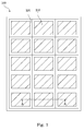
- Fig. 1 is a top view of an embodiment of a solar module of the invention.
- the solar module 100 includes plural solar cell units 110 and a back sheet 120 (see Fig. 2 ).
- the solar cell units 110 are disposed in rows and columns on the back sheet 120.
- the back sheet 120 has plural ribs 124, and the solar cell units 110 are disposed next to the ribs 124. Gaps between the solar cell units 110 are maintained by the ribs 124.
- the ribs 124 may be parallel to each other.
- the ribs 124 are arranged in rows and columns, thereby forming a lattice array.
- the ribs 124 may surround the solar cell units 110.
- the ribs 124 can be contacted with the solar cell units 110 or spatially separated from the solar cell units 110. More particularly, there is a plurality of receiving spaces defined by the ribs 124, and the solar cell units 110 are disposed in the receiving spaces respectively.
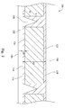
- Fig. 2 is a cross-section of the solar module along a sectional line A-A of Fig. 1 .
- the solar module 100 includes the solar cell units 110, the back sheet 120, a cover sheet 130.
- the solar module 100 may further include an encapsulant 118.
- the solar cell units 110 are disposed between the back sheet 120 and the cover sheet 130.
- Each of the solar cell units 110 includes a light-receiving surface 112 facing upwardly (i.e., the cover sheet 130) to receive light from the sun, and a bottom surface 114 located opposite to the light-receiving surface 112 and which faces the back sheet 120.
- the back sheet 120 is located under the bottom surfaces 114 of the solar cell units 110.
- the solar cell units 110 are located on the back sheet 120, and hence, the back sheet 120 may be described as carrying the solar cell units 110.
- the back sheet 120 includes a substrate 122 and at least one of the ribs 124 formed on the substrate 122. In the case where one rib 124 is formed on the substrate 122 and one solar cell unit 110 disposed on the back sheet 120, the rib 124 is disposed next to the solar cell unit 110.
- the cover sheet 130 is disposed on the solar cell units 110.
- the encapsulant 118 is disposed between the light-receiving surface 112 of each of the solar cell units 110 and the cover sheet 130 and/or the bottom surface 114 of each of the solar cell units 110 and the back sheet 120.
- the ribs 124 and the substrate 122 can be integrally formed by roll forming, plastic injection, or indentation processes.
- a first height h1 from the top of any one of the ribs 124 to the top surface of the substrate 122 is greater than a second height h2 from the bottom surface 114 of any one of the solar cell units 110 to the top surface of the substrate 122.
- the first height h1 of any one of the ribs 124 protruding from the top surface of the substrate 122 is greater than the second height h2 that extends from the bottom surface 114 of any one of the solar cell units 110 to the top surface of the substrate 122.
- the first height h1 represents a shortest distance between the top of any one of the ribs 124 to the top surface of the substrate 122
- the second height h2 represent a shortest distance between the bottom surface 114 of any one of the solar cell units 110 to the top surface of the substrate 122. Accordingly, the ribs 124 can align the solar cell units 110 to eliminate the possibility of displacement of the solar cell units 110 during manufacture.
- the first height h1 from any one of the ribs 124 to the top surface of the substrate 122 may be not greater than a third height h3 from a lower surface of the cover sheet 130 facing the solar cell units 110 to the top surface of the substrate 122.
- the ribs 124 protrude from the top surface of the substrate 122 and extend between the solar cell units 110.
- the ribs 124 are located between the back sheet 120 and the cover sheet 130 after the ribs 124 and the solar cell units 110 are packaged.
- the back sheet 120 having the ribs 124 is provided. Subsequently, the encapsulant 118 is disposed on the back sheet 120.
- the encapsulant 118 can be, for example, an EVA adhesive material or another encapsulant.
- the encapsulant 118 can also be formed using a plurality of sheets that are disposed on the substrate 122 between the ribs 124, that is, at locations corresponding to the positions of the solar cell units 110. In other embodiments, the encapsulant 118 can also be disposed on the whole surface of the back sheet 120 including on the ribs 124.
- the solar cell units 110 are put on the back sheet 120, and the solar cell units 110 are disposed next to the ribs 124 in a manner extending between the ribs 124.
- the encapsulant 118 is disposed between the solar cell units 110 and the ribs 124.
- the ribs 124 align the solar cell units 110 and limits the distance the solar cell units 110 are displaced during the lamination process to solve appearance defects caused by improper alignment of the solar cell units 110.
- the ribs 124 may be designed having a particular sectional profile (i.e., a particular cross-sectional shape) to enhance the usage rate of light.
- the sectional profile of the ribs is a protrusion. Specifically, in the embodiment shown in Fig.
- the sectional profile of the ribs 124 is in the form of a triangle, or a shape in which a center thereof protrudes upwardly.
- the height of the ribs 124 at centers thereof is greater than the height of the ribs 124 at edges thereof.
- This structural feature forms a side surface of the ribs 124 into an oblique surface facing the solar cell units 110 so that incident light is reflected by the ribs 124 toward the solar cell units 110 to thereby raise the usage rate of light and achieve a higher electricity generating efficiency of the solar module 100.
- the solar module 100 utilizing the ribs 124 combined with the back sheet 120 of this disclosure need not dispose an extra concentrated structure such that cost savings are realized.
- the cover sheet 130 coated with the encapsulant 118 is disposed on the solar cell units 110.
- the surface of the cover sheet 130 that is coated with the encapsulant 118 faces the solar cell units 110.
- the solar cell units 110 are disposed between two layers of the encapsulant 118.
- the cover sheet 130 can be, for example, a transparent glass.
- a lamination process is performed.
- the solar module 100 is heated and pressed. Pressure and heat used during the lamination process make the encapsulant 118 melt and surround the solar cell units 110.
- the encapsulant 118 may fill the space between the cover sheet 130 and the back sheer 120, such that the cover sheet 130 and the solar cell units 110 are sealed by the encapsulant 118, and the solar cell units 110 and the back sheet 120 are also sealed by the encapsulant 118.
- the packaging process is completed when all the encapsulant 118 is bonded to these elements.
- the solar module 100 prevents the solar cell units 110 from being displaced during the lamination process through use of the ribs 124 of the back sheet 120 which align the solar cell units 110.
- the sectional profile of the ribs 124 can be different, as long as the sectional profile of the ribs 124 is such that a center thereof protrudes upwardly. Namely the height of the ribs 124 at the center thereof is greater than the height of the ribs 124 at edges thereof, and the side surface of each of the ribs 124 facing the corresponding solar cell unit 110 can reflect incident light toward the solar cell unit 110 to raise the usage rate of light of the solar module 100.
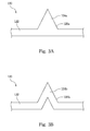
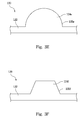
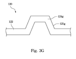
- Fig. 3A to Fig. 3G are schematic diagrams of different embodiments of back sheets of the invention. In each of Figs. 3A to 3G , only a portion of the back sheet 120 including one of the ribs 124 is shown to simplify the description to follow.
- a rib 124a is a solid structure.
- the rib 124a and the substrate 122 can be fabricated by plastic injection.
- a sectional profile of the rib 124a is triangular.
- a side surface 125a of the rib 124a is formed as an oblique surface facing the corresponding solar cell units (see Fig. 1 ).
- a rib 124b is a hollow structure.
- the rib 124b and the substrate 122 can be fabricated by roll forming, plastic injection, or indentation.
- a sectional profile of the rib 124b is triangular, or more precisely, inverted V-shaped due to the hollow structure thereof.
- a side surface 125b of the rib 124b is formed as an oblique surface facing the corresponding solar cell units (see Fig 1 ).
- a rib 124c is a solid structure.
- the rib 124c and the substrate 122 can be fabricated by plastic injection.
- a sectional profile of the rib 124c is bullet-shaped.
- a side surface 125c of the rib 124c is formed as an outwardly curved surface facing the corresponding solar cell units (see Fig. 1 ).
- a rib 124d is a solid structure.
- the rib 124d and the substrate 122 can be fabricated by plastic injection.
- a sectional profile of the rib 124d is roughly conical.
- a side surface 125d of the rib 124d is formed as in inwardly curved surface facing the corresponding solar cell units (see Fig. 1 ).
- a rib 124e is a solid structure.
- the rib 124e and the substrate 122 can be fabricated by plastic injection.
- a sectional profile of the rib 124e is spherical.
- a side surface 125e of the rib 124e is formed as an outwardly rounded surface facing the corresponding solar cell units (see Fig. 1 ).
- a rib 124f is a solid structure.
- the rib 124f and the substrate 122 can be fabricated by plastic injection.
- the sectional profile of the rib 124f is trapezoidal.
- a side surface 125f of the rib 124f is formed as an oblique surface facing the corresponding solar cell units (see Fig. 1 ).
- a rib 124g is a hollow structure.
- the rib 124g and the substrate 122 can be fabricated by plastic or injection indentation.
- the sectional profile of the rib 124g is trapezoidal, or more precisely, inverted U-shaped with outwardly angled sides due to the hollow structure thereof.
- a side surface 125g of the rib 124g is an oblique surface facing the corresponding solar cell units (see Fig. 1 ).
- Fig. 4 is a bar chart of cell to module (CTM) efficiency losses when utilizing different back sheets.
- the chart lists the efficiency losses of solar modules utilizing four different back sheets, namely, a conventional back sheet 120a, a Lambertian surface back sheet 120b, a back sheet 120c having spherical ribs of this disclosure, and a back sheet 120d having triangular ribs of this disclosure.
- the efficiency loss of the solar module utilizing the conventional back sheet 120a without any surface treatment, in which solar cell units 110a are directly disposed on the conventional back sheet 120a reaches 3.5%.
- the efficiency loss of the solar module utilizing the Lambertian surface back sheet 120b having a wavy surface is 1.93%, in which solar cell units 110b are disposed on the Lambertian surface back sheet 120b and the wavy surface is positioned under the solar cell units 110b.
- the solar module of this disclosure utilizing the back sheet 120c having spherical ribs extending between solar cell units 110c is able to raise the usage rate of light, so that the efficiency loss thereof is reduced to 1.89%.
- the solar module utilizing a back sheet 120d having triangular ribs extending between the solar cell units 110d can reflect light to the solar cell units 110d more efficiently, so that the efficiency loss thereof is further reduced to 1.63%.
- Fig. 5A to Fig. 5C are cross-sections of different embodiments of solar modules combined with encapsulant of the invention.
- the encapsulant 118 can be selectively used as required because the ribs 124 have the effect to align.
- the solar module 100 does not include the encapsulant 118.
- the solar cell units 110 can be well positioned between the cover sheet 130 and the back sheet 120 with the ribs 124.
- the encapsulant 118 can be located between the light-receiving surface 112 of each of the solar cell units 110 and the cover sheet 130 in the solar module 100 as required, and the encapsulant 118 is melt and fills the space between the cover sheet 130 and the back sheet 120 during the lamination process.
- the encapsulant 118 can be located between the bottom surface 114 of each of the solar cell units 110 and the back sheet 120, and the encapsulant 118 is melt and may fill the space between the cover sheet 130 and the back sheet 120 during the lamination process.
- the encapsulant 118 can also be disposed both between the light-receiving surface 112 of each of the solar cell units 110 and the cover sheet 130 in the solar module 100 and between the bottom surface 114 of each of the solar cell units 110 and the back sheet 120 as shown in Fig. 2 .
- the ribs on the back sheet can align the solar cell units to maintain a space between the solar cell units and sufficiently prevent the solar cell units from being displaced during lamination process.
Landscapes
- Photovoltaic Devices (AREA)
Applications Claiming Priority (1)
| Application Number | Priority Date | Filing Date | Title |
|---|---|---|---|
| TW100133623A TWI451579B (zh) | 2011-09-19 | 2011-09-19 | 太陽能模組 |
Publications (2)
| Publication Number | Publication Date |
|---|---|
| EP2571062A2 true EP2571062A2 (de) | 2013-03-20 |
| EP2571062A3 EP2571062A3 (de) | 2013-04-03 |
Family
ID=45985191
Family Applications (1)
| Application Number | Title | Priority Date | Filing Date |
|---|---|---|---|
| EP12181389A Withdrawn EP2571062A3 (de) | 2011-09-19 | 2012-08-22 | Solarmodul |
Country Status (4)
| Country | Link |
|---|---|
| US (1) | US20130068289A1 (de) |
| EP (1) | EP2571062A3 (de) |
| CN (1) | CN102437216B (de) |
| TW (1) | TWI451579B (de) |
Cited By (2)
| Publication number | Priority date | Publication date | Assignee | Title |
|---|---|---|---|---|
| WO2016025969A1 (de) | 2014-08-20 | 2016-02-25 | Joanneum Research Forschungsgesellschaft Mbh | Photovoltaikmodul mit integrierter lichtlenkender struktur basierend auf interner totalreflexion |
| WO2017037231A1 (en) * | 2015-09-02 | 2017-03-09 | Sabic Global Technologies B.V. | Solar panel and method of manufacturing such a solar panel |
Families Citing this family (6)
| Publication number | Priority date | Publication date | Assignee | Title |
|---|---|---|---|---|
| CN104269454B (zh) * | 2014-09-28 | 2017-04-26 | 苏州中来光伏新材股份有限公司 | 无主栅、高效率背接触太阳能电池背板、组件及制备工艺 |
| JP6500396B2 (ja) * | 2014-11-13 | 2019-04-17 | トヨタ自動車株式会社 | 太陽電池モジュール |
| TWI609499B (zh) * | 2016-07-01 | 2017-12-21 | 錸德科技股份有限公司 | 太陽能電池模組及其製造方法 |
| US20180309003A1 (en) | 2017-04-24 | 2018-10-25 | Helion Concepts, Inc. | Lightweight solar panels with solar cell structural protection |
| WO2019087600A1 (ja) * | 2017-10-31 | 2019-05-09 | パナソニックIpマネジメント株式会社 | 太陽電池モジュール、構造体取り付け用モジュール、および移動体 |
| CN109509801A (zh) * | 2018-12-27 | 2019-03-22 | 浙江晶科能源有限公司 | 一种双玻光伏组件背面玻璃及双玻光伏组件 |
Citations (1)
| Publication number | Priority date | Publication date | Assignee | Title |
|---|---|---|---|---|
| US4235643A (en) * | 1978-06-30 | 1980-11-25 | Exxon Research & Engineering Co. | Solar cell module |
Family Cites Families (8)
| Publication number | Priority date | Publication date | Assignee | Title |
|---|---|---|---|---|
| US4132570A (en) * | 1977-08-24 | 1979-01-02 | Exxon Research & Engineering Co. | Structural support for solar cell array |
| US4321417A (en) * | 1978-06-30 | 1982-03-23 | Exxon Research & Engineering Co. | Solar cell modules |
| NL9302091A (nl) * | 1993-12-02 | 1995-07-03 | R & S Renewable Energy Systems | Fotovoltaisch zonnepaneel en werkwijze voor het vervaardigen daarvan. |
| US5994641A (en) * | 1998-04-24 | 1999-11-30 | Ase Americas, Inc. | Solar module having reflector between cells |
| JP3259692B2 (ja) * | 1998-09-18 | 2002-02-25 | 株式会社日立製作所 | 集光型太陽光発電モジュール及びその製造方法並びに集光型太陽光発電システム |
| JP2005183840A (ja) * | 2003-12-22 | 2005-07-07 | Kyocera Corp | 太陽電池モジュール |
| US7772484B2 (en) * | 2004-06-01 | 2010-08-10 | Konarka Technologies, Inc. | Photovoltaic module architecture |
| CN2922116Y (zh) * | 2006-01-17 | 2007-07-11 | 义柏科技(深圳)有限公司 | 太阳能晶圆片架 |
-
2011
- 2011-09-19 TW TW100133623A patent/TWI451579B/zh not_active IP Right Cessation
- 2011-11-09 CN CN201110359645.0A patent/CN102437216B/zh not_active Expired - Fee Related
-
2012
- 2012-08-22 EP EP12181389A patent/EP2571062A3/de not_active Withdrawn
- 2012-08-28 US US13/596,230 patent/US20130068289A1/en not_active Abandoned
Patent Citations (1)
| Publication number | Priority date | Publication date | Assignee | Title |
|---|---|---|---|---|
| US4235643A (en) * | 1978-06-30 | 1980-11-25 | Exxon Research & Engineering Co. | Solar cell module |
Cited By (4)
| Publication number | Priority date | Publication date | Assignee | Title |
|---|---|---|---|---|
| WO2016025969A1 (de) | 2014-08-20 | 2016-02-25 | Joanneum Research Forschungsgesellschaft Mbh | Photovoltaikmodul mit integrierter lichtlenkender struktur basierend auf interner totalreflexion |
| AT516194A1 (de) * | 2014-08-20 | 2016-03-15 | Joanneum Res Forschungsgmbh | Photovoltaikmodul mit integrierter lichtlenkender Struktur basierend auf interner Totalreflexion |
| AT516194B1 (de) * | 2014-08-20 | 2017-11-15 | Joanneum Res Forschungsgmbh | Photovoltaikmodul mit integrierter lichtlenkender Struktur basierend auf interner Totalreflexion |
| WO2017037231A1 (en) * | 2015-09-02 | 2017-03-09 | Sabic Global Technologies B.V. | Solar panel and method of manufacturing such a solar panel |
Also Published As
| Publication number | Publication date |
|---|---|
| TW201314922A (zh) | 2013-04-01 |
| US20130068289A1 (en) | 2013-03-21 |
| TWI451579B (zh) | 2014-09-01 |
| CN102437216A (zh) | 2012-05-02 |
| EP2571062A3 (de) | 2013-04-03 |
| CN102437216B (zh) | 2015-06-17 |
Similar Documents
| Publication | Publication Date | Title |
|---|---|---|
| EP2571062A2 (de) | Solarmodul | |
| EP3279949B1 (de) | Solarzellenmodul | |
| JP6624418B2 (ja) | 太陽電池モジュール | |
| JP2013098496A (ja) | 太陽電池モジュールおよびその製造方法 | |
| TW200937649A (en) | Solar cell module and producing method thereof | |
| WO2016031232A1 (ja) | 太陽電池モジュール及び太陽電池モジュールの製造方法 | |
| US12317608B2 (en) | Solar cell and production method thereof, photovoltaic module | |
| CN109560155B (zh) | 太阳能电池组件及其制造方法 | |
| JP5405005B2 (ja) | 太陽電池モジュールの製造方法 | |
| US8895837B2 (en) | Solar cell module | |
| US9196775B2 (en) | Solar battery cell | |
| JP2006156873A (ja) | 樹脂フィルムおよびそれを用いた半導体モジュールの製造方法 | |
| CN106024938A (zh) | 太阳能模组及其制造及返工方法 | |
| JP2011249736A (ja) | 太陽電池モジュールの製造方法 | |
| JP5146390B2 (ja) | 太陽電池モジュールの製造方法及び製造装置 | |
| TWI572133B (zh) | 凹緣集線式太陽能電池模組陣列及其凹緣集線式太陽能電池模組 | |
| JP5524039B2 (ja) | 太陽電池の製造方法 | |
| CN103972307A (zh) | 太阳能电池、其模组及其制造方法 | |
| JP6434895B2 (ja) | 太陽電池モジュール | |
| JP2014013875A (ja) | 太陽電池モジュール及び太陽電池モジュールの製造方法 | |
| JP2011160008A (ja) | 太陽電池モジュール | |
| CN117613123A (zh) | 一种光伏组件上二级管的封装工艺 | |
| JP2018073918A (ja) | 太陽電池モジュールの製造方法 | |
| JP2016100494A (ja) | 配線シート付き裏面電極型太陽電池セル | |
| JP2018056526A (ja) | 太陽電池モジュールの製造方法 |
Legal Events
| Date | Code | Title | Description |
|---|---|---|---|
| PUAL | Search report despatched |
Free format text: ORIGINAL CODE: 0009013 |
|
| PUAI | Public reference made under article 153(3) epc to a published international application that has entered the european phase |
Free format text: ORIGINAL CODE: 0009012 |
|
| 17P | Request for examination filed |
Effective date: 20120822 |
|
| AK | Designated contracting states |
Kind code of ref document: A2 Designated state(s): AL AT BE BG CH CY CZ DE DK EE ES FI FR GB GR HR HU IE IS IT LI LT LU LV MC MK MT NL NO PL PT RO RS SE SI SK SM TR |
|
| AX | Request for extension of the european patent |
Extension state: BA ME |
|
| AK | Designated contracting states |
Kind code of ref document: A3 Designated state(s): AL AT BE BG CH CY CZ DE DK EE ES FI FR GB GR HR HU IE IS IT LI LT LU LV MC MK MT NL NO PL PT RO RS SE SI SK SM TR |
|
| AX | Request for extension of the european patent |
Extension state: BA ME |
|
| RIC1 | Information provided on ipc code assigned before grant |
Ipc: H01L 31/052 20060101ALI20130228BHEP Ipc: H01L 31/048 20060101AFI20130228BHEP |
|
| 17Q | First examination report despatched |
Effective date: 20140520 |
|
| STAA | Information on the status of an ep patent application or granted ep patent |
Free format text: STATUS: THE APPLICATION IS DEEMED TO BE WITHDRAWN |
|
| 18D | Application deemed to be withdrawn |
Effective date: 20160601 |