EP2571159B1 - Motorsteuerungsvorrichtung - Google Patents
Motorsteuerungsvorrichtung Download PDFInfo
- Publication number
- EP2571159B1 EP2571159B1 EP12180975.0A EP12180975A EP2571159B1 EP 2571159 B1 EP2571159 B1 EP 2571159B1 EP 12180975 A EP12180975 A EP 12180975A EP 2571159 B1 EP2571159 B1 EP 2571159B1
- Authority
- EP
- European Patent Office
- Prior art keywords
- motor
- speed
- model
- command
- torque
- Prior art date
- Legal status (The legal status is an assumption and is not a legal conclusion. Google has not performed a legal analysis and makes no representation as to the accuracy of the status listed.)
- Active
Links
Images








Classifications
-
- H—ELECTRICITY
- H02—GENERATION; CONVERSION OR DISTRIBUTION OF ELECTRIC POWER
- H02P—CONTROL OR REGULATION OF ELECTRIC MOTORS, ELECTRIC GENERATORS OR DYNAMO-ELECTRIC CONVERTERS; CONTROLLING TRANSFORMERS, REACTORS OR CHOKE COILS
- H02P23/00—Arrangements or methods for the control of AC motors characterised by a control method other than vector control
- H02P23/04—Arrangements or methods for the control of AC motors characterised by a control method other than vector control specially adapted for damping motor oscillations, e.g. for reducing hunting
-
- G—PHYSICS
- G05—CONTROLLING; REGULATING
- G05B—CONTROL OR REGULATING SYSTEMS IN GENERAL; FUNCTIONAL ELEMENTS OF SUCH SYSTEMS; MONITORING OR TESTING ARRANGEMENTS FOR SUCH SYSTEMS OR ELEMENTS
- G05B19/00—Program-control systems
- G05B19/02—Program-control systems electric
- G05B19/18—Numerical control [NC], i.e. automatically operating machines, in particular machine tools, e.g. in a manufacturing environment, so as to execute positioning, movement or co-ordinated operations by means of program data in numerical form
- G05B19/19—Numerical control [NC], i.e. automatically operating machines, in particular machine tools, e.g. in a manufacturing environment, so as to execute positioning, movement or co-ordinated operations by means of program data in numerical form characterised by positioning or contouring control systems, e.g. to control position from one programmed point to another or to control movement along a programmed continuous path
Definitions
- the present invention relates to a motor control apparatus.
- Control apparatuses for alternating-current (AC) motors generally have a triple-loop configuration.
- a feedback loop of a position control system and a feedback loop of a speed control system constitute a double-loop configuration, combined with a current feedback loop including power conversion by pulse width modulation (PWM) and d-q coordinate system conversion, resulting in a triple-loop configuration.
- PWM pulse width modulation
- a torque command is input from the speed control system.
- Such control systems require accurate, manual adjustment of parameters such as gain and time constant when adapted to particular drive mechanisms with known structures. Additionally, the parameter adjustment needs consideration of various changes in drive mechanisms such as to moment-of-inertia ratio and inertia model, since such changes can occur while the drive mechanisms are in operation depending on their configuration and on applications in which they are used. Thus, the conventional parameter adjustment is significantly complicated and laborious, and this has served as a great inhibitor in the employment of motor control systems. In view of this, recent research and development has focused on "disturbance rejection control", in an attempt to eliminate the need for auto-tuning identification of an unknown or changing moment-of-inertia ratio between the rotor of a motor and a load mechanism, and which ensures that each control system keeps its responses uniform.
- the disturbance rejection control system includes an inertia variation inhibitor to estimate a disturbance torque based on a first torque command and an actual detection speed of the motor. The inertia variation inhibitor then adds the disturbance torque to the first torque command and inputs the sum to the current control system as a second torque command.
- WO2005/093939 discloses a first phase compensator and a second phase compensator.
- the first phase compensator creates a new speed command having a phase advanced by introducing an initial speed command, and then outputs the new speed command.
- the second phase compensator creates a new speed command having a phase advanced by introducing a detection speed of the motor and a torque command, and then outputs the new speed command as an error target command.
- Drive mechanisms driven by motors have mechanical resonance characteristics.
- Mechanical resonance cause vibrations that can occasionally make the motor impossible to drive.
- the mechanical resonance characteristic can be represented by a model of a multi-inertia system using a plurality of masses and springs. In a multi-inertia model, mechanical resonance occurs at different frequencies. There is room for improvement in the art of driving a drive mechanism that involves vibrations caused by such mechanical resonances.
- US 2007/210731A1 discloses a motor control apparatus, comprising: a position detector configured to detect a position of a motor configured to drive a drive mechanism; a speed operator configured to acquire the position of the motor so as to calculate a first speed of the motor; a position controller configured to acquire a difference between the position of the motor and a position command so as to generate and output a first speed command; a speed controller configured to acquire a difference between the first speed command and a second speed of the motor so as to generate and output at least one of a first torque command and a first thrust command, the second speed of the motor comprising a phase advanced relative to a phase of the first speed of the motor; a first phase compensator comprising a first lowpass filter used to advance the phase of the second speed of the motor relative to the phase of the first speed of the motor, the first phase compensator being configured to acquire the first speed and the at least one of the first torque command and the first thrust command so as to output the second speed of the motor, the first lowpass filter comprising a time constant
- a motor control apparatus as defined in claim 1 is provided.
- the dependent claims show some examples thereof.
- a motor control apparatus includes a position detector, a speed operator, a position controller, a speed controller, a first phase compensator, an inertia variation inhibitor, and at least one of a torque controller and a thrust controller.
- the position detector is configured to detect a position of a motor configured to drive a drive mechanism.
- the speed operator is configured to acquire the position of the motor so as to calculate a first speed of the motor.
- the position controller is configured to acquire a difference between the position of the motor and a position command so as to generate and output a first speed command.
- the speed controller is configured to acquire a difference between the first speed command and a second speed of the motor so as to generate and output at least one of a first torque command and a first thrust command.
- the second speed of the motor includes a phase advanced relative to a phase of the first speed of the motor.
- the first phase compensator includes a first lowpass filter used to advance the phase of the second speed of the motor relative to the phase of the first speed of the motor.
- the first phase compensator is configured to acquire the first speed and the at least one of the first torque command and the first thrust command so as to output the second speed of the motor.
- the first lowpass filter includes a time constant calculated using a polynomial including a speed loop gain of the speed controller as an independent variable.
- the inertia variation inhibitor includes a disturbance observer including a resonance inhibition model configured to inhibit a mechanical resonance of the drive mechanism.
- the disturbance observer is configured to estimate at least one of a disturbance torque and a disturbance thrust.
- the inertia variation inhibitor is configured to acquire the first speed and at least one of a second torque command and a second thrust command, configured to add the disturbance torque to the first torque command so as to generate the second torque command or configured to add the disturbance thrust to the first thrust command so as to generate the second thrust command, and configured to output at least one of the second torque command and the second thrust command.
- the torque controller is configured to acquire the second torque command so as to control a torque of the motor.
- the thrust controller is configured to acquire the second thrust command so as to control a thrust of the motor.
- the resonance inhibition model of the disturbance observer comprises an inverse system relative to a resonance inhibition nominal model, the resonance inhibition nominal model comprising a frequency characteristic control device comprising a plurality of time constants determined based on a plurality of frequency set values, the plurality of frequency set values being used to change a change rate of a gain of a frequency characteristic of a rigid body nominal model.
- the apparatus according to the invention ensures highly robust drive control of a motor without adjusting its various parameters, even when the inertia moment or inertial mass and the multi-inertia model of the drive mechanism are unknown or changing.
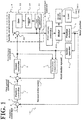
- FIG. 1 shows a motor control apparatus according to this embodiment.
- the motor control apparatus controls a rotation position of a motor based on a position command input from a senior control apparatus, not shown (the rotation position being hereinafter referred to as motor position).
- the motor is a rotation motor.
- a motor control apparatus 100 includes a position controller 1, a speed controller 2, an inertia variation inhibitor 3, a first current controller 4, a position detector 5, a speed operator 6, and a first phase compensator 7.
- the position controller 1 acquires, from a subtractor 8, a position error between the position command and a motor position of a motor 200, which is detected by the position detector 5 as described later. Based on the position error, the position controller 1 outputs a speed command so as to reduce the position error.
- the speed controller 2 acquires, from a subtractor 9, a speed error between the speed command from the position controller 1 and a second motor speed, which has a phase compensated by the first phase compensator 7 as described later. Based on the speed error, the speed controller 2 outputs a first torque command so as to reduce the speed error.
- the inertia variation inhibitor 3 includes a first disturbance observer 31, a lowpass filter 32, a gain multiplier 33, and an adder 34.
- the first disturbance observer 31 calculates an estimate value of a disturbance torque based on a second torque command from the speed controller 2 and based on a rotation speed of the motor 200 output from the speed operator 6 as described later (the rotation speed being hereinafter referred to as first motor speed).
- the lowpass filter 32 removes high frequency noise from the output of the first disturbance observer 31.
- the gain multiplier 33 multiplies the output of the lowpass filter 32 by a predetermined gain and outputs a correction amount of an estimate disturbance torque.
- the adder 34 adds the correction amount of the estimate disturbance torque to the first torque command and outputs the sum as the second torque command.
- the first current controller 4 Based on the second torque command from the inertia variation inhibitor 3, the first current controller 4 outputs, for example, a PWM-controlled drive current to the motor 200.
- the motor 200 uses the drive current from the first current controller 4 to generate a torque with which to drive a load machine 400 through a drive device 300 including a gear.
- the drive device 300 and the load machine 400, as driven by the motor 200 will be collectively referred to as a drive mechanism 500.
- the position detector 5 is made up of, for example, a rotary encoder mechanically coupled to the rotor of the motor 200.
- the position detector 5 detects a motor position, which corresponds to a rotation position of the motor 200.
- the speed operator 6 calculates a first motor speed of the motor 200 based on a change in the motor position of the motor 200 detected by the position detector 5. Specifically, the speed operator 6 may be a differentiator.
- the first phase compensator 7 Based on the first motor speed of the motor 200 output from the speed operator 6 and based on the first torque command output from the speed controller 2, the first phase compensator 7 generates and outputs a new, second motor speed having a phase compensated to advance relative to the phase of the first motor speed.
- the motor control apparatus 100 has a triple-loop configuration including a feedback loop of a position control system, a feedback loop of a speed control system, and a feedback loop of a current control system. Specifically, once a position command is input from the senior control apparatus, not shown, a control signal and a detection signal are transmitted through the feedback loop of the position control system in the order: the position controller 1, the speed controller 2, the first current controller 4, the motor 200, and the position detector 5 (this loop being hereinafter referred to as position control system loop).
- a control signal and a detection signal are transmitted in the order: the speed controller 2, the inertia variation inhibitor 3, the first current controller 4, the motor 200, the position detector 5, the speed operator 6, and the first phase compensator 7 (this loop being hereinafter referred to as speed control system loop).
- the inertia variation inhibitor 3 adjusts a torque command so as to reduce the influence of a disturbance added to the motor 200 through the drive mechanism 500. This ensures robustness in the response characteristic of the motor 200 even when the moment-of-inertia ratio of the drive mechanism 500 is unknown or changing.
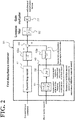
- the first disturbance observer 31 includes a current loop model 41, a resonance inhibition model 43, and equivalent lowpass filters 42a and 42b (each denoted "Equivalent LPF" in FIG. 2 for simplicity).
- FIG. 2 shows the lowpass filter 32 to remove high frequency noise from the output of the first disturbance observer 31, and the gain multiplier 33 to multiply the output of the lowpass filter 32 by a predetermined gain and to output a correction amount of an estimate disturbance torque.
- FIG. 3 is a block diagram illustrating a feedback loop of a disturbance rejection control system, which includes the inertia variation inhibitor 3 (including the first disturbance observer 31 shown in FIG. 2 ), the first current controller 4, the motor 200, and the drive mechanism 500 (the drive device 300 and the load 400) shown in FIG. 1 .
- a control object P(s) (corresponding to the motor 200 and the drive mechanism 500) is represented by the product of a mechanical resonance system R(s) and a mechanical rigid body system P r (s).
- the mechanical rigid body system P r (s) is 1/( J m + J L ) s , where J m denotes a motor inertia moment, J L denotes a load inertia moment, and 1/s denotes an integration element.
- the first disturbance observer 31 includes a current loop model P im (s), a resonance inhibition model P n - 1 (s) , and the equivalent lowpass filters 42a and 42b (each denoted "Equivalent LPF" in FIG. 2 , and not shown in FIG. 3 ).
- a disturbance observer design involves defining a nominal model (reference model), followed by determination of an inverse system relative to the nominal model.
- the resulting disturbance observer includes an inverse system relative to the nominal model.
- the term nominal model (reference model) is defined as a model (a mathematical formula such as a transfer function) that idealizes the control object, which is the drive mechanism including the motor. It is important that the control object nominal model be as simple as possible. In view of this, this embodiment sets the mechanical rigid body system at 1/ Js, which corresponds to the rigid body part of the machine and to the motor.
- this embodiment employs a resonance inhibition nominal model P n (s).
- the resonance inhibition nominal model P n (s), not shown, of this embodiment is represented by the product of a frequency characteristic control device (1 + T 1 s )/(1 + T 2 s ) and a mechanical rigid body system model 1/ J 0 s, which is the control object (the resonance inhibition nominal model being detailed later).
- the mechanical rigid body system model 1/ J 0 s of the control object may not necessarily match the mechanical rigid body system of the control object.
- the first disturbance observer 31 of this embodiment has a resonance model P n - 1 (s).
- the resonance model P n - 1 (s) is an inverse system relative to the resonance inhibition nominal model P n (s), and is an integration of an inverse system (1 + T 2 s )/(1 + T 1 s ) relative to the frequency characteristic control device and an inverse system J 0 s relative to the mechanical rigid body system model of the control object.
- the feedback control system (disturbance rejection control system loop) shown in FIG. 3 has a loop transfer function G Loop represented by Equation (1). With the disturbance rejection control system assumed a closed loop, the entire closed loop from a torque command r to a motor speed v has a closed loop transfer function G Close represented by Equation (2).
- a disturbance observer is designed as a state observer incorporating a disturbance model.
- An observer assuming that the disturbance is constant over time is referred to as a zero-order disturbance observer.
- a minimal-order state observer is used.
- a disturbance observer in the form of a state equation can be represented by an inverse system relative to the nominal model and the lowpass filter of the observer (the lowpass filter being hereinafter referred to as equivalent lowpass filter).
- the equivalent lowpass filter is a first-order lowpass filter, and its band is the frequency band of the disturbance observer.
- the equivalent lowpass filter is a component of the disturbance observer, and this makes the structure of the filter determined accordingly.
- the equivalent lowpass filter is a lowpass filter of second-order in the denominator and first-order in the numerator.
- the equivalent lowpass filter has its parameters determined by the design of the disturbance observer, instead of being determined arbitrarily.
- a higher order means higher disturbance rejection performance.
- extending the band of the disturbance observer in an attempt to improve the disturbance rejection performance, may decrease the control stability of the disturbance rejection control system. This is because of the influence of dynamic characteristics of the first current controller (mainly because of a lowpass characteristic and a control time delay).
- the decreased control stability can cause a peak of frequency characteristic to appear in the high-frequency band. This can cause high-frequency noise from the motor.
- the drive part of the machine driven by the motor has mechanical resonance characteristics. Due to the mechanical resonance characteristics, the dynamic characteristics of the first current controller may have a mechanical resonance influence on the disturbance rejection control system. This is addressed by the first disturbance observer 31 according to this embodiment, which includes the current loop model 41, the resonance inhibition model 43, and the equivalent lowpass filters 42a and 42b.
- a torque command and a motor speed are used as input signals.
- a current controller exists between the torque command and the motor speed.
- the cut-off frequency is sufficiently high relative to the cut-off frequency in the speed control system.
- the transfer function of the current controller may be set at "1" in the design of the disturbance observer.
- the disturbance observer is required to be as low as possible in order, for software installment reasons.
- the speed loop has a cut-off frequency of some tens of hertz and when the load inertia moment is approximately 30 times the motor inertia moment, the compensation of the operation of the drive mechanism requires the disturbance rejection control system to have high response characteristics. This, in turn, requires accurate estimation of the operation of the drive mechanism up to the high-frequency band. This, in turn, requires adding a model of the current controller to the control object, which has been disregarded in the design of the disturbance observer.
- the current loop model 41 eliminates or minimizes an increase in gain of mechanical resonance due to the influence of the loop of the current control system. Specifically, upon input of a second torque command as shown in FIG. 2 , the current loop model 41 outputs the torque signal generated by the motor taking into consideration an approximate delay of the loop of the current control system.
- the resonance inhibition model 43 includes an inverse system 51 relative to the frequency characteristic control device, and a control object inverse model 52.
- the inverse system 51 relative to the frequency characteristic control device controls the frequency characteristic of the first motor speed of the motor 200.
- the control object inverse model 52 multiplies the output (which is the acceleration of the load driven by the motor) of the inverse system 51 relative to the frequency characteristic control device by the inertia moment J 0 of the rotor of the motor 200 and further by the operator s (which is equivalent to a differentiation).
- the resonance inhibition model 43 obtains an acceleration-deceleration torque signal of an ideal motor.
- the acceleration-deceleration torque signal is a torque component used in the acceleration/deceleration of an ideal motor estimated in the nominal model.
- the first disturbance observer 31 obtains an acceleration-deceleration torque signal of an ideal motor at the resonance inhibition model 43 based on the first motor speed of the motor 200. Then, the first disturbance observer 31 passes the acceleration-deceleration torque signal through the equivalent lowpass filter 42b, and at a subtractor 44, subtracts this acceleration-deceleration torque signal from a torque command that is past the current loop model 41 and the equivalent lowpass filter 42a. Thus, the first disturbance observer 31 estimates a disturbance torque. The estimate disturbance torque is adjusted as necessary at the lowpass filter 32 and the gain multiplier 33. The lowpass filter 32 sets a time constant T and removes high frequency noise. The gain multiplier 33 has a predetermined gain. Then, the estimate disturbance torque is output. The equivalent lowpass filters 42a and 42b determine the frequency band of the first disturbance observer 31.
- the resonance inhibition model 43 includes the inverse system 51 relative to the frequency characteristic control device, a multiplier to multiply the inertia moment J 0 , and a differentiator represented an operator s.
- the differentiator including the operator s is a lead element, which cannot be directly installed on a digital circuit and software.
- combining the resonance inhibition model 43 with the equivalent lowpass filters 42a and 42b ensures that the denominator and numerator of the operator s are on the same order.
- Examples of the equivalent lowpass filters 42a and 42b include, but not limited to, second-order filters.
- the inverse system 51 relative to the frequency characteristic control device will be detailed later.
- the first phase compensator 7 includes a control object model 61, a lowpass filter 62, and a control device 63.
- the first phase compensator 7 inputs the first torque command into the control object model 61 and passes its output through the lowpass filter 62 so as to generate a phase compensate signal.
- the first phase compensator 7 subtracts the phase compensate signal from the first motor speed of the motor 200 so as to obtain an error.
- the first phase compensator 7 then passes the error through the control device 63, which feeds the error back to an adder 65 in which the first torque command is input.
- the first phase compensator 7 makes the signal output from the control object model 61 a new speed feedback signal, and outputs the new speed feedback signal as a second motor speed.
- the lowpass filter 62 corresponds to the first lowpass filter recited in the appended claims.
- an error between the speed command output from the position controller 1 and the second motor speed output from the first phase compensator 7 is input into the speed controller 2.
- the first phase compensator 7 as well as estimating the motor speed of the motor 200, works as a phase compensation speed observer to advance the phase of its output.
- advancing the phase of the output in the loop of the speed control system by the first phase compensator 7 ensures an improved phase margin in the loop of the position control system. This ensures stabilize responses and an expanded inertia change range.
- the degree of phase compensation may be set by adjusting the time constant of the lowpass filter 62 of the speed observer. Specifically, it is possible to conduct a simulation or an actual machine test so as to plot optimal values of the time constant of the lowpass filter 62 sequentially on a graph against changes in the speed loop gain in the speed controller 2 (the plotted values are not shown). Then, an approximation may be obtained interpolating the plotted measurement data.
- the speed observer has a lowpass filter time constant T LPF .
- a resonance inhibition nominal model is set with respect to the drive mechanism 500 driven by the motor 200.
- the inverse system 51 relative to the frequency characteristic control device is disposed in the resonance inhibition model 43 (which corresponds to an inverse system relative to the resonance inhibition nominal model) of the first disturbance observer 31.
- the inverse system 51 controls the frequency characteristic of the resonance inhibition nominal model so as to eliminate or minimize vibration caused by mechanical resonance of the motor 200 and the drive mechanism 500.
- the multi-inertia model is among abstract models classified according to the number of inertia elements disposed in the drive mechanism 500 and according to how the inertia elements are coupled together by elasticity elements disposed between the inertia elements.
- Various inertia models exist depending on the configuration of the drive mechanism 500.
- FIG. 5 shows motors 201 of rotation motors.
- a motor 201 has its output shaft coupled to a rigid rotation plate 501 of m 1 mass alone as the drive mechanism 500.
- the inertia model of the drive mechanism 500 is a rigid body model.
- the drive mechanism 500 includes a single inertia element and no elasticity elements.
- a strap 502 is wound around the outer circumference of the rigid rotation plate 501 so as to hang an anchor 503 of m 2 mass.
- the inertia model of the drive mechanism 500 is a two-inertia model.
- the rigid rotation plate 501 ( m 1 ) and the anchor 503 ( m 2 ) are inertia elements, which are coupled together by the strap 502 ( k 1 ) as an elasticity element, resulting in a two-inertia model.
- a ball screw 505 is coupled to the output shaft of the rotation motor 201 through a coupling 504 so as to bring a feed table 506 into linear motion.
- the inertia model of the drive mechanism 500 is a three-inertia model.
- the inertia elements are the ball screw 505 ( m 2 ) including an element 504a ( m 1 ) on the input side of the coupling and an element 504b on the output side of the coupling, and the feed table 506 ( m 3 ).
- the elasticity elements are a coupling portion ( k 1 ) between the coupling 504, and a rolling mechanism ( k 2 ) between the ball screw 50 and the feed table 506.
- n-inertia model will refer to a model with n inertia elements.
- moment-of-inertia ratio refers to a ratio, J L / J 0 , of an inertia moment J L of the entire drive mechanism 500 to the inertia moment J 0 of the rotor including the output shaft of the motor 200, as shown in FIG. 5 .
- the inertia model and the moment-of-inertia ratio of the drive mechanism 500 may change depending on the configuration and application of the drive mechanism 500. Possible examples include when an object to be carried on the feed table of the three-inertia model shown in FIG. 5 has an inertia element and an elasticity element.
- an n-inertia model forms a characteristic curve (n - 1) apex points and (n - 1) bottom points.
- the apex points are resonance points, while the bottom points are anti-resonance points.
- a rigid body model forms a characteristic curve without apex points (resonance points) and bottom points (anti-resonance points), drawing a smoothly decreasing gain.
- a higher moment-of-inertia ratio means a lower gain characteristic (that is, on the decrease in the graph).
- an n-inertia model forms a characteristic curve with "n - 1" phase advance regions. Specifically, the phase characteristic advances in the frequency band between the anti-resonance point and the next resonance point in the gain characteristic.
- the rigid body models of any moment-of-inertia ratios maintain a phase of minus 90 degrees in any frequency band.
- the same n-inertia models may form different characteristic curves depending on the settings of the mass of the inertia elements and the elasticity coefficient of the elasticity elements. Still, the above-described curve characteristics remain unchanged.
- the resonance inhibition nominal model according to this embodiment is close to the characteristic of the rigid body model of a moment-of-inertia ratio of 0 (that is, close to a state without elasticity elements), among the characteristics of the inertia models shown in FIG 6 .
- the resonance inhibition nominal model is slightly higher than the characteristic of the rigid body model of a moment-of-inertia ratio of 0.
- the resonance inhibition nominal model is set to form a characteristic curve with a phase slightly advanced in the center frequency band.
- the first disturbance observer includes the resonance inhibition model 43, which is an inverse system relative to the set resonance inhibition nominal model. This eliminates or minimizes vibration caused by mechanical resonance of the drive mechanism 500. A principle of the mechanical resonance inhibition will be described below.
- a rigid body model is assumed as the nominal model.
- employing a rigid body model as the nominal model minimizes the order of the operator s in the disturbance observer, facilitating its installation.
- An actual drive mechanism 500 oftentimes involves two-or-greater-inertia model, and therefore, the nominal model designed in the form of a rigid body model can easily vibrate due to the mechanical resonance characteristic of the actual drive mechanism 500.
- This can be addressed by adding a notch filter or a lowpass filter in the loop of the disturbance rejection control system including the inertia variation inhibitor 3. This diminishes the mechanical resonance characteristic and stabilizes the disturbance rejection control system.
- the notch filter can cause a phase delay or the lowpass filter can cause gain decrease. This can decrease the disturbance rejection performance, which in turn decreases robustness in relation to changes in the moment-of-inertia ratio.
- this embodiment is concerned with eliminating or minimizing, without a notch filter or a lowpass filter, the influence of mechanical resonance encountered in actual situations.
- the disturbance rejection control is a method of controlling the control object to match its characteristic with the nominal model.
- a control parameter is set to make the gain characteristic (dashed line) of the control object lower than the nominal model (solid line), as in the low-frequency band shown in FIG. 7 .
- the disturbance rejection control uses positive feedback to increase the gain. Stability is ensured in the positive feedback since the loop transfer characteristic G Loop shown in Equation (1) is set at less than 1.
- setting the loop transfer function G Loop shown in Equation (1) at less than 1 ensures continual stability against complicated changes in the gain characteristic and the phase characteristic of the control object in a region lower than the nominal model.
- the apex point of the mechanical resonance is above the nominal model.
- the disturbance rejection control uses negative feedback to lower the gain characteristic.
- the loop transfer characteristic G Loop shown in Equation (1) is equal to or more than 1.
- the phase inherently delays in the control systems and, at the same time, widely changes due to the mechanical resonance characteristic.
- the control systems can go unstable at some frequency at which the loop transfer characteristic G Loop shown in Equation (1) is equal to or more than 1, resulting in a vibration. This is a cause of vibration of the disturbance rejection control system due to the mechanical resonance characteristic of the control object.
- the conditions specified in Finding 1 may be satisfied with respect to any frequency band.
- This is a novel concept distinguished from the conventional practice to merely use a filter for band restriction.
- This embodiment puts this concept into practice using a resonance inhibition nominal model as shown in FIG. 8 , which is a modification of the nominal model.
- the resonance inhibition nominal model has different inclinations from the nominal model at frequencies f 1 and f 2 . This makes the gain of the mechanical resonance characteristic lower than the resonance inhibition nominal model. Appropriate frequencies f 1 and f 2 are selected to sandwich the apex point of the mechanical resonance characteristic. This ensures continual stability of the control systems against changes in the mechanical resonance characteristic.
- the resonance inhibition nominal model may include the frequency characteristic control device (1 + T 1 s )/(1 + T 2 s ) and the mechanical rigid body system model 1/ J 0 s of the control object.
- the resonance inhibition model is configured as an integration of an inverse system (1 + T 2 s )/(1 + T 1 s ) relative to the frequency characteristic control device and an inverse system J 0 s that is relative to the mechanical rigid body system model of the control object and that is relative to the mechanical rigid body system.
- the conditions under which a mechanical resonance can occur include when both the gain characteristic and the phase characteristic have low margins at the same time. This is, specifically, when the loop transfer characteristic G Loop shown in Equation (1) of the disturbance rejection control system loop including the inertia variation inhibitor 3 has a phase reaching minus 180 degrees, and when the gain is as high as in excess of 1, causing a vibration to occur. It is therefore difficult to design the resonance inhibition nominal model so that either the gain characteristic or the phase characteristic has a complete margin with respect to any frequency band. Still, such a design is possible that both the gain characteristic and the phase characteristic have margins approximately at the same time. Specifically, even when one of the gain characteristic and the phase characteristic may have a low margin locally in some frequency band, the other characteristic can secure a sufficient margin in the frequency band.
- the resonance inhibition model 43 includes the inverse system 51 relative to the frequency characteristic control device.
- the inverse system 51 controls the loop transfer characteristic G Loop shown in Equation (1) of the disturbance rejection control system loop to have a phase of minus 180 degrees and a gain of less than 1 in the low-frequency band.
- the inverse system 51 controls the loop transfer characteristic G Loop to have a phase other than minus 180 degrees (that is, at a phase higher or lower than minus 180 degrees).
- An example of the inverse system 51 relative to the frequency characteristic control device according to this embodiment is represented by the transfer function (1 + T 2 s )/(1 + T 1 s ), as shown in FIG. 2 .
- the two time constants T 1 and T 2 may be set conveniently taking into consideration any drive mechanisms 500 as possible control objects.
- the inverse system 51 (1 + T 2 s )/(1 + T 1 s ), relative to the frequency characteristic control device has the two time constants T 1 and T 2 respectively set at 1/2 ⁇ f 1 and 1/2 ⁇ f 2 .
- Setting the spacing between f 1 and f 2 wide accommodates to changes in the mechanical resonance frequency to some degree, and also accommodates to control objects of various multi-inertia models.
- the time constants T 1 and T 2 of the inverse system 51 relative to the frequency characteristic control device are based on a nominal model of a rigid body.
- the time constants T 1 and T 2 are respectively determined by a plurality of frequency set values f 1 and f 2 used to change the change rate of gain of the frequency characteristic of the nominal model.
- the loop transfer characteristic G Loop can go unstable.
- the gain characteristic of the resonance inhibition nominal model is set to maintain an appropriate difference of elevation (feedback amount) against the gain characteristic of the control object in any frequency band.
- the resonance inhibition nominal model including the frequency characteristic control device has the frequency characteristic shown in FIG. 6 .
- the apex points of some mechanical resonance characteristics exceed above the resonance inhibition nominal model, thereby reducing its gain margin.
- the phase characteristic of the resonance inhibition nominal model advances to a large degree in the bands where the resonance inhibition nominal model is exceeded in the gain characteristic diagram.
- the reduced gain margins are compensated for on the part of the phase margin.
- the resonance inhibition model 43 may estimate a disturbance torque. This ensures a gain margin and a phase margin that are sufficient as a whole with respect to any multi-inertia models, in eliminating or minimizing mechanical resonance.
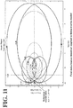
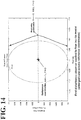
- the stability of the disturbance rejection control system loop may be determined using Nyquist diagrams shown in FIGs. 9 to 14 .
- the Nyquist diagrams of FIGs. 9 , 11 , and 13 indicate stability of the closed loop transfer function G Close shown in Equation (2) using polar coordinates on a complex plane of the frequency characteristic of the open loop transfer function shown in Equation (1).
- FIGs. 11 and 12 show the case of a three-inertia model
- FIGs. 13 and 14 show the case of a four-inertia model
- FIGs. 11 and 12 and FIGs. 13 and 14 indicate that the control loop of the disturbance rejection control system is stable both in the three-inertia model and the four-inertia model, similarly to the two-inertia model.
- the feedback control systems in the Nyquist diagrams of FIGs. 9 to 14 are the same systems with the same control parameters. This indicates stability in any of the two- to four-inertia models without individual adjustments.
- FIGs. 15 to 20 show Nyquist diagrams of conventional disturbance rejection control systems.
- FIGs. 15 and 16 show the case of a two-inertia model
- FIGs. 19 and 20 show the case of a four-inertia model, both ensuring stability.
- FIGs. 17 and 18 show the case of a three-inertia model.
- the vector locus surrounds the reference coordinates.
- the reference coordinates are positioned to the right with respect to the surrounding vector locus as viewed in the forward direction in which the angular frequency ⁇ increases. This indicates that the conventional disturbance rejection control system loop applied to the three-inertia model goes unstable, causing a vibration.
- the first disturbance observer 31 according to this embodiment and the resonance inhibition model 43 disposed in the first disturbance observer 31 have novel configurations distinguished from the background art. This enables the first disturbance observer 31 and the resonance inhibition model 43 to eliminate or minimize vibration caused by mechanical resonance.
- FIGs. 21 to 26 show specific step response data.
- the term “Position Error” shown in the graphs denotes an error between the position command from the senior control apparatus, not shown, and the motor position from the position detector 5. The error is a signal directly input into the position controller 1 (see A in FIG. 1 , which applies throughout the description).
- the term “Speed” shown in the graphs denotes a speed component (differentiated value of the position command) of the position command that the motor control apparatus 100 acquires, and also denotes the first speed that the speed operator 6 outputs (which applies throughout the description).
- Torque shown in the graphs denotes the second torque command that is output by the inertia variation inhibitor 3 and is about to be input into the first current controller 4 (see B in FIG. 1 , which applies throughout the description).
- the change inhibition effect of this embodiment with respect to the motor speed and the torque command might seem unclear in the comparison between the two-inertia model of this embodiment shown in FIG. 22 and the two-inertia model of the comparative example shown in FIG. 21 .
- the change inhibition effect of this embodiment is clearly seen in the comparison between the three-inertia model of this embodiment shown in FIG. 24 and the three-inertia model of the comparative example shown in FIG. 23 , and in the comparison between the four-inertia model of this embodiment shown in FIG. 26 and the four-inertia model of the comparative example shown in FIG. 25 . This indicates that this embodiment improves robustness against mechanical resonance.
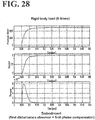
- FIGs. 27 to 30 show graphs of simulations conducted at different moment-of-inertia ratios, for comparison between this embodiment and comparative examples. All the cases employ rigid body models. FIGs. 27 to 30 indicate that this embodiment exhibits a change inhibition effect with respect to the torque command irrespective of the moment-of-inertia ratio. Thus, this embodiment maintains robustness against the moment-of-inertia ratio.
- FIG. 31 shows ideal waveforms in standard P-PI control of a rigid body model of a high moment-of-inertia ratio.
- FIG. 32 shows graphs of a simulation according to this embodiment under conditions similar to those in FIG. 31 . ( FIG. 32 is identical to FIG. 30 .)
- a comparison between FIGs. 31 and 32 reveals that the waveforms of this embodiment resemble the ideal waveforms particularly at the parts surrounded by broken lines in FIG. 31 , and that this embodiment is preferable in standard P-PI control applications.
- the motor control apparatus 100 has a triple-loop configuration including the loop of the position control system, the loop of the speed control system, and the loop of the current control system.
- the inertia variation inhibitor 3 uses the first disturbance observer 31 to estimate the disturbance torque of the motor 200, adds the estimated disturbance torque to the first torque command, and outputs the sum as the second torque command. This ensures robustness against the control characteristics of the motor 200 even when the moment-of-inertia ratio of the drive mechanism 500 is unknown or changing.
- the first phase compensator 7 disposed in the loop of the speed control system works as a phase compensation speed observer to advance the phase, as well as estimating the speed. In this manner, the first phase compensator 7 advances the phase of the speed control system and improves the phase margin of the position control system, thereby improving the response characteristic of the inertia variation inhibitor 3. That is, robustness improves against the moment-of-inertia ratio of the drive mechanism 500.
- the first disturbance observer 31 estimates a disturbance torque in the inertia variation inhibitor 3.
- the first disturbance observer 31 includes the resonance inhibition model 43.
- the resonance inhibition model 43 outputs an acceleration-deceleration torque signal of an ideal motor in response to the first motor speed of the motor 200.
- the acceleration-deceleration torque signal has minimal influence of mechanical resonance of the drive mechanism 500.
- the first disturbance observer 31 uses the acceleration-deceleration torque signal of the ideal motor to estimate the disturbance torque.
- the inertia variation inhibitor 3 eliminates or minimizes fluctuation of inertia moment of the drive mechanism without vibration caused by mechanical resonance of the drive mechanism 500. This ensures robustness against the control characteristics of the motor 200 even when the inertia model of the drive mechanism 500 is unknown or changing.
- this embodiment ensures drive control of the motor 200 with high robustness without adjusting various parameters, even when both the inertia moment and multi-inertia model of the drive mechanism 500 are unknown or changing.
- This embodiment also highly improves resistance against mechanical resonance (that is, eliminates or minimizes the tendency toward vibration), which has been considered difficult to realize by conventional disturbance rejection control systems.
- the resonance inhibition model 43 can be fixed in any convenient design, and this ensures use of fixed control systems and fixed parameters to operate control objects of complicated mechanical resonance characteristics without adjustments.
- Conventional motor control apparatuses involve individual adjustment, manual or automatic, of control gain in accordance with the mechanical characteristics of the drive mechanism 500. It is after this adjustment that the drive mechanism 500 can operate. That is, many conventional motor control apparatuses have been considered high in performance but difficult to handle, which has discouraged their introduction.
- This embodiment facilitates utilization of motor control apparatuses in a widened range of applications. This embodiment also significantly shortens the time necessary for setting up mechanical machines, which is a significant advantage in the utilization of motor control apparatuses.
- the resonance inhibition model 43 is an inverse system relative to the resonance inhibition nominal model proposed in this embodiment.
- the resonance inhibition nominal model includes a frequency characteristic control device (1 + T 1 s )/(1 + T 2 s ), not shown.
- the frequency characteristic control device includes the plurality of time constants T 1 and T 2 , which are respectively determined by the plurality of frequency set values f 1 and f 2 used to change the change rate of gain of the frequency characteristic of the rigid nominal model.
- Appropriately setting the plurality of time constants of the frequency characteristic control device ensures design of the resonance inhibition nominal model such that the resonance inhibition nominal model is based on the mechanical resonance characteristic of the control object and is deformed to a degree that ensures resonance inhibition. This ensures design of the resonance inhibition nominal model and the resonance inhibition model 43 in accordance with possible control objects (the motor 200 and the drive mechanism 500).
- the plurality of time constants T 1 and T 2 are set to control the resonance inhibition nominal model to maintain, in any frequency band, at least one of the gain margin and the phase margin on the frequency characteristic of the resonance inhibition nominal model against the mechanical resonance characteristics of the motor 200 and the drive mechanism 500.
- the plurality of time constants T 1 and T 2 are determined by the frequency set values f 1 and f 2 .
- Appropriately setting the time constants T 1 and T 2 changes the inclination of the rigid body nominal model to result in the resonance inhibition nominal model.
- Such a resonance inhibition nominal model has generally higher gain than the mechanical resonance characteristic of the control object.
- Appropriately setting the plurality of time constants T 1 and T 2 also provides the following advantage.
- the apex points of some mechanical resonance characteristics might exceed above the resonance inhibition nominal model on the gain characteristic part, thereby reducing its gain margin. In the phase characteristic part, however, the phase characteristic of the resonance inhibition nominal model advances to a large degree in the bands where the resonance inhibition nominal model is exceeded in the gain characteristic part.
- the frequency characteristic control device is designed to control the resonance inhibition nominal model to maintain at least one of the gain margin and the phase margin on the frequency characteristic against the mechanical resonance characteristic of the control object.
- the resonance inhibition nominal model including this frequency characteristic control device, an inverse system relative to the resonance inhibition nominal model is used as a resonance inhibition model to estimate the disturbance torque. This ensures a gain margin and a phase margin that are sufficient as a whole with respect to any multi-inertia models, in eliminating or minimizing mechanical resonance.
- the resonance inhibition model 43 of the first disturbance observer 31 includes the inverse system 51 relative to the frequency characteristic control device (1 + T 2 s )/(1 + T 1 s ).
- the plurality of time constants T 1 and T 2 are set to control the loop transfer characteristic G Loop (Equation (1)) of the contain disturbance rejection control system loop including the inertia variation inhibitor 3, the first current controller 4, the motor 200, and the drive mechanism 500.
- the loop transfer characteristic G Loop is controlled to maintain a phase of minus 180 degrees and a gain of less than 1 in the low-frequency band.
- the loop transfer characteristic G Loop is controlled to maintain a phase other than minus 180 degrees.
- the inverse system 51 relative to the frequency characteristic control device controls the frequency characteristic of the motor speed of the motor 200.
- the inverse system 51 relative to the frequency characteristic control device outputs a signal corresponding to speed.
- the signal is multiplied by the inertia moment J 0 and differentiated by the operator s, thereby being converted into a signal corresponding to torque. This ensures that the resonance inhibition model 43 outputs an acceleration-deceleration torque signal of the ideal motor, with minimal influence of mechanical resonance.
- the inertia moment J 0 is an inertia moment of the rotor of the motor 200, and thus the load of the entire drive mechanism 500 can be regarded as a disturbance element. This ensures that at the time of shipment from the factory, the motor control apparatus 100 undergoes adjustment of its parameters (such as time constant, attenuation coefficient, and various kinds of gain) in accordance with what kind of motor 200 to apply as the control object. This eliminates the need for parameter adjustment of the drive mechanism 500 to be driven by the motor 200.
- the frequency characteristic control device is a component of the resonance inhibition nominal model. The frequency characteristic control device is defined by the function (1 + T 1 s )/(1 + T 2 s ).
- the function includes the plurality of variable time constants T 1 and T 2 , which are respectively determined by the frequency set values f 1 and f 2 .
- the disturbance rejection control system uses the resonance inhibition model, which is an inverse system relative to the resonance inhibition nominal model. This ensures a gain margin and a phase margin that are sufficient as a whole with respect to any multi-inertia models, and eliminates or minimizes fluctuation of inertia moment of the drive mechanism without mechanical resonance.
- the first disturbance observer 31 subtracts the acceleration-deceleration torque signal of the ideal motor from the second torque command so as to estimate the disturbance torque.
- the acceleration-deceleration torque signal is obtained from the resonance inhibition model 43 based on the first motor speed of the motor 200, and has minimal influence of mechanical resonance.
- the current loop model 41 of the first disturbance observer 31 processes the second torque command equally with the first current controller 4. This reduces the phase difference between the acceleration-deceleration torque signal of the ideal motor (torque signal calculated from the motor speed) obtained by the resonance inhibition model 43 and the torque signal (as a command) output from the current loop model. This ensures accurate estimation of the disturbance torque, and improves the response characteristic of the inertia variation inhibitor 3. This, in turn, improves the cut-off frequency of the loop of the speed control system up to the high-frequency band, thus accommodating to greater moment-of-inertia ratios. That is, robustness improves against the moment-of-inertia ratio of the drive mechanism 500.
- the above-described embodiment employs the first phase compensator 7 to advance the phase of the speed control system, thereby improving the phase margin of the position control system. It is also possible to employ a second phase compensator to advance the phase in a particular frequency band. This further improves the phase margin of the position control system.
- FIG. 33 shows a first modification of the above-described embodiment shown in FIG. 1 .
- a motor control apparatus 100A according to the first modification includes a new, second phase compensator 11 between the position controller 1 and the subtracter 9.
- the second phase compensator 11 acquires a first speed command output from the position controller 1, advances the phase of the first speed command in a particular frequency band, and outputs a second speed command to the subtractor 9.
- the second phase compensator 11 includes a lowpass filter 71, a highpass filter 72, and an adder 73.
- the outputs of the lowpass filter 71 and the highpass filter 72 are added by the adder 73, which then outputs the sum.
- the second phase compensator 11 may be a control block using a phase advance filter.
- the phase advance filter has a transfer function G(s) represented by Equation (3).
- the lowpass filter has a time constant T L
- the highpass filter has a time constant T H .
- the time constants T L and T H are set to satisfy the relationship: 1/ T H ⁇ 1/ T L .
- the cutoff frequencies ⁇ 1 and ⁇ 2 are set to satisfy the relationship: ⁇ 2 ⁇ ⁇ 1 . This helps correct phase delay. If these conditions are reversed, a phase delay filter results, providing no phase advance effect.
- the phase advance filter may also be represented by Equation (4).
- G s ⁇ L / ⁇ L + s + T L ⁇ H s / ⁇ H + s
- the second phase compensator 11 inputs the first speed command from the position controller 1 into the lowpass filter 71 and the highpass filter 72, adds the outputs of the lowpass filter 71 and the highpass filter 72 at the adder 73, and outputs the sum as the second speed command.
- Using the lowpass filter 71 alone might not advance the phase, while using the highpass filter 72 alone might advance the phase in the undesired, low-frequency band. Additionally, the highpass filter 72 might cause decrease of gain in the low-frequency band. The gain in the low-frequency band is inherently compensated for by speed loop gain or speed integration.
- the second phase compensator 11 according to this embodiment shown in FIG. 34 , however, works as a phase advance filter to advance the phase only in a desired frequency band.
- the lowpass filter 71 corresponds to the second lowpass filter recited in the accompanying claims.
- the second phase compensator 11 may change the cutoff frequencies of the lowpass filter 71 and the highpass filter 72 in accordance with the speed loop gain in the speed controller 2. Specifically, it is possible to conduct a simulation or an actual machine test so as to plot optimal values of the cutoff frequencies of the lowpass filter 71 and the highpass filter 72 sequentially on a graph against changes in the speed loop gain in the speed controller 2 (the plotted values are not shown). Then, an approximation may be obtained interpolating the plotted measurement data.
- a polynomial of approximation using the speed loop gain K v as an independent variable may be used to appropriately change the cutoff frequency of the lowpass filter 71 or the highpass filter 72 of the second phase compensator 11. This ensures automatic re-adjustment of the compensation value of the phase.
- FIGs. 35 , 36 , and 37 respectively correspond to FIGs. 22 , 24 , and 26 of the above-described embodiment.
- the first modification exhibits a clear change inhibition effect compared with the comparative examples shown in FIGs. 21 , 23 , and 25 . That is, the first modification improves robustness against mechanical resonance with respect to any inertia models.
- FIGs. 38 to 43 show graphs of experimental tests conducted at different moment-of-inertia ratios, for comparison between the first modification and comparative examples.
- the position command is sequentially varied.
- FIGs. 38 to 43 indicate that in the comparative examples of FIGs. 38 , 40 , and 42 , as the moment-of-inertia ratio becomes greater, the torque command is more likely to vibrate.
- the first modification of FIGs. 39 , 41 , and 43 exhibits a change inhibition effect with respect to the torque command irrespective of the moment-of-inertia ratio, providing significantly high stability.
- the first modification provides high robustness against the moment-of-inertia ratio.
- the motor control apparatus 100A includes the second phase compensator 11 in the loop of the position control system.
- the second phase compensator 11 works as a phase advance filter to improve the phase margin of the position control system, which in turn improves the response characteristic of the inertia variation inhibitor 3. That is, robustness improves against the moment-of-inertia ratio of the drive mechanism 500.
- the current loop model 41 is disposed in the first disturbance observer 31 to decrease the delay of the current loop relative to the torque command. This, however, should not be construed in a limiting sense. It is also possible to provide a phase compensation current observer, not shown, in the current controller to decrease the delay of the current loop, so as to improve the response characteristic of the inertia variation inhibitor 3.
- FIG. 44 shows a second disturbance observer 31A.
- the second disturbance observer 31A is different from the first disturbance observer 31 shown in FIG. 2 in that no current loop model 41 is provided (as indicated by the broken line). Instead, a current loop inverse model 41A is provided on the output side of the resonance inhibition model 43.
- the current loop inverse model 41A is an inverse system relative to the current loop model 41. If, for example, the denominator and the numerator of the transfer function are reversed, the operator s of the numerator has a higher order than the order of the denominator, making it impossible to implement the current loop inverse model 41A.
- the lowpass filter 32 outside the second disturbance observer 31A and an additional lowpass filter 32, not shown, may be moved inside the second disturbance observer 31A and disposed along the respective two paths on the input side of the subtractor 44.
- One of the lowpass filters 32 may multiply the current loop inverse model 41A to reduce the order of the numerator of the transfer function of the inverse model.
- the current loop inverse model 41A advances the phase of the acceleration-deceleration torque signal of the ideal motor (the phase of the torque signal calculated from the motor speed) output from the resonance inhibition model 43.
- the current loop inverse model 41A reduces the phase difference between the second torque command (a torque signal as a command) and the acceleration-deceleration torque signal of the ideal motor (the torque signal calculated from the motor speed) obtained by the resonance inhibition model 43. This ensures accurate estimation of the disturbance torque.
- the current loop model 41 has a function of phase advance compensation.
- An ideal current loop inverse model 41A relative to an actual current control system P i (s) is P i -1 (s) .
- a phase advance compensator as simple as (1 + T 4 s )/(1 + T 3 s ) is used. Since this is the case of advance compensation, the time constants satisfy: T 3 ⁇ T 4 . This decreases the delay of the actual current control system P i (s) and approximates the transfer function to its ideal form "1".
- G Close s P i s R s 1 J m + J L s 1 ⁇ K f g s 1 ⁇ R s 1 + T 2 s 1 + T 1 s 1 + T 4 s 1 + T 3 s J m J L + J m
- FIGs. 45 , 46 , and 47 respectively correspond to FIGs. 22 , 24 , and 26 of the above-described embodiment.
- the second modification exhibits a clear change inhibition effect compared with the comparative examples shown in FIGs. 21 , 23 , and 25 . That is, the second modification improves robustness against mechanical resonance with respect to any inertia models.
- the second modification employs both the first phase compensator 7 and the second phase compensator 11, similarly to the first modification.
- FIGs. 48 to 53 show graphs of simulations conducted at different moment-of-inertia ratios, for comparison between the first modification and the second modification.
- FIGs. 48 to 53 indicate that as the moment-of-inertia ratio becomes greater, FIGs. 49 , 51 , and 53 of the second modification is superior to FIGs. 48 , 50 , and 52 of the first modification in terms of the change inhibition effect with respect to the motor speed of the motor 200 and the torque command (particularly at the parts surrounded by broken lines).
- the motor control apparatus 100B employs the current loop inverse model 41A to carry out phase advance compensation. This decreases the delay of the actual current control system and approximates the transfer function to its ideal form. This ensures that even when the transfer function of the current loop of the second disturbance observer 31A approximates to "1", the error with respect to the actual current control system is small. This ensures a wide band design of the second disturbance observer 31A, and improves the response characteristic of the inertia variation inhibitor 3. That is, robustness further improves against the moment-of-inertia ratio of the drive mechanism 500.
- the motor 200 is a rotation motor, this should not be construed in a limiting sense. It is also possible to employ a linear motor.
- torque-related terminology is replaced with thrust
- inertia moment-related terminology is replaced with inertial mass
- the rotary encoder is replaced with linear scale
- the integration rotation position is replaced with integration motion position
- the rotor is replaced with mover.
Landscapes
- Engineering & Computer Science (AREA)
- Power Engineering (AREA)
- Human Computer Interaction (AREA)
- Manufacturing & Machinery (AREA)
- Physics & Mathematics (AREA)
- General Physics & Mathematics (AREA)
- Automation & Control Theory (AREA)
- Control Of Electric Motors In General (AREA)
Claims (7)
- Eine Motor-Steuerungsvorrichtung, gekennzeichnet durch:einen Positionsdetektor (5), der eingerichtet ist, um eine Position eines Motors zu detektieren, welcher zum Antreiben eines Antriebsmechanismus (500) eingerichtet ist;eine Drehzahl-Bedienvorrichtung (6), die eingerichtet ist zum Erhalten der Position des Motors, um eine erste Drehzahl des Motors zu berechnen;eine Position-Steuereinheit (1), die eingerichtet ist zum Erhalten einer Differenz zwischen der Position des Motors und einem Positionsbefehl, um einen ersten Drehzahlbefehl zu erzeugen und auszugeben;eine Drehzahl-Steuereinheit (2), die eingerichtet ist zum Erhalten einer Differenz zwischen dem ersten Drehzahlbefehl und einer zweiten Drehzahl des Motors, um mindestens einen von einem ersten Drehmomentbefehl und einem ersten Schubbefehl zu erzeugen und auszugeben, wobei die zweite Drehzahl des Motors eine Phase aufweist, die relativ zu einer ersten Drehzahl des Motors vorverschoben ist;einen ersten Phasenkompensator (7), der einen ersten Tiefpassfilter (62) aufweist, welcher verwendet wird, um die Phase der zweiten Drehzahl des Motors relativ zu der Phase der ersten Drehzahl des Motors vorzuverschieben, wobei der erste Phasenkompensator (7) eingerichtet ist zum Erhalten der ersten Drehzahl und des mindestens einen von dem ersten Drehmomentbefehl und dem ersten Schubbefehl, um die zweite Drehzahl des Motors auszugeben, wobei der erste Tiefpassfilter (62) eine Zeitkonstante aufweist, die unter Verwendung eines Polynoms berechnet wird, das eine Drehzahl-Schleifenverstärkung (33) der Drehzahl-Steuereinheit (2) als eine unabhängige Variable aufweist;eine Trägheitsvariation-Unterdrückungseinheit (3), welche einen Störungsüberwacher (31; 31A) aufweist, wobei der Störungsüberwacher (31, 31A) eingerichtet ist zum Schätzen von mindestens einem von einem Stördrehmoment und einem Störschub, wobei die Trägheitsvariation-Unterdrückungseinheit (3) eingerichtet ist, um die erste Drehzahl und mindestens einen von einem zweiten Drehmomentbefehl und einem zweiten Schubbefehl zu erhalten, eingerichtet ist, um das Stördrehmoment zu dem ersten Drehmomentbefehl zu addieren, um den zweiten Drehmomentbefehl zu erzeugen, oder eingerichtet ist, um den Störschub zu dem ersten Schubbefehl zu addieren, um den zweiten Schubbefehl zu erzeugen, und eingerichtet ist, um mindestens einen von dem zweiten Drehmomentbefehl und dem zweiten Schubbefehl auszugeben; undmindestens eine von einer Drehmoment-Steuereinheit (4; 4A) und einer Schub-Steuereinheit (4; 4A), wobei die Drehmoment-Steuereinheit (4; 4A) eingerichtet ist zum Erhalten des zweiten Drehmomentbefehls, um ein Drehmoment des Motors zu steuern, wobei die Schub-Steuereinheit (4; 4A) eingerichtet ist zum Erhalten des zweiten Schubbefehls, um einen Schub des Motors zu steuern,dadurch gekennzeichnet, dassder Störungsüberwacher (31; 31A) ein Resonanz-Unterdrückungsmodell (43) aufweist, welches eingerichtet ist, um eine mechanische Resonanz des Antriebsmechanismus (500) zu unterdrücken,wobei das Resonanz-Unterdrückungsmodell (43) des Störungsüberwachers (31; 31A) ein inverses System relativ zu einem nominalen Resonanz-Unterdrückungsmodell aufweist, wobei das nominale Resonanz-Unterdrückungsmodell eine Frequenzkennlinie-Steuerungsvorrichtung aufweist, welche eine Mehrzahl von Zeitkonstanten aufweist, die basierend auf einer Mehrzahl festgelegter Frequenzwerte ermittelt werden, wobei die Mehrzahl festgelegter Frequenzwerte verwendet wird, um eine Änderungsrate einer Verstärkung (33) einer Frequenzkennlinie eines nominalen Modells eines starren Körpers zu ändern.
- Die Motor-Steuerungsvorrichtung gemäß Anspruch 1, wobei die Mehrzahl von Zeitkonstanten der Frequenzkennlinie-Steuerungsvorrichtung festgelegt sind, um das nominale Resonanz-Unterdrückungsmodell zu steuern, sodass, in jedem Frequenzband, mindestens eine von einer Verstärkungsspanne und eine Phasenspanne auf einer Frequenzkennlinie relativ zu einer mechanischen Resonanzkennlinie des Motors und des Antriebsmechanismus (500) beibehalten wird.
- Die Motor-Steuerungsvorrichtung gemäß Anspruch 1 oder 2,
wobei das Resonanz-Unterdrückungsmodell (43) des Störungsüberwachers (31; 31A) ein inverses System relativ zu der Frequenzkennlinie-Steuerungsvorrichtung aufweist,
wobei die Trägheitsvariation-Unterdrückungseinheit (3), die mindestens eine von der Drehmoment-Steuereinheit (4; 4A) und der Schub-Steuereinheit (4; 4A), der Motor und der Antriebsmechanismus (500) gemeinsam eine Störungsrückweisung-Steuersystem-Schleife bilden, die eine Schleife-Übertragungskennlinie aufweist,
wobei die Mehrzahl von Zeitkonstanten der Frequenzkennlinie-Steuerungsvorrichtung festgelegt sind, um die Schleife-Übertragungskennlinie zu steuern, sodass sie eine Phase von minus 180 Grad und eine Verstärkung (33) von weniger als 1 in einem Niederfrequenzband aufweist, und eine von minus 180 Grad verschiedene Phase in einem Frequenzbereich eines Hochfrequenzbands, dass eine Verstärkung (33) von gleich oder mehr als 1 bereitstellt, aufweist, und
wobei das Resonanz-Unterdrückungsmodell (43) des Störungsüberwachers (31; 31A) eingerichtet ist, um einen Wert der ersten Drehzahl des Motors durch das inverse System relativ zu der Frequenzkennlinie-Steuerungsvorrichtung zu erhalten, eingerichtet ist, um den erhaltenen Wert mit mindestens einem von einem Trägheitsmoment und einer Trägheitsmasse des Motors zu multiplizieren, und eingerichtet ist, um ein durch die Multiplikation erhaltenes Produkt zu differenzieren. - Die Motor-Steuerungsvorrichtung gemäß irgendeinem der Ansprüche 1 bis 3, wobei der Störungsüberwacher (31; 31A) eingerichtet ist, um ein Beschleunigung-Abbrems-Drehmomentsignal eines idealen Motors von dem zweiten Drehmomentbefehl zu subtrahieren, und eingerichtet ist, um eine durch die Subtraktion erhaltene Differenz als das Stördrehmoment auszugeben, oder der Störungsüberwacher (31, 31A) eingerichtet ist, um ein Beschleunigung-Abbrems-Schubsignal des idealen Motors von dem zweiten Schubbefehl zu subtrahieren, und eingerichtet ist, um eine durch die Subtraktion erhaltene Differenz als den Störschub auszugeben, wobei das Beschleunigung-Abbrems-Drehmomentsignal und das Beschleunigung-Abbrems-Schubsignal basierend auf der ersten Drehzahl unter Verwendung des Resonanz-Unterdrückungsmodells (43) berechnet werden.
- Die Motor-Steuerungsvorrichtung gemäß irgendeinem der Ansprüche 1 bis 3,
wobei der Störungsüberwacher (31; 31A) ferner ein Stromschleifenmodell (41) aufweist, das eine Stromsteuerschleife der mindestens einen von der Drehmoment-Steuereinheit (4; 4A) und der Schub-Steuereinheit (4; 4A) simuliert, und
wobei der Störungsüberwacher (31; 31A) eingerichtet ist, um einen Wert des zweiten Drehmomentbefehls durch das Stromschleifenmodell (41) zu erhalten, eingerichtet ist, um ein Beschleunigung-Abbrems-Drehmomentsignal eines idealen Motors von dem erhaltenen Wert zu subtrahieren, und eingerichtet ist, um eine durch die Subtraktion erhaltene Differenz als das Stördrehmoment auszugeben, oder der Störungsüberwacher (31; 31A) eingerichtet ist, um einen Wert des zweiten Schubbefehls durch das Stromschleifenmodell (41) zu erhalten, eingerichtet ist, um ein Beschleunigung-Abbrems-Schubsignal des idealen Motors von dem erhaltenen Wert zu subtrahieren, und eingerichtet ist, um eine durch das Subtrahieren erhaltene Differenz als den Störschub auszugeben, wobei das Beschleunigung-Abbrems-Drehmomentsignal und das Beschleunigung-Abbrems-Schubsignal basierend auf der ersten Drehzahl unter Verwendung des Resonanz-Unterdrückungsmodells (43) berechnet werden. - Die Motor-Steuerungsvorrichtung gemäß irgendeinem der Ansprüche 1 bis 3,
wobei der Störungsüberwacher (31; 31A) ferner ein inverses Stromschleifenmodell (41A) aufweist, das ein inverses Modell relativ zu einer Stromsteuerschleife der mindestens einen von der Drehmoment-Steuereinheit (4; 4A) und der Schub-Steuereinheit (4; 4A) aufweist, und
wobei der Störungsüberwacher (31, 31A) eingerichtet ist, um einen Wert eines Beschleunigung-Abbrems-Drehmomentsignals eines idealen Motors durch das inverse Stromschleifenmodell (41A) zu erhalten, eingerichtet ist, um den erhaltenen Wert von dem zweiten Drehmomentbefehl zu subtrahieren, und eingerichtet ist, um eine durch die Subtraktion erhaltene Differenz als das Stördrehmoment auszugeben, oder der Störungsüberwacher (31, 31A) eingerichtet ist, um einen Wert eines Beschleunigung-Abbrems-Schubsignals des idealen Motors durch das inverse Stromschleifenmodell (41A) zu erhalten, eingerichtet ist, um das erhaltene Signal von dem zweiten Schubbefehl zu subtrahieren, und eingerichtet ist, um eine durch die Subtraktion erhaltene Differenz als den Störschub auszugeben, wobei das Beschleunigung-Abbrems-Drehmomentsignal und das Beschleunigung-Abbrems-Schubsignal basierend auf der ersten Drehzahl unter Verwendung des Resonanz-Unterdrückungsmodells (43) berechnet werden. - Die Motor-Steuerungsvorrichtung gemäß irgendeinem der Ansprüche 1 bis 6, ferner aufweisend einen zweiten Phasenkompensator (11), der einen zweiten Tiefpassfilter (71) aufweist, wobei der zweite Tiefpassfilter (71) eine Grenzfrequenz aufweist, die unter Verwendung eines Polynoms berechnet wird, das die Drehzahl-Schleifenverstärkung (33) der Drehzahl-Steuereinheit (2) als eine unabhängige Variable aufweist, wobei der zweite Phasenkompensator (11) eingerichtet ist zum Erhalten des ersten Drehzahlbefehls, um einen zweiten Drehzahlbefehl zu erzeugen und auszugeben, der eine Phase aufweist, welche relativ zu einer Phase des ersten Drehzahlbefehls basierend auf dem zweiten Tiefpassfilter (71) vorverschoben ist,
wobei die Drehzahl-Steuereinheit (2) eingerichtet ist, um, statt des ersten Drehzahlbefehls, eine Differenz zwischen dem zweiten Drehzahlbefehl und der zweiten Drehzahl des Motors zu erhalten, und eingerichtet ist, um mindestens einen von dem ersten Drehmomentbefehl und dem ersten Schubbefehl auszugeben.
Applications Claiming Priority (1)
| Application Number | Priority Date | Filing Date | Title |
|---|---|---|---|
| JP2011191142A JP5273575B2 (ja) | 2011-09-01 | 2011-09-01 | 電動機制御装置 |
Publications (3)
| Publication Number | Publication Date |
|---|---|
| EP2571159A2 EP2571159A2 (de) | 2013-03-20 |
| EP2571159A3 EP2571159A3 (de) | 2017-11-15 |
| EP2571159B1 true EP2571159B1 (de) | 2018-10-10 |
Family
ID=46800030
Family Applications (1)
| Application Number | Title | Priority Date | Filing Date |
|---|---|---|---|
| EP12180975.0A Active EP2571159B1 (de) | 2011-09-01 | 2012-08-20 | Motorsteuerungsvorrichtung |
Country Status (4)
| Country | Link |
|---|---|
| US (1) | US8803466B2 (de) |
| EP (1) | EP2571159B1 (de) |
| JP (1) | JP5273575B2 (de) |
| CN (1) | CN102969971B (de) |
Families Citing this family (39)
| Publication number | Priority date | Publication date | Assignee | Title |
|---|---|---|---|---|
| JP5711493B2 (ja) * | 2010-09-30 | 2015-04-30 | Thk株式会社 | リニアモータの制御装置、及びリニアモータ装置 |
| KR101671527B1 (ko) * | 2010-12-10 | 2016-11-01 | 두산공작기계 주식회사 | 부하 무게에 따른 실시간 서보 모터 제어기 |
| US9136773B2 (en) * | 2011-09-09 | 2015-09-15 | Virginia Tech Intellectual Properties, Inc. | Method of evaluating and ensuring stability of AC/DC power systems |
| WO2013054662A1 (ja) * | 2011-10-13 | 2013-04-18 | 三菱電機株式会社 | サーボ制御装置 |
| DE112012007019B4 (de) * | 2012-10-15 | 2022-08-18 | Mitsubishi Electric Corporation | Motorsteuergerät für ein elektrisches Fahrzeug |
| US8981702B2 (en) * | 2013-03-15 | 2015-03-17 | Texas Instruments Incorporated | Automated motor control |
| KR101597085B1 (ko) * | 2013-04-10 | 2016-02-23 | 파나소닉 아이피 매니지먼트 가부시키가이샤 | 모터 구동 장치 |
| US9729094B2 (en) * | 2013-06-10 | 2017-08-08 | Meidensha Corporation | Automatic suppression device for cyclic disturbance |
| US9692391B2 (en) * | 2013-08-06 | 2017-06-27 | Linear Research Associates, Inc. | Adjustable compensation ratio feedback system |
| CN105432015A (zh) * | 2013-08-09 | 2016-03-23 | 株式会社安川电机 | 电机驱动系统以及电机控制装置 |
| JP6119872B2 (ja) * | 2013-10-28 | 2017-04-26 | 株式会社安川電機 | モータ制御装置 |
| TWI506943B (zh) * | 2013-12-05 | 2015-11-01 | Rdc Semiconductor Co Ltd | 運用於時變信號的信號處理裝置 |
| CN104698970B (zh) * | 2013-12-06 | 2017-06-16 | 金丽科技股份有限公司 | 运用于时变信号的信号处理装置 |
| JP6353731B2 (ja) * | 2014-08-04 | 2018-07-04 | 日本電産サンキョー株式会社 | モータシステム |
| JP6399866B2 (ja) * | 2014-09-03 | 2018-10-03 | オークマ株式会社 | サーボ制御装置 |
| WO2016152074A1 (ja) * | 2015-03-23 | 2016-09-29 | パナソニックIpマネジメント株式会社 | モータ駆動装置 |
| US10870356B2 (en) * | 2015-10-26 | 2020-12-22 | Mitsubishi Electric Corporation | Vehicle-speed control device |
| CN108012576B (zh) * | 2016-01-22 | 2021-04-20 | 东芝三菱电机产业系统株式会社 | 电动机的速度控制装置 |
| FR3052861B1 (fr) | 2016-06-20 | 2018-07-13 | Ixblue | Procede de compensation des couples de coriolis, centrifuges et de gravite dans un simulateur de mouvements, systeme a simulateur de mouvements |
| JP6412075B2 (ja) * | 2016-09-08 | 2018-10-24 | ファナック株式会社 | サーボモータ制御装置、サーボモータ制御方法、及びサーボモータ制御用プログラム |
| US10254740B2 (en) * | 2016-09-27 | 2019-04-09 | Harmonic Drive Systems Inc. | Positioning control device for actuator provided with strain wave gearing using full-closed control with state observer |
| JP6756653B2 (ja) * | 2017-03-31 | 2020-09-16 | 三菱重工業株式会社 | パラメータ同定装置、駆動システム、パラメータ同定方法及びプログラム |
| JP6497408B2 (ja) * | 2017-04-14 | 2019-04-10 | 株式会社明電舎 | 電気慣性制御装置 |
| CN107425761B (zh) * | 2017-07-28 | 2020-04-17 | 广东美芝制冷设备有限公司 | 永磁同步电机低频控制方法、装置、压缩机以及空调器 |
| US11101760B2 (en) * | 2017-12-20 | 2021-08-24 | Mitsubishi Electric Corporation | Electric motor control device |
| CN108762083B (zh) * | 2018-06-13 | 2021-04-02 | 长春萨米特光电科技有限公司 | 一种基于加速度观测器的自动控制系统 |
| JP7180142B2 (ja) * | 2018-06-27 | 2022-11-30 | ブラザー工業株式会社 | 算出方法、情報処理装置、及びコンピュータプログラム |
| JP6962893B2 (ja) * | 2018-10-04 | 2021-11-05 | 株式会社神戸製鋼所 | 振動抑制装置、振動抑制方法及びプログラム |
| JP7068133B2 (ja) * | 2018-10-19 | 2022-05-16 | 国立大学法人 東京大学 | 制御システム、制御方法、及び制御プログラム |
| WO2020080181A1 (ja) * | 2018-10-19 | 2020-04-23 | Thk株式会社 | アクチュエータ |
| JP2021005918A (ja) * | 2019-06-25 | 2021-01-14 | ファナック株式会社 | イナーシャの評価を行う制御装置及びイナーシャの評価方法 |
| CN110955176B (zh) * | 2019-11-15 | 2020-10-09 | 中国地质大学(武汉) | 一种基于模型跟踪控制的伺服系统末端残余振动抑制方法 |
| JP7261755B2 (ja) * | 2020-02-04 | 2023-04-20 | 株式会社日立産機システム | モータ制御装置 |
| JP7509866B2 (ja) * | 2020-04-14 | 2024-07-02 | ファナック株式会社 | 機械学習装置、制御装置及び機械学習方法 |
| CN111510047B (zh) * | 2020-05-25 | 2023-03-10 | 电子科技大学 | 一种基于电机结构特性的开关磁阻电机减振降噪方法 |
| US20240310828A1 (en) * | 2021-06-25 | 2024-09-19 | Hitachi Industrial Equipment Systems Co., Ltd. | Deterioration Diagnosis Device, Deterioration Diagnosis Method, and Electric Motor Control Device |
| EP4439969A1 (de) * | 2023-03-29 | 2024-10-02 | Abb Schweiz Ag | Verfahren zur reduzierung mechanischer schwingungen eines motorsystems |
| WO2024224457A1 (ja) * | 2023-04-24 | 2024-10-31 | ファナック株式会社 | 加工シミュレーション装置及び加工シミュレーション方法 |
| JP7845561B1 (ja) * | 2025-07-17 | 2026-04-14 | 富士電機株式会社 | 電動機制御装置および電動機制御方法 |
Family Cites Families (11)
| Publication number | Priority date | Publication date | Assignee | Title |
|---|---|---|---|---|
| JPH05122970A (ja) * | 1991-10-29 | 1993-05-18 | Hitachi Ltd | モータ速度制御装置 |
| JPH07152429A (ja) * | 1993-11-29 | 1995-06-16 | Mitsubishi Heavy Ind Ltd | パラメータ同定装置 |
| JPH0993972A (ja) * | 1995-09-20 | 1997-04-04 | Toyo Electric Mfg Co Ltd | 制振制御装置 |
| WO2000019288A1 (en) * | 1998-09-28 | 2000-04-06 | Kabushiki Kaisha Yaskawa Denki | Position controller |
| JP2003033065A (ja) * | 2001-07-19 | 2003-01-31 | Aisin Seiki Co Ltd | 電動モータの制御装置及びその設計手法 |
| JP2004201383A (ja) * | 2002-12-17 | 2004-07-15 | Yaskawa Electric Corp | モータ速度制御方法および装置 |
| JP4322254B2 (ja) * | 2003-05-30 | 2009-08-26 | 日本精工株式会社 | 電動パワーステアリング装置の制御装置 |
| DE112005000681B4 (de) * | 2004-03-26 | 2020-09-03 | Kabushiki Kaisha Yaskawa Denki | Motorsteuereinrichtung |
| JP2008199759A (ja) | 2007-02-13 | 2008-08-28 | Yaskawa Electric Corp | 機械モデル推定装置と機械モデル推定方法 |
| JP4340299B2 (ja) * | 2007-03-08 | 2009-10-07 | 株式会社日立産機システム | モータ制御装置、及びモータ制御システム |
| JP4914979B2 (ja) * | 2007-03-14 | 2012-04-11 | 国立大学法人長岡技術科学大学 | モータ制御装置およびモータ制御方法 |
-
2011
- 2011-09-01 JP JP2011191142A patent/JP5273575B2/ja active Active
-
2012
- 2012-08-10 US US13/571,352 patent/US8803466B2/en active Active
- 2012-08-20 EP EP12180975.0A patent/EP2571159B1/de active Active
- 2012-08-31 CN CN201210319250.2A patent/CN102969971B/zh active Active
Non-Patent Citations (1)
| Title |
|---|
| None * |
Also Published As
| Publication number | Publication date |
|---|---|
| JP2013055751A (ja) | 2013-03-21 |
| EP2571159A2 (de) | 2013-03-20 |
| US20130057191A1 (en) | 2013-03-07 |
| CN102969971B (zh) | 2015-04-29 |
| EP2571159A3 (de) | 2017-11-15 |
| US8803466B2 (en) | 2014-08-12 |
| JP5273575B2 (ja) | 2013-08-28 |
| CN102969971A (zh) | 2013-03-13 |
Similar Documents
| Publication | Publication Date | Title |
|---|---|---|
| EP2571159B1 (de) | Motorsteuerungsvorrichtung | |
| EP1968184A2 (de) | Motorsteuerung und Motorsteuerungssystem | |
| CN110955192B (zh) | 伺服控制装置、机器人及伺服控制方法 | |
| JP5652678B2 (ja) | 電動機制御装置 | |
| JP6478740B2 (ja) | 電動機制御装置および電気機器 | |
| US9729094B2 (en) | Automatic suppression device for cyclic disturbance | |
| US9614474B2 (en) | Periodic disturbance automatic suppression device | |
| CN104993766B (zh) | 一种二质量系统谐振抑制方法 | |
| US8386058B2 (en) | Method and device for robust rejection of periodic disturbances in an axis-position control loop | |
| CN1051182C (zh) | 旋转直流电动机的速度控制装置 | |
| JP4914979B2 (ja) | モータ制御装置およびモータ制御方法 | |
| EP0680138B1 (de) | Geschwindigkeitssteuerungsgerät für einen Motor | |
| EP2916186B1 (de) | Steuerungsvorrichtung, steuerungsverfahren und steuerungsprogramm | |
| JP3203989B2 (ja) | モータの速度制御装置 | |
| KR100967665B1 (ko) | 저속 영역에서의 전동기 속도 제어 시스템 및 속도 제어방법 | |
| JP5780058B2 (ja) | 周期外乱抑制装置 | |
| US11791751B2 (en) | Motor control system, motor control method, and program | |
| JP2005224051A (ja) | モータ制御装置 | |
| Kaiser et al. | Fundamentals of servo motion control | |
| JPH10295092A (ja) | 電動機の速度制御装置 | |
| EP4664210A1 (de) | Steuerungssystem, steuerungsverfahren und programm | |
| JP2008289218A (ja) | モータ制御装置とその制御方法 | |
| JP2838578B2 (ja) | モータ制御装置、外乱負荷トルク推定装置 | |
| WO2023171122A1 (ja) | モータ制御装置、およびその自動調整方法 | |
| JPH0715991A (ja) | モータ制御装置 |
Legal Events
| Date | Code | Title | Description |
|---|---|---|---|
| PUAI | Public reference made under article 153(3) epc to a published international application that has entered the european phase |
Free format text: ORIGINAL CODE: 0009012 |
|
| AK | Designated contracting states |
Kind code of ref document: A2 Designated state(s): AL AT BE BG CH CY CZ DE DK EE ES FI FR GB GR HR HU IE IS IT LI LT LU LV MC MK MT NL NO PL PT RO RS SE SI SK SM TR |
|
| AX | Request for extension of the european patent |
Extension state: BA ME |
|
| PUAL | Search report despatched |
Free format text: ORIGINAL CODE: 0009013 |
|
| RIC1 | Information provided on ipc code assigned before grant |
Ipc: H02P 23/04 20060101AFI20171005BHEP Ipc: G05B 19/19 20060101ALI20171005BHEP |
|
| AK | Designated contracting states |
Kind code of ref document: A3 Designated state(s): AL AT BE BG CH CY CZ DE DK EE ES FI FR GB GR HR HU IE IS IT LI LT LU LV MC MK MT NL NO PL PT RO RS SE SI SK SM TR |
|
| AX | Request for extension of the european patent |
Extension state: BA ME |
|
| STAA | Information on the status of an ep patent application or granted ep patent |
Free format text: STATUS: REQUEST FOR EXAMINATION WAS MADE |
|
| 17P | Request for examination filed |
Effective date: 20180130 |
|
| RBV | Designated contracting states (corrected) |
Designated state(s): AL AT BE BG CH CY CZ DE DK EE ES FI FR GB GR HR HU IE IS IT LI LT LU LV MC MK MT NL NO PL PT RO RS SE SI SK SM TR |
|
| GRAP | Despatch of communication of intention to grant a patent |
Free format text: ORIGINAL CODE: EPIDOSNIGR1 |
|
| STAA | Information on the status of an ep patent application or granted ep patent |
Free format text: STATUS: GRANT OF PATENT IS INTENDED |
|
| RIC1 | Information provided on ipc code assigned before grant |
Ipc: H02P 23/04 20060101AFI20180220BHEP Ipc: G05B 19/19 20060101ALI20180220BHEP |
|
| INTG | Intention to grant announced |
Effective date: 20180326 |
|
| GRAS | Grant fee paid |
Free format text: ORIGINAL CODE: EPIDOSNIGR3 |
|
| GRAA | (expected) grant |
Free format text: ORIGINAL CODE: 0009210 |
|
| STAA | Information on the status of an ep patent application or granted ep patent |
Free format text: STATUS: THE PATENT HAS BEEN GRANTED |
|
| AK | Designated contracting states |
Kind code of ref document: B1 Designated state(s): AL AT BE BG CH CY CZ DE DK EE ES FI FR GB GR HR HU IE IS IT LI LT LU LV MC MK MT NL NO PL PT RO RS SE SI SK SM TR |
|
| REG | Reference to a national code |
Ref country code: GB Ref legal event code: FG4D |
|
| REG | Reference to a national code |
Ref country code: CH Ref legal event code: EP Ref country code: AT Ref legal event code: REF Ref document number: 1052422 Country of ref document: AT Kind code of ref document: T Effective date: 20181015 |
|
| REG | Reference to a national code |
Ref country code: IE Ref legal event code: FG4D |
|
| REG | Reference to a national code |
Ref country code: DE Ref legal event code: R096 Ref document number: 602012051979 Country of ref document: DE |
|
| REG | Reference to a national code |
Ref country code: NL Ref legal event code: MP Effective date: 20181010 |
|
| REG | Reference to a national code |
Ref country code: LT Ref legal event code: MG4D |
|
| REG | Reference to a national code |
Ref country code: AT Ref legal event code: MK05 Ref document number: 1052422 Country of ref document: AT Kind code of ref document: T Effective date: 20181010 |
|
| PG25 | Lapsed in a contracting state [announced via postgrant information from national office to epo] |
Ref country code: NL Free format text: LAPSE BECAUSE OF FAILURE TO SUBMIT A TRANSLATION OF THE DESCRIPTION OR TO PAY THE FEE WITHIN THE PRESCRIBED TIME-LIMIT Effective date: 20181010 |
|
| PG25 | Lapsed in a contracting state [announced via postgrant information from national office to epo] |
Ref country code: IS Free format text: LAPSE BECAUSE OF FAILURE TO SUBMIT A TRANSLATION OF THE DESCRIPTION OR TO PAY THE FEE WITHIN THE PRESCRIBED TIME-LIMIT Effective date: 20190210 Ref country code: FI Free format text: LAPSE BECAUSE OF FAILURE TO SUBMIT A TRANSLATION OF THE DESCRIPTION OR TO PAY THE FEE WITHIN THE PRESCRIBED TIME-LIMIT Effective date: 20181010 Ref country code: NO Free format text: LAPSE BECAUSE OF FAILURE TO SUBMIT A TRANSLATION OF THE DESCRIPTION OR TO PAY THE FEE WITHIN THE PRESCRIBED TIME-LIMIT Effective date: 20190110 Ref country code: AT Free format text: LAPSE BECAUSE OF FAILURE TO SUBMIT A TRANSLATION OF THE DESCRIPTION OR TO PAY THE FEE WITHIN THE PRESCRIBED TIME-LIMIT Effective date: 20181010 Ref country code: LV Free format text: LAPSE BECAUSE OF FAILURE TO SUBMIT A TRANSLATION OF THE DESCRIPTION OR TO PAY THE FEE WITHIN THE PRESCRIBED TIME-LIMIT Effective date: 20181010 Ref country code: ES Free format text: LAPSE BECAUSE OF FAILURE TO SUBMIT A TRANSLATION OF THE DESCRIPTION OR TO PAY THE FEE WITHIN THE PRESCRIBED TIME-LIMIT Effective date: 20181010 Ref country code: LT Free format text: LAPSE BECAUSE OF FAILURE TO SUBMIT A TRANSLATION OF THE DESCRIPTION OR TO PAY THE FEE WITHIN THE PRESCRIBED TIME-LIMIT Effective date: 20181010 Ref country code: PL Free format text: LAPSE BECAUSE OF FAILURE TO SUBMIT A TRANSLATION OF THE DESCRIPTION OR TO PAY THE FEE WITHIN THE PRESCRIBED TIME-LIMIT Effective date: 20181010 Ref country code: BG Free format text: LAPSE BECAUSE OF FAILURE TO SUBMIT A TRANSLATION OF THE DESCRIPTION OR TO PAY THE FEE WITHIN THE PRESCRIBED TIME-LIMIT Effective date: 20190110 Ref country code: HR Free format text: LAPSE BECAUSE OF FAILURE TO SUBMIT A TRANSLATION OF THE DESCRIPTION OR TO PAY THE FEE WITHIN THE PRESCRIBED TIME-LIMIT Effective date: 20181010 |
|
| PG25 | Lapsed in a contracting state [announced via postgrant information from national office to epo] |
Ref country code: PT Free format text: LAPSE BECAUSE OF FAILURE TO SUBMIT A TRANSLATION OF THE DESCRIPTION OR TO PAY THE FEE WITHIN THE PRESCRIBED TIME-LIMIT Effective date: 20190210 Ref country code: AL Free format text: LAPSE BECAUSE OF FAILURE TO SUBMIT A TRANSLATION OF THE DESCRIPTION OR TO PAY THE FEE WITHIN THE PRESCRIBED TIME-LIMIT Effective date: 20181010 Ref country code: GR Free format text: LAPSE BECAUSE OF FAILURE TO SUBMIT A TRANSLATION OF THE DESCRIPTION OR TO PAY THE FEE WITHIN THE PRESCRIBED TIME-LIMIT Effective date: 20190111 Ref country code: RS Free format text: LAPSE BECAUSE OF FAILURE TO SUBMIT A TRANSLATION OF THE DESCRIPTION OR TO PAY THE FEE WITHIN THE PRESCRIBED TIME-LIMIT Effective date: 20181010 Ref country code: SE Free format text: LAPSE BECAUSE OF FAILURE TO SUBMIT A TRANSLATION OF THE DESCRIPTION OR TO PAY THE FEE WITHIN THE PRESCRIBED TIME-LIMIT Effective date: 20181010 |
|
| REG | Reference to a national code |
Ref country code: DE Ref legal event code: R097 Ref document number: 602012051979 Country of ref document: DE |
|
| PG25 | Lapsed in a contracting state [announced via postgrant information from national office to epo] |
Ref country code: IT Free format text: LAPSE BECAUSE OF FAILURE TO SUBMIT A TRANSLATION OF THE DESCRIPTION OR TO PAY THE FEE WITHIN THE PRESCRIBED TIME-LIMIT Effective date: 20181010 Ref country code: CZ Free format text: LAPSE BECAUSE OF FAILURE TO SUBMIT A TRANSLATION OF THE DESCRIPTION OR TO PAY THE FEE WITHIN THE PRESCRIBED TIME-LIMIT Effective date: 20181010 Ref country code: DK Free format text: LAPSE BECAUSE OF FAILURE TO SUBMIT A TRANSLATION OF THE DESCRIPTION OR TO PAY THE FEE WITHIN THE PRESCRIBED TIME-LIMIT Effective date: 20181010 |
|
| PLBE | No opposition filed within time limit |
Free format text: ORIGINAL CODE: 0009261 |
|
| STAA | Information on the status of an ep patent application or granted ep patent |
Free format text: STATUS: NO OPPOSITION FILED WITHIN TIME LIMIT |
|
| PG25 | Lapsed in a contracting state [announced via postgrant information from national office to epo] |
Ref country code: SM Free format text: LAPSE BECAUSE OF FAILURE TO SUBMIT A TRANSLATION OF THE DESCRIPTION OR TO PAY THE FEE WITHIN THE PRESCRIBED TIME-LIMIT Effective date: 20181010 Ref country code: EE Free format text: LAPSE BECAUSE OF FAILURE TO SUBMIT A TRANSLATION OF THE DESCRIPTION OR TO PAY THE FEE WITHIN THE PRESCRIBED TIME-LIMIT Effective date: 20181010 Ref country code: RO Free format text: LAPSE BECAUSE OF FAILURE TO SUBMIT A TRANSLATION OF THE DESCRIPTION OR TO PAY THE FEE WITHIN THE PRESCRIBED TIME-LIMIT Effective date: 20181010 Ref country code: SK Free format text: LAPSE BECAUSE OF FAILURE TO SUBMIT A TRANSLATION OF THE DESCRIPTION OR TO PAY THE FEE WITHIN THE PRESCRIBED TIME-LIMIT Effective date: 20181010 |
|
| 26N | No opposition filed |
Effective date: 20190711 |
|
| PG25 | Lapsed in a contracting state [announced via postgrant information from national office to epo] |
Ref country code: SI Free format text: LAPSE BECAUSE OF FAILURE TO SUBMIT A TRANSLATION OF THE DESCRIPTION OR TO PAY THE FEE WITHIN THE PRESCRIBED TIME-LIMIT Effective date: 20181010 |
|
| PG25 | Lapsed in a contracting state [announced via postgrant information from national office to epo] |
Ref country code: TR Free format text: LAPSE BECAUSE OF FAILURE TO SUBMIT A TRANSLATION OF THE DESCRIPTION OR TO PAY THE FEE WITHIN THE PRESCRIBED TIME-LIMIT Effective date: 20181010 |
|
| GBPC | Gb: european patent ceased through non-payment of renewal fee |
Effective date: 20190820 |
|
| PG25 | Lapsed in a contracting state [announced via postgrant information from national office to epo] |
Ref country code: LI Free format text: LAPSE BECAUSE OF NON-PAYMENT OF DUE FEES Effective date: 20190831 Ref country code: CH Free format text: LAPSE BECAUSE OF NON-PAYMENT OF DUE FEES Effective date: 20190831 Ref country code: MC Free format text: LAPSE BECAUSE OF FAILURE TO SUBMIT A TRANSLATION OF THE DESCRIPTION OR TO PAY THE FEE WITHIN THE PRESCRIBED TIME-LIMIT Effective date: 20181010 Ref country code: LU Free format text: LAPSE BECAUSE OF NON-PAYMENT OF DUE FEES Effective date: 20190820 |
|
| REG | Reference to a national code |
Ref country code: BE Ref legal event code: MM Effective date: 20190831 |
|
| PG25 | Lapsed in a contracting state [announced via postgrant information from national office to epo] |
Ref country code: FR Free format text: LAPSE BECAUSE OF NON-PAYMENT OF DUE FEES Effective date: 20190831 Ref country code: IE Free format text: LAPSE BECAUSE OF NON-PAYMENT OF DUE FEES Effective date: 20190820 |
|
| PG25 | Lapsed in a contracting state [announced via postgrant information from national office to epo] |
Ref country code: GB Free format text: LAPSE BECAUSE OF NON-PAYMENT OF DUE FEES Effective date: 20190820 Ref country code: BE Free format text: LAPSE BECAUSE OF NON-PAYMENT OF DUE FEES Effective date: 20190831 |
|
| PG25 | Lapsed in a contracting state [announced via postgrant information from national office to epo] |
Ref country code: CY Free format text: LAPSE BECAUSE OF FAILURE TO SUBMIT A TRANSLATION OF THE DESCRIPTION OR TO PAY THE FEE WITHIN THE PRESCRIBED TIME-LIMIT Effective date: 20181010 |
|
| PG25 | Lapsed in a contracting state [announced via postgrant information from national office to epo] |
Ref country code: MT Free format text: LAPSE BECAUSE OF FAILURE TO SUBMIT A TRANSLATION OF THE DESCRIPTION OR TO PAY THE FEE WITHIN THE PRESCRIBED TIME-LIMIT Effective date: 20181010 Ref country code: HU Free format text: LAPSE BECAUSE OF FAILURE TO SUBMIT A TRANSLATION OF THE DESCRIPTION OR TO PAY THE FEE WITHIN THE PRESCRIBED TIME-LIMIT; INVALID AB INITIO Effective date: 20120820 |
|
| PG25 | Lapsed in a contracting state [announced via postgrant information from national office to epo] |
Ref country code: MK Free format text: LAPSE BECAUSE OF FAILURE TO SUBMIT A TRANSLATION OF THE DESCRIPTION OR TO PAY THE FEE WITHIN THE PRESCRIBED TIME-LIMIT Effective date: 20181010 |
|
| PGFP | Annual fee paid to national office [announced via postgrant information from national office to epo] |
Ref country code: DE Payment date: 20250702 Year of fee payment: 14 |