EP2571191A2 - Appareil et procédé de transmission/réception d'un flux de données dans un système sans fil - Google Patents
Appareil et procédé de transmission/réception d'un flux de données dans un système sans fil Download PDFInfo
- Publication number
- EP2571191A2 EP2571191A2 EP12184110A EP12184110A EP2571191A2 EP 2571191 A2 EP2571191 A2 EP 2571191A2 EP 12184110 A EP12184110 A EP 12184110A EP 12184110 A EP12184110 A EP 12184110A EP 2571191 A2 EP2571191 A2 EP 2571191A2
- Authority
- EP
- European Patent Office
- Prior art keywords
- frame
- data streams
- logical
- information
- physical
- Prior art date
- Legal status (The legal status is an assumption and is not a legal conclusion. Google has not performed a legal analysis and makes no representation as to the accuracy of the status listed.)
- Withdrawn
Links
Images




Classifications
-
- H—ELECTRICITY
- H04—ELECTRIC COMMUNICATION TECHNIQUE
- H04L—TRANSMISSION OF DIGITAL INFORMATION, e.g. TELEGRAPHIC COMMUNICATION
- H04L5/00—Arrangements affording multiple use of the transmission path
- H04L5/0001—Arrangements for dividing the transmission path
- H04L5/0014—Three-dimensional division
- H04L5/0023—Time-frequency-space
-
- H—ELECTRICITY
- H04—ELECTRIC COMMUNICATION TECHNIQUE
- H04L—TRANSMISSION OF DIGITAL INFORMATION, e.g. TELEGRAPHIC COMMUNICATION
- H04L5/00—Arrangements affording multiple use of the transmission path
- H04L5/0091—Signalling for the administration of the divided path, e.g. signalling of configuration information
-
- H—ELECTRICITY
- H04—ELECTRIC COMMUNICATION TECHNIQUE
- H04L—TRANSMISSION OF DIGITAL INFORMATION, e.g. TELEGRAPHIC COMMUNICATION
- H04L5/00—Arrangements affording multiple use of the transmission path
- H04L5/003—Arrangements for allocating sub-channels of the transmission path
- H04L5/0053—Allocation of signalling, i.e. of overhead other than pilot signals
-
- H—ELECTRICITY
- H04—ELECTRIC COMMUNICATION TECHNIQUE
- H04W—WIRELESS COMMUNICATION NETWORKS
- H04W28/00—Network traffic management; Network resource management
- H04W28/02—Traffic management, e.g. flow control or congestion control
- H04W28/06—Optimizing the usage of the radio link, e.g. header compression, information sizing, discarding information
Definitions
- the present invention relates generally to a wireless system, and more particularly, to a method and apparatus for transmitting/receiving data streams in a wireless system.
- a wireless system such as a digital video broadcasting system, may transmit data in the form of a sequence of frames arranged in a frame structure.
- a digital video broadcasting system generally uses a Digital Video Broadcasting (DVB) standard, Advanced Televisions Systems Committee (ATSC), Integrated Services Digital Broadcasting (ISDB), or Digital Multimedia Broadcasting (DMB).
- Each frame typically includes a preamble section and a data section.
- the preamble section and the data section are time-multiplexed.
- the data section may be formed as a number of data streams, which may be referred to as Physical Layer Pipes (PLPs).
- the PLPs may carry, for example, a service such as a video channel provided to a user. Data or data streams from the frames are received using signaling information.
- the signaling may be referred to as physical layer signaling, or Layer 1 (L1) signaling.
- the signaling may indicate a modulation or coding scheme that is to be used to receive data.
- the signaling may, for example, indicate sections of a data field to be decoded, or information necessary for receiving data, such as the location of a data stream within the data section.
- DVB standard frame structures may provide physical slots within the DVB physical frame structure.
- DVB Terrestrial 2 nd generation (DVB-T2), as a terrestrial standard broadcasting, has a super frame structure consisting of a number of frames.
- a slot, included in the super frame or each frame, does not transmit a DVB-T2 signal.
- the super frame is referred to as a Future Extension Frame (FEF).
- FEF slots may be provided in addition to the parts of the frame structure, which are for transmission of signals intended for reception by conventional fixed DVB receivers.
- UK patent application GB 1100901.6 relates to a system in which data streams may be mapped to logical frames, and the logical frames may be mapped to a sequence of additional physical slots to form a logical channel for transmitting the data streams.
- the sequence of additional physical slots may include slots within a transmission sequence of more than one radio frequency channel.
- a data stream encoded with a multi-transmitter encoding scheme such as, for example, a Multiple Input Multiple Output (MIMO) encoding scheme or a Multiple Input Single Output (MISO) encoding scheme.
- MIMO Multiple Input Multiple Output
- MISO Multiple Input Single Output
- not all radio frequency channels within the wireless system may be arranged for transmission from multiple antennas.
- the number of antennas arranged for transmission may vary amongst radio frequency channels.
- the multi-transmitter encoding scheme used by the data stream may not correspond with the number of transmit antennas and/or the multi-transmitter encoding scheme used on at least some of the radio frequency channels.
- a restriction may be placed on the formation of a logical channel, so that, for example, a logical channel may be limited to being formed from only those radio frequency channels that use the same multi-transmitter encoding scheme as the data stream.
- an aspect of the present invention provides an apparatus and method for transmitting/receiving data streams in a wireless system.
- a method for transmitting data streams in a wireless system.
- the data streams are received.
- the data streams are mapped to a physical slot.
- At least one frame that includes the physical slot is formed.
- the at least one frame is transmitted through at least one radio frequency.
- the physical slot includes bit information indicating a number of antennas transmitting the at least one frame.
- an apparatus for transmitting data streams in a wireless system.
- the apparatus includes a receiver for receiving the data streams.
- the apparatus also includes a controller for mapping the data streams to a physical slot, and forming at least one frame that includes the physical slot.
- the apparatus additionally includes a transmitter for transmitting the at least one frame through at least one radio frequency.
- the physical slot includes bit information indicating a number of antennas transmitting the at least one frame.
- an apparatus for receiving data streams in a wireless system.
- the apparatus includes a receiver for receiving at least one frame through at least one radio frequency.
- the apparatus also includes a controller for detecting a location of a physical slot included in each frame, and obtaining the data streams allocated to the physical slot in the location.
- the physical slot includes bit information indicating a number of antennas transmitting the at least one frame.
- DVD-NGH Digital Video Broadcasting Next Generation Handheld
- FIG. 1 is a diagram illustrating a mapping of logical frames to physical slots, according to an embodiment of the present invention.
- DVB frame structures may provide for FEF slots 2a, 2b, 2c within a transmission sequence of a radio frequency channel.
- the FEF slots 2a, 2b, 2c are referred to as an FEF part or an FEF unit.
- the FEF slots 2a, 2b, 2c occupy physical slots within the DVB physical frame structure, which may be reserved for future use and may not be used for transmitting a DVB-T2 signal.
- the FEF slots 2a, 2b, 2c may be provided in addition to the parts of the frame structure which are for transmission of signals intended for reception by conventional DVB-T2 receivers, which are shown in FIG. 1 as T2-frames.
- FEF slots which do not transmit conventional DVB-T2 data for the transmission of signals intended for reception by handheld receivers, for example, DVB-NGH receivers.
- data streams such as PLPs
- the logical frames 4a, 4b may be mapped to a sequence of additional physical slots, such as FEF slots 2a, 2b, 2c, to form a logical channel for transmitting the data streams.
- the sequence of FEF slots 2a, 2b, 2c may include slots within a transmission sequence of more than one radio frequency channel. As illustrated in FIG.
- a logical NGH frame 4a is transmitted in at least two parts, and in this case three FEF slots 2a, 2b, 2c, so that the length of a logical NGH frame 4a may be greater than the length of a single one of the FEF slots, 2a, 2b,2c.
- the logical NGH frame 4a may be arranged to have a lower proportion of signaling information to data capacity than would be the case if the length of the logical frame were limited by the length of an additional physical slot, in this case a FEF slot 2a, 2b, 2c.
- the two or more FEF slots may be within a transmission sequence for different radio frequency channels and the logical frames may be arranged to have a constant length, even though the length of additional physical slots in a sequence of additional physical slots may vary between the radio frequency channels, for example.
- a given logical frame 4a typically includes signaling information and data.
- the signaling information typically includes sections "PI" 6a, 6b and "L1-pre” 8a, 8b, "L1-config” 10, "L1-dynamic” 12.
- Data sections 14, 16, 18 include PLPs.
- the PLPs may overlap in time and may be multiplexed in frequency, for example.
- the L1 config section 10 is a duration for L1-config signaling information.
- the L1-config signaling information typically carries information that is valid for each frame of the super-frame consisting of a number of frames, and is typically the same for each logical frame of the super-frame.
- the L1-dynamic information typically varies from logical frame to logical frame, and includes information for decoding the PLP within the logical frame.
- the L1-dynamic information may include a start address of the PLP, for example.
- a data stream encoded with a multi-transmitter encoding scheme such as, for example, a MIMO encoding scheme or a MISO encoding scheme.
- a multi-transmitter encoding scheme such as, for example, a MIMO encoding scheme or a MISO encoding scheme.
- not all radio frequency channels within the wireless communication system may be arranged for transmission from multiple antennas.
- the number of antennas arranged to transmit may vary amongst radio frequency channels.
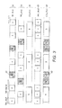
- FIG. 2 is a diagram illustrating a mapping of logical channels to RF frequencies, according to an embodiment of the invention.
- Channels RF 2 22 and RF 3 24 are equipped with one antenna.
- logical channel LNC 1 26 is arranged for carrying data streams with multi-transmitter encoding schemes (M1xO), e.g., MIMO or MISO encoding schemes.
- Logical channels LNC 2 28 and LNC 3 30 are arranged for carrying data streams with single transmitter encoding schemes (SIxO), e.g., Single Input, Multiple Output (SIMO) or SISO encoding schemes.
- SIxO single transmitter encoding schemes
- a first set of data streams such as, for example, PLPs
- a first series of logical frames which are themselves mapped to a first sequence of additional physical slots, such as FEF slots, within several radio frequency channels to form a first logical channel for transmitting the first set of data streams.
- the logical channel may be referred to as a Logical NGH Channel (LNC).
- the first set of data streams may have a multi-transmitter encoding scheme, such as, for example, a MIMO or MISO encoding scheme, but not all of the first set of data streams need have the same multi-transmitter coding scheme.
- At least one of the first set of said plurality of data streams may have a multi-transmitter encoding scheme for a different number of transmit antennas than another of the first set.
- the first series of logical frames are transmitted in the first sequence of additional physical slots using the same pilot pattern for each of the slots in the first sequence of slots and for each of data streams. Sharing the same pilot pattern between data streams having different multi-transmitter coding schemes allows the data streams to be mapped to the same logical channel.
- the first pilot pattern may be selected to be appropriate to a multi-transmitter encoding scheme used by one of the first set of data streams requiring the highest number of pilot tones, so that each of the data streams may operate effectively, for example performing channel estimation, according to its respective multi-transmitter encoding scheme.
- a second set of data streams are mapped onto a second series of logical frames, which are then mapped to a second sequence of additional physical slots, also within several radio frequency channels to form a second logical channel for transmitting the second set of data streams.
- the second series of logical frames are transmitted in the second sequence of additional physical slots, using a different, second, pilot pattern than the pilot pattern used to transmit the first series of logical frames, but using the same second pilot pattern for each of the slots in the second sequence of slots and for each of second set of data streams.
- At least one additional physical slot of the first sequence may be a time slot within a transmission sequence of the same radio frequency channel as at least one additional physical slot of the second sequence. Additional physical slots on the same radio frequency channel may be arranged to use different pilot patterns. This allows two logical channels to use additional physical slots within the transmission sequence of the same radio frequency channel, even if the data streams carried by one logical channel have an encoding scheme using a different pilot pattern than that used by the data streams carried by the other logical channel. This may allow the provision of logical channels without the restriction that the logical channel is limited to being formed from only those radio frequency channels that use the same encoding scheme, for example, the multi-transmitter encoding scheme, as the data stream.
- the first sequence of additional physical slots is selected to be arranged for transmission by a number of antennas at least as great as the maximum number of transmit antennas required by a multi-transmitter encoding scheme used by any of the first set of data streams, so that each of the data streams may operate according to its respective multi-transmitter encoding scheme in each of the additional physical slots used for the logical channel for transmission of the data streams.
- the mapping of the first set of data streams onto the first series of logical frames is arranged so that an integer number of space-time code blocks of a multi-transmitter encoding scheme are mapped to each OFDM symbol, so that space-time code blocks are not broken up, and elements of each code block are kept on the same OFDM symbol. This maintains the effectiveness of the space-time coding, for example, in terms of error rate performance as a function of signal to noise ratio.
- mapping of the first set of data streams onto the first series of logical frames may be arranged so that each OFDM symbol to which the first set of the plurality of data streams is mapped has a number of data subcarriers that is an integer multiple of a minimum common multiple of lengths of space-time code blocks used by the first set of said plurality of data streams. This ensures that an integer number of space-time code blocks of a multi-transmitter encoding scheme may be mapped to each OFDM symbol, so that no space-time code blocks need be split up between OFDM symbols, as doing so may reduce the effectiveness of the coding.
- the mapping of the first set of data streams onto the first series of logical frames may be arranged so that frequency interleaving results in mapping of a given space-time code block of a multi-transmitter encoding scheme to contiguous data subcarriers, so that the effectiveness of the space-time coding, for example in terms of error rate performance as a function of signal to noise ratio, may be maintained.
- the contiguous data subcarriers are contiguous before the insertion of pilot tones; a pilot tone may in principle be inserted between two of the contiguous data subcarriers.
- the second pilot pattern is chosen to be appropriate to an encoding scheme used by at least one of the second set of data streams requiring the highest number of pilot tones, so that the first and second logical channels may each be arranged to use a respective pilot pattern appropriate to the set of data streams carried.
- Each of the second set of the plurality of data streams may be arranged for SISO transmission.
- the pilot pattern used for the second logical channel may be appropriate for SISO transmission, which typically involves a lower number of pilot tones, and so allows a larger number of subcarriers to be allocated for data transmission, increasing the efficiency of the data transmission scheme.
- MIXO Multiple Input, single or multiple Output
- SIXO Single Input, single or multiple Output
- LNC logical channels
- MIXO or SIXO at the slot level. This is motivated by the presence of L1-pre in every slot, and it is the L1-pre that signals the pilot pattern used in the additional physical slot.
- the logical frame which may be a Logical NGH Frame (LNF), which is composed of multiple slots, can have different MIXO or SIXO parts.
- LNF Logical NGH Frame
- the multiplexing of MIXO and SIXO may be performed at the LNC level, so that the pilot pattern may be defined at the LNC level. This may provide efficient multiplexing without affecting the flexibility for allowing some PLPs to be SIXO, since these can be allocated to a SIXO LNC.
- the same pilot pattern applies for MISO and MIMO, and the pilot pattern is determined by the higher number of transmit antennas of the encoding schemes used by the PLPs.
- the P2 symbols may then have different MIMO schemes, since different PLPs (signalling or data) might be carried (fully or partly) in P2 symbol.
- the usage of at least a pair-wise cell interleaver is needed, so that cells are not broken up.
- the pair-wise cell interleaver extends to a more general case where the pairing extends to more than 2 cells.
- a logical channel enables a receiver to receive all the services/PLPs multiplexed on the LNC with a single tuner.
- the service is transmitted over multiple PLPs (e.g., using SVC)
- all the PLPs of that service may be transmitted in the same LNC, since receiving multiple associated PLPs in different LNCs may require more than one tuner.
- the pilot pattern used over the whole LNC is selected to support MIXO.
- the pilot scheme used in the LNC is MIXO
- the multiplexing of SIXO and MIXO in the same LNC may be avoided, since the pilot scheme and pilot pattern used for MIXO may be inefficient when applied to SIXO.
- all NGH slots, that is to say additional physical slots, mapped to a MIXO LNC have the same number of transmitting antennas (Nt).
- the pilot pattern used in the LNC is typically defined in the L1-Pre part of the preamble at the beginning of each NGH slot.
- FIG. 2 illustrates a first example of an allocation of additional physical layer slots on three radio frequency channels to three logical channels (LNCs) 26, 28, 30.
- LNCs logical channels
- a SIXO LNC uses a slot in an RF with two transmitting antennas
- a method of encoding SIXO transmission for transmission from multiple antennas such as eSFN encoding, could be used so that encoding intended for use with a single transmitting antenna may be used for transmission from two antennas, for example, in the case the two antennas must be used (these slots are shaded in FIG. 2 ).
- eSFN is a method of encoding for SIXO when it is not desirable to inhibit transmission from one of the antennas, for example to avoid power fluctuations between transmitting antennas.
- eSFN is transparent to the receiver, and so it is typically not necessary to signal its use.
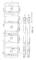
- Two logical channels are shown, LNC 1 38 carries MIXO data streams and LNC 2 40 carries SIXO data streams.
- the shaded slots e.g., slots indicated by reference numeral 42, are for transmission of SIXO using two antennas, so they may be eSFN encoded.
- FIG. 4 illustrates the case of MIMO.
- the logical channel (LNC) and a logical frame (LNF) are applied in similar way to the application for SIXO.
- the start of the LNF and the length of the L1-Post are signalled in the L1-Pre parts of the logical frame.
- the number of data cells in the LNF is typically fixed and signalled in the L1-Post. It can be seen that the logical frame is mapped to Antenna Group 1 44 and Antenna Group 2 46 for transmission.
- FIG. 5 illustrates a flow diagram of a process including slot building 50, serial/parallel conversion and cell mapping 52, T-wise (TW) Frequency Interleaving (FI) 54, pilot insertion 56, and Fast Fourier Transform (FFT) and Guard Interval (GI) and P1 symbol insertion 58, in an embodiment of the present invention.
- TW T-wise
- FI Frequency Interleaving
- FFT Fast Fourier Transform
- GI Guard Interval
- Equation (1) the SF codewords c(l) at the input of the slot builder are given by Equation (1) below.
- Equation (2) For Enhanced Spatial Multiplexing (SM), the SF codewords will take the shape of Equation (2) below.
- a 3xN hybrid scheme may use SF codewords as set forth in Equation (3), Equation (4) and Equation (5) below.
- any MIMO codeword using Space-Frequency block encoding will provide a codeword of size as set forth in Equation (6) below.
- Q is the number of cells encapsulated into the same SF codeword. Any codeword will be of size N t ⁇ T, with N t being the number of transmit antennas and T the number of cells over which the channel should be constant (or as much as possible).
- the spatial rate is obtained as T / Q .
- the pilot pattern is determined by the PLP using the maximum number of transmitting antennas ( N tmax ).
- the cells generated after the XIXO encoding are separated according to its antenna group. This process may be handled by a Serial to Parallel (S/P) process, where each N t consecutive elements/cells are split into different paths.
- S/P Serial to Parallel
- the SF codewords may be extended to be N tmax ⁇ T by inserting rows with zeros during the encoding process.
- the M blocks may be mapped to the respective cells in each slot, one slot being formed by one P2 symbol of C P2 ⁇ N P2 cells, N data data OFDM symbols of C data ⁇ N data cells and a (optional) slot closing symbol of C FC ⁇ 1 cells.
- the mapping of the M blocks may be carried out first in a frequency direction (column-wise) and then in a time direction.
- the number of blocks mapped per OFDM symbol is an integer: C P ⁇ 2 ⁇ C data ⁇ C FC / T max ⁇ Z where z is an integer.
- Each block of T max cells are mapped onto adjacent subcarriers, typically to a contiguous block of data subcarriers, before the insertion of any pilot tones at pilot tone insertion blocks 64a, 64b.
- Space-time code words are kept in contiguous blocks. In FIG. 6 , components of a given code word are identified by the same letter. Following pilot tone insertion 64a, 64b, an FFT is typically performed and a GI is inserted at 66a, 66b.
- the receiver In order to extract the information from received signals regarding L1 Signalling and Data PLP, the receiver needs to know the number of antennas used for transmission as well as the T ma x value used during the T-wise frequency interleaving. These two parameters are typically related, and not all combinations are possible, so that a signalling format may be used, as illustrated in FIG. 7 .
- the upper table of FIG. 7 relates to the case where transmission is by a maximum of two antennas, in which case it can be seen that two bits are needed to signal the information.
- the lower table relates to the case where transmission is by a maximum of three antennas, from which it can be seen that three bits are needed. This case may include hybrid Terrestrial/Satellite transmission (TER/SAT).
- n S3 bits are necessary, these bits can be signalled during the starting P1 symbol (as illustrated in FIG. 1 ), as illustrated in FIG. 8 .
- all bits available for NGH signalling can be combined into a single word of 4+ n S3 bits which can be used to signal all the possible combinations of FFT size, Guard Interval, waveform, number of transmitting antennas, and the T-wise parameter.
- signalling is arranged to indicate to the receiver the type of space-frequency encoding that is used for the different associated PLPs, as illustrated in FIG. 9 .
- P 1 signalling 90 is typically transmitted at the start of a FEF slot.
- the MIMO encoding of the L1-Post is signalled in the L1-Pre, as three bits that may be designated as L1_POST_MIMO.
- the MIMO encoding of each PLP may be signalled in the PLP loop of the L1-Post 94 configurable part, as designated as PLP_MIMO (3 bits) 96.
- Embodiments of the present invention have been described in which mapping of additional physical layer slots to a logical channel depends on the configuration of the logical channel regarding a single input or multiple input encoding scheme.
- a logical channel may use additional physical layer slots having a number of antennas of at least the maximum number of transmitting antennas used in the MIMO encoding.
- a single pilot pattern may be used for the whole logical channel adjusted to the maximum number of transmitting antennas.
- a method of multiplexing PLPs of different MIMO encoding schemes has been described in which each PLP can use a different MIMO encoding, including the L1 signaling.
- a mapping of MIMO codewords to the slots has been described, which allows T-wise frequency interleaving.
- a T-wise frequency interleaving scheme may be based on T2 frequency interleaving sequences.
- An L1 signaling scheme has been described that allows the receiver to detect the MIMO configuration of each logical channel (LNC) and extract the MIXO/SIXO data streams (PLPs).
Landscapes
- Engineering & Computer Science (AREA)
- Signal Processing (AREA)
- Computer Networks & Wireless Communication (AREA)
- Radio Transmission System (AREA)
- Mobile Radio Communication Systems (AREA)
- Time-Division Multiplex Systems (AREA)
Applications Claiming Priority (2)
| Application Number | Priority Date | Filing Date | Title |
|---|---|---|---|
| GB1115833.4A GB2494650B (en) | 2011-09-13 | 2011-09-13 | Additional data streams for multi-transmitter wireless systems |
| KR1020120097839A KR20130029012A (ko) | 2011-09-13 | 2012-09-04 | 무선 시스템에서 데이터 스트림들을 송수신하는 방법 및 장치 |
Publications (2)
| Publication Number | Publication Date |
|---|---|
| EP2571191A2 true EP2571191A2 (fr) | 2013-03-20 |
| EP2571191A3 EP2571191A3 (fr) | 2014-11-26 |
Family
ID=46800126
Family Applications (1)
| Application Number | Title | Priority Date | Filing Date |
|---|---|---|---|
| EP12184110.0A Withdrawn EP2571191A3 (fr) | 2011-09-13 | 2012-09-12 | Appareil et procédé de transmission/réception d'un flux de données dans un système sans fil |
Country Status (3)
| Country | Link |
|---|---|
| US (1) | US10033493B2 (fr) |
| EP (1) | EP2571191A3 (fr) |
| WO (1) | WO2013039323A2 (fr) |
Cited By (1)
| Publication number | Priority date | Publication date | Assignee | Title |
|---|---|---|---|---|
| US20140229803A1 (en) * | 2010-04-01 | 2014-08-14 | Lg Electronics Inc. | Broadcast signal transmitting apparatus, broadcast signal receiving apparatus, and broadcast signal transceiving method in a broadcast signal transceiving apparatus |
Families Citing this family (6)
| Publication number | Priority date | Publication date | Assignee | Title |
|---|---|---|---|---|
| KR102133853B1 (ko) * | 2013-04-21 | 2020-07-14 | 엘지전자 주식회사 | 방송 신호 송신 장치, 방송 신호 수신 장치, 방송 신호 송신 방법 및 방송 신호 수신 방법 |
| KR101801585B1 (ko) * | 2013-08-01 | 2017-11-27 | 엘지전자 주식회사 | 방송 신호 송신 장치, 방송 신호 수신 장치, 방송 신호 송신 방법 및 방송 신호 수신 방법 |
| US12175300B2 (en) | 2021-08-11 | 2024-12-24 | Apple Inc. | Software control techniques for graphics hardware that supports logical slots and reservation of graphics hardware based on a priority threshold |
| US12190164B2 (en) | 2021-08-11 | 2025-01-07 | Apple Inc. | Kickslot manager circuitry for graphics processors |
| US12333339B2 (en) | 2021-08-11 | 2025-06-17 | Apple Inc. | Affinity-based graphics scheduling |
| US12086644B2 (en) * | 2021-08-11 | 2024-09-10 | Apple Inc. | Logical slot to hardware slot mapping for graphics processors |
Citations (1)
| Publication number | Priority date | Publication date | Assignee | Title |
|---|---|---|---|---|
| GB1100901A (en) | 1964-05-27 | 1968-01-24 | British Celanese | Oxidation of ethylene |
Family Cites Families (18)
| Publication number | Priority date | Publication date | Assignee | Title |
|---|---|---|---|---|
| JPS5860846A (ja) | 1981-10-06 | 1983-04-11 | Nec Corp | チヤンネル組合せの誤り検出装置 |
| US7570619B2 (en) * | 2004-02-13 | 2009-08-04 | Broadcom Corporation | Long training sequence method and device for wireless communications |
| JP4824486B2 (ja) | 2006-05-01 | 2011-11-30 | 株式会社エヌ・ティ・ティ・ドコモ | 基地局及び通信方法 |
| JP2008017096A (ja) | 2006-07-05 | 2008-01-24 | Fujitsu Ltd | 複数アンテナによる送信/受信を行う通信システム、その送信装置及び受信装置 |
| KR101520667B1 (ko) * | 2007-09-10 | 2015-05-18 | 엘지전자 주식회사 | 다중 안테나 시스템에서의 파일럿 부반송파 할당 방법 |
| EP2071794B1 (fr) * | 2007-12-12 | 2010-03-24 | Lg Electronics Inc. | Appareil pour la transmission et la réception d'un signal et procédé pour la transmission et la réception d'un signal |
| KR100937430B1 (ko) | 2008-01-25 | 2010-01-18 | 엘지전자 주식회사 | 신호 송수신 방법 및 신호 송수신 장치 |
| US8248910B2 (en) * | 2008-01-29 | 2012-08-21 | Nokia Corporation | Physical layer and data link layer signalling in digital video broadcast preamble symbols |
| KR100937429B1 (ko) | 2008-02-04 | 2010-01-18 | 엘지전자 주식회사 | 신호 송수신 방법 및 신호 송수신 장치 |
| CN104158617A (zh) * | 2008-03-10 | 2014-11-19 | 蔚蓝公司 | 高效及一致的无线下行链路信道配置 |
| JP5353049B2 (ja) | 2008-04-28 | 2013-11-27 | 富士通株式会社 | 無線通信方法、及び無線通信装置 |
| EP2131540B1 (fr) | 2008-06-04 | 2013-09-18 | Sony Corporation | Nouvelle structure de cadre pour systèmes à multiporteuses |
| JP2010041587A (ja) | 2008-08-07 | 2010-02-18 | Sharp Corp | マルチキャリア送信装置、受信装置、通信システム、送信方法、受信方法及びプログラム |
| EP2357745B1 (fr) * | 2010-01-07 | 2015-06-03 | Samsung Electronics Co., Ltd. | Procédé et appareil de services de diffusion dans un système de diffusion vidéo numérique |
| EP3148182B1 (fr) * | 2010-02-08 | 2018-08-15 | LG Electronics Inc. | Appareil de transmission et appareil de réception de signal de diffusion, procédé d'émission-réception d'un signal de diffusion dans un appareil d'émission-réception d'un signal de diffusion |
| US9236927B2 (en) * | 2010-02-25 | 2016-01-12 | Sony Corporation | Transmission apparatus and method for transmission of data in a multi-carrier broadcast system |
| EP2362654A1 (fr) | 2010-02-26 | 2011-08-31 | Panasonic Corporation | En-têtes de trame de bande courte |
| ES2657428T3 (es) | 2011-06-24 | 2018-03-05 | Sun Patent Trust | Dispositivo de transmisión, procedimiento de transmisión, dispositivo de recepción y procedimiento de recepción |
-
2012
- 2012-09-12 EP EP12184110.0A patent/EP2571191A3/fr not_active Withdrawn
- 2012-09-12 WO PCT/KR2012/007316 patent/WO2013039323A2/fr not_active Ceased
- 2012-09-13 US US13/614,061 patent/US10033493B2/en active Active
Patent Citations (1)
| Publication number | Priority date | Publication date | Assignee | Title |
|---|---|---|---|---|
| GB1100901A (en) | 1964-05-27 | 1968-01-24 | British Celanese | Oxidation of ethylene |
Non-Patent Citations (1)
| Title |
|---|
| "802.11 Wireless Networks: The definitive Guide", 30 April 2005, O'REILLY, ISBN: 97805961005210, article MATTHEW GAST: "802.11 Wireless Networks: The definitive Guide", pages: 311 - 342, XP055215530 * |
Cited By (7)
| Publication number | Priority date | Publication date | Assignee | Title |
|---|---|---|---|---|
| US20140229803A1 (en) * | 2010-04-01 | 2014-08-14 | Lg Electronics Inc. | Broadcast signal transmitting apparatus, broadcast signal receiving apparatus, and broadcast signal transceiving method in a broadcast signal transceiving apparatus |
| US9143271B2 (en) | 2010-04-01 | 2015-09-22 | Lg Electronics Inc. | Broadcasting signal transmitting apparatus, broadcast signal receiving apparatus, and broadcast signal transceiving method in a broadcast signal transceiving apparatus |
| US9300435B2 (en) * | 2010-04-01 | 2016-03-29 | Lg Electronics Inc. | Broadcast signal transmitting apparatus, broadcast signal receiving apparatus, and broadcast signal transceiving method in a broadcast signal transceiving apparatus |
| US9432308B2 (en) | 2010-04-01 | 2016-08-30 | Lg Electronics Inc. | Broadcast signal transmitting apparatus, broadcast signal receiving apparatus, and broadcast signal transceiving method in a broadcast signal transceiving apparatus |
| US9490937B2 (en) | 2010-04-01 | 2016-11-08 | Lg Electronics Inc. | Broadcasting signal transmitting apparatus, broadcast signal receiving apparatus, and broadcast signal transceiving method in a broadcast signal transceiving apparatus |
| US10111133B2 (en) | 2010-04-01 | 2018-10-23 | Lg Electronics Inc. | Broadcasting signal transmitting apparatus, broadcast signal receiving apparatus, and broadcast signal transceiving method in a broadcast signal transceiving apparatus |
| US10123234B2 (en) | 2010-04-01 | 2018-11-06 | Lg Electronics Inc. | Broadcast signal transmitting apparatus, broadcast signal receiving apparatus, and broadcast signal transceiving method in a broadcast signal transceiving apparatus |
Also Published As
| Publication number | Publication date |
|---|---|
| US10033493B2 (en) | 2018-07-24 |
| EP2571191A3 (fr) | 2014-11-26 |
| US20130064275A1 (en) | 2013-03-14 |
| WO2013039323A2 (fr) | 2013-03-21 |
| WO2013039323A3 (fr) | 2013-05-10 |
Similar Documents
| Publication | Publication Date | Title |
|---|---|---|
| US11271785B2 (en) | Apparatus and method for sending and receiving broadcast signals | |
| US10999112B2 (en) | Apparatus for transmitting broadcast signals, apparatus for receiving broadcast signals, method for transmitting broadcast signals and method for receiving broadcast signals | |
| US11153049B2 (en) | Apparatus for transmitting broadcast signals, apparatus for receiving broadcast signals, method for transmitting broadcast signals and method for receiving broadcast signals | |
| US9258083B2 (en) | Transmission device, transmission method, reception device, reception method, integrated circuit, and program | |
| US12132945B2 (en) | Apparatus for transmitting broadcast signals, apparatus for receiving broadcast signals, method for transmitting broadcast signals and method for receiving broadcast signals | |
| US9774893B2 (en) | Apparatus for transmitting broadcast signals, apparatus for receiving broadcast signals, method for transmitting broadcast signals and method for receiving broadcast signals | |
| US10715966B2 (en) | Apparatus and method for sending and receiving broadcast signals | |
| US20140247828A1 (en) | Broadcasting signal transmitter/receiver and broadcasting signal transmission/reception method | |
| EP2571191A2 (fr) | Appareil et procédé de transmission/réception d'un flux de données dans un système sans fil | |
| CN107113450A (zh) | 广播信号发送装置、广播信号接收装置、广播信号发送方法以及广播信号接收方法 | |
| CN106575969A (zh) | 用于收发广播信号的装置和方法 | |
| US9438388B2 (en) | Apparatus for transmitting broadcast signals, apparatus for receiving broadcast signals, method for transmitting broadcast signals and method for receiving broadcast signals | |
| CN105940626A (zh) | 用于接收广播信号的方法和设备以及用于发送广播信号的方法和设备 | |
| CN107005522A (zh) | 广播信号发送和接收装置和方法 | |
| WO2015037873A1 (fr) | Dispositif de réception de radiodiffusion et procédé de fonctionnement de ce dernier | |
| AU2012309320B2 (en) | Method and apparatus for transmitting/receiving data stream in wireless system |
Legal Events
| Date | Code | Title | Description |
|---|---|---|---|
| PUAI | Public reference made under article 153(3) epc to a published international application that has entered the european phase |
Free format text: ORIGINAL CODE: 0009012 |
|
| AK | Designated contracting states |
Kind code of ref document: A2 Designated state(s): AL AT BE BG CH CY CZ DE DK EE ES FI FR GB GR HR HU IE IS IT LI LT LU LV MC MK MT NL NO PL PT RO RS SE SI SK SM TR |
|
| AX | Request for extension of the european patent |
Extension state: BA ME |
|
| PUAL | Search report despatched |
Free format text: ORIGINAL CODE: 0009013 |
|
| AK | Designated contracting states |
Kind code of ref document: A3 Designated state(s): AL AT BE BG CH CY CZ DE DK EE ES FI FR GB GR HR HU IE IS IT LI LT LU LV MC MK MT NL NO PL PT RO RS SE SI SK SM TR |
|
| AX | Request for extension of the european patent |
Extension state: BA ME |
|
| RIC1 | Information provided on ipc code assigned before grant |
Ipc: H04W 72/00 20090101ALI20141021BHEP Ipc: H04L 5/00 20060101AFI20141021BHEP |
|
| 17P | Request for examination filed |
Effective date: 20150521 |
|
| RBV | Designated contracting states (corrected) |
Designated state(s): AL AT BE BG CH CY CZ DE DK EE ES FI FR GB GR HR HU IE IS IT LI LT LU LV MC MK MT NL NO PL PT RO RS SE SI SK SM TR |
|
| 17Q | First examination report despatched |
Effective date: 20150929 |
|
| STAA | Information on the status of an ep patent application or granted ep patent |
Free format text: STATUS: THE APPLICATION IS DEEMED TO BE WITHDRAWN |
|
| 18D | Application deemed to be withdrawn |
Effective date: 20180404 |