EP2571337A1 - Procédé de production d'une cavité d'accélérateur supraconducteur - Google Patents
Procédé de production d'une cavité d'accélérateur supraconducteur Download PDFInfo
- Publication number
- EP2571337A1 EP2571337A1 EP11780581A EP11780581A EP2571337A1 EP 2571337 A1 EP2571337 A1 EP 2571337A1 EP 11780581 A EP11780581 A EP 11780581A EP 11780581 A EP11780581 A EP 11780581A EP 2571337 A1 EP2571337 A1 EP 2571337A1
- Authority
- EP
- European Patent Office
- Prior art keywords
- portions
- ring
- welding
- joined
- axial direction
- Prior art date
- Legal status (The legal status is an assumption and is not a legal conclusion. Google has not performed a legal analysis and makes no representation as to the accuracy of the status listed.)
- Granted
Links
Images


Classifications
-
- H—ELECTRICITY
- H05—ELECTRIC TECHNIQUES NOT OTHERWISE PROVIDED FOR
- H05H—PLASMA TECHNIQUE; PRODUCTION OF ACCELERATED ELECTRICALLY-CHARGED PARTICLES OR OF NEUTRONS; PRODUCTION OR ACCELERATION OF NEUTRAL MOLECULAR OR ATOMIC BEAMS
- H05H7/00—Details of devices of the types covered by groups H05H9/00, H05H11/00, H05H13/00
- H05H7/14—Vacuum chambers
- H05H7/18—Cavities; Resonators
- H05H7/20—Cavities; Resonators with superconductive walls
-
- B—PERFORMING OPERATIONS; TRANSPORTING
- B23—MACHINE TOOLS; METAL-WORKING NOT OTHERWISE PROVIDED FOR
- B23K—SOLDERING OR UNSOLDERING; WELDING; CLADDING OR PLATING BY SOLDERING OR WELDING; CUTTING BY APPLYING HEAT LOCALLY, e.g. FLAME CUTTING; WORKING BY LASER BEAM
- B23K15/00—Electron-beam welding or cutting
- B23K15/04—Electron-beam welding or cutting for welding annular seams
-
- B—PERFORMING OPERATIONS; TRANSPORTING
- B23—MACHINE TOOLS; METAL-WORKING NOT OTHERWISE PROVIDED FOR
- B23K—SOLDERING OR UNSOLDERING; WELDING; CLADDING OR PLATING BY SOLDERING OR WELDING; CUTTING BY APPLYING HEAT LOCALLY, e.g. FLAME CUTTING; WORKING BY LASER BEAM
- B23K26/00—Working by laser beam, e.g. welding, cutting or boring
- B23K26/12—Working by laser beam, e.g. welding, cutting or boring in a special environment or atmosphere, e.g. in an enclosure
- B23K26/122—Working by laser beam, e.g. welding, cutting or boring in a special environment or atmosphere, e.g. in an enclosure in a liquid, e.g. underwater
-
- B—PERFORMING OPERATIONS; TRANSPORTING
- B23—MACHINE TOOLS; METAL-WORKING NOT OTHERWISE PROVIDED FOR
- B23K—SOLDERING OR UNSOLDERING; WELDING; CLADDING OR PLATING BY SOLDERING OR WELDING; CUTTING BY APPLYING HEAT LOCALLY, e.g. FLAME CUTTING; WORKING BY LASER BEAM
- B23K26/00—Working by laser beam, e.g. welding, cutting or boring
- B23K26/12—Working by laser beam, e.g. welding, cutting or boring in a special environment or atmosphere, e.g. in an enclosure
- B23K26/1224—Working by laser beam, e.g. welding, cutting or boring in a special environment or atmosphere, e.g. in an enclosure in vacuum
-
- B—PERFORMING OPERATIONS; TRANSPORTING
- B23—MACHINE TOOLS; METAL-WORKING NOT OTHERWISE PROVIDED FOR
- B23K—SOLDERING OR UNSOLDERING; WELDING; CLADDING OR PLATING BY SOLDERING OR WELDING; CUTTING BY APPLYING HEAT LOCALLY, e.g. FLAME CUTTING; WORKING BY LASER BEAM
- B23K26/00—Working by laser beam, e.g. welding, cutting or boring
- B23K26/20—Bonding
- B23K26/206—Laser sealing
-
- B—PERFORMING OPERATIONS; TRANSPORTING
- B23—MACHINE TOOLS; METAL-WORKING NOT OTHERWISE PROVIDED FOR
- B23K—SOLDERING OR UNSOLDERING; WELDING; CLADDING OR PLATING BY SOLDERING OR WELDING; CUTTING BY APPLYING HEAT LOCALLY, e.g. FLAME CUTTING; WORKING BY LASER BEAM
- B23K26/00—Working by laser beam, e.g. welding, cutting or boring
- B23K26/20—Bonding
- B23K26/21—Bonding by welding
- B23K26/24—Seam welding
- B23K26/28—Seam welding of curved planar seams
-
- B—PERFORMING OPERATIONS; TRANSPORTING
- B23—MACHINE TOOLS; METAL-WORKING NOT OTHERWISE PROVIDED FOR
- B23K—SOLDERING OR UNSOLDERING; WELDING; CLADDING OR PLATING BY SOLDERING OR WELDING; CUTTING BY APPLYING HEAT LOCALLY, e.g. FLAME CUTTING; WORKING BY LASER BEAM
- B23K33/00—Specially-profiled edge portions of workpieces for making soldering or welding connections; Filling the seams formed thereby
-
- B—PERFORMING OPERATIONS; TRANSPORTING
- B23—MACHINE TOOLS; METAL-WORKING NOT OTHERWISE PROVIDED FOR
- B23K—SOLDERING OR UNSOLDERING; WELDING; CLADDING OR PLATING BY SOLDERING OR WELDING; CUTTING BY APPLYING HEAT LOCALLY, e.g. FLAME CUTTING; WORKING BY LASER BEAM
- B23K2101/00—Articles made by soldering, welding or cutting
- B23K2101/04—Tubular or hollow articles
-
- Y—GENERAL TAGGING OF NEW TECHNOLOGICAL DEVELOPMENTS; GENERAL TAGGING OF CROSS-SECTIONAL TECHNOLOGIES SPANNING OVER SEVERAL SECTIONS OF THE IPC; TECHNICAL SUBJECTS COVERED BY FORMER USPC CROSS-REFERENCE ART COLLECTIONS [XRACs] AND DIGESTS
- Y10—TECHNICAL SUBJECTS COVERED BY FORMER USPC
- Y10T—TECHNICAL SUBJECTS COVERED BY FORMER US CLASSIFICATION
- Y10T29/00—Metal working
- Y10T29/49—Method of mechanical manufacture
- Y10T29/49002—Electrical device making
- Y10T29/49014—Superconductor
Definitions
- the present invention relates to a method of manufacturing a superconducting accelerator cavity.
- a superconducting accelerator cavity accelerates elementary particles that pass through the interior thereof, the characteristics of the inner surfaces thereof are important in order for a superconducting accelerator cavity to achieve a certain level of performance.
- a superconducting accelerator cavity is formed by joining a plurality of ring-shaped members, such as cells, beam pipes, and so forth, which are placed one after another in an axial direction (see Patent Literature 1 and Patent Literature 2). This joining is conventionally performed from outside by means of penetration welding in the form of electron beam welding or laser welding in a vacuum atmosphere because a vacuum atmosphere has low contamination caused by impurities.
- the welding work is typically performed by placing the plurality of ring-shaped members one after another in the axial direction so as to be horizontally oriented and by joining them so that joints are oriented in a vertical direction.
- weld beads can be made substantially uniform on both sides of the joints, thus making it possible to form relatively smooth weld beads.
- the plurality of ring-shaped members When the plurality of ring-shaped members are placed one after another in the axial direction so as to be horizontally oriented, because a center portion thereof tends to move downward due to gravity, a defective product may result due to deformation.
- the plurality of ring-shaped members are supported by large, strong jigs in order to suppress this deformation caused by the weight, and this presents a problem in that the size of a welding apparatus increases, which also makes placement of the ring-shaped members complicated and time consuming.
- the present invention has been conceived in light of the above-described circumstances, and an object thereof is to provide a method of manufacturing a superconducting accelerator cavity with which a support structure at the time of welding can be simplified and which also makes inner surfaces of a product smooth.
- An aspect of the present invention is a method of manufacturing a superconducting accelerator cavity in which a plurality of ring-shaped bodies having opening portions at both ends thereof in an axial direction are placed one after another in the axial direction, contact portions where corresponding opening portions come into contact with each other are joined by welding, and thus, a superconducting accelerator cavity is manufactured, wherein the ring-shaped bodies to be joined are arranged so that the axial direction thereof extends in a vertical direction; and concave portions that are concave towards an outer side are also formed at inner circumferential surfaces located below the contact portions of the ring-shaped bodies positioned at a bottom; and wherein the contact portions are joined from outside by means of penetration welding.
- the ring-shaped bodies to be joined are arranged so that the axial direction extends in the vertical direction.
- the contact portions where the corresponding opening portions come in contact with each other are positioned so as to extend substantially in the horizontal direction.
- the ring-shaped bodies are joined with each other by applying penetration welding from outside of the contact portions formed in this way. Because the ring-shaped bodies to be joined are arranged in this way so that the axial direction thereof extends in the vertical direction, positional shifting of the contact portions due to gravity can be sufficiently suppressed by the ring-shaped bodies themselves. Therefore, because it is possible to simplify a structure for holding the plurality of ring-shaped members, the size of the welding apparatus can be reduced, and the work involved in placing the ring-shaped members can also be performed easily and in a short period of time.
- the concave portions that are concave towards the outer side are formed at the inner circumferential surfaces located below the contact portions of the ring-shaped bodies positioned on the bottom side, the molten drops that hang downward due to gravity flow into the concave portions. Because the molten drops do not protrude inward if the molten drops that hang downward flow into the concave portions in this way, in other words, if they fill the concave portions, the weld beads formed on the inner circumferential surfaces of the ring-shaped bodies can be made smooth.
- the amount of molten drops that occur at the bottom-side ring-shaped bodies (volume of the bottom-side ring-shaped bodies) is reduced or, conversely, the amount of molten drops that occur at the top-side ring-shaped bodies (volume of the top-side ring-shaped bodies) is increased.
- the weld beads are made smooth in this way, the time required for post-processing can be reduced.
- the concave portions may be formed so that a depth thereof decreases toward the bottom side.
- the ring-shaped bodies to be joined are arranged so that the axial direction extends in the vertical direction, the size of the welding apparatus can be reduced, and the work involved in placing the ring-shaped members can also be performed easily and in a short period of time.
- concave portions that are concave towards the outer side are formed at inner circumferential surfaces located below the contact portions of the ring-shaped bodies positioned at the bottom, weld beads formed at the inner circumferential surfaces of the ring-shaped bodies can be made smooth.
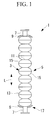
- Fig. 1 is a cross-sectional view of a superconducting accelerator cavity manufactured with a method of manufacturing a superconducting accelerator cavity according to the embodiment of the present invention.
- a superconducting accelerator cavity 1 is provided with a cavity portion 5, in which, for example, nine hollow cylindrical cells (ring-shaped bodies) 3 with swollen center portions are combined by being joined by means of welding, and a pair of hollow cylindrical beam pipes (ring-shaped bodies) 7 that are attached at both ends of the cavity portion 5.
- End plates 9 that form two ends of a jacket, which is a container formed so as to surround the cavity portion 5, are attached to outer circumferential surfaces of the individual beam pipes 7 at the cavity portion 5 sides thereof. Although illustrations thereof are omitted, the beam pipes 7 are provided with input ports to which input couplers are attached, higher order mode couplers that release higher order modes, which inhibit acceleration of beams excited in the cavity portion 5, outside the cavity portion 5, and so forth.
- Iris portions 11, which are the narrowest portions formed between cells 3, are formed in the cavity portion 5.
- the cells 3 have the most-swollen portions at center portions thereof in the axial direction L. These most-swollen portions will be referred to as equator portions 13.
- the cells 3 are formed of half cells (ring-shaped bodies) 15 that are divided in two in the axial direction L with the equator portions 13 serving as boundaries therebetween. The two ends of the half cells 15 form the iris portions (opening portions) 11 and the equator portions (opening portions) 13.
- the half cells 15 and the beam pipes 7 are formed of a superconducting material, for example, a niobium-based material.
- the beam pipes 7, the end plates 9, and the half cells 15 are manufactured as individual constituent members.
- two end parts (ring-shaped bodies) 17 formed of the beam pipes 7, the end plates 9, and the half cells 15 are manufactured.
- the end parts 17 are formed by joining inner circumferential portions of the end plates 9 with the outer circumferential sides at one end of the beam pipes by means of welding and by joining the iris portions 11 of the half cells 15 with inner circumferential sides thereof by means of welding.
- the two end parts 17 and a plurality of half cells 15 are joined by means of welding with a welding apparatus.
- one end part 17 is placed in the welding apparatus so that the axial direction L thereof extends in the vertical direction and so that the half cell 15 therefor is positioned above.
- the plurality of half cells 15 are placed one after another in the axial direction L so that the equator portions 13 are overlaid on each other or so that the iris portions 11 are overlaid on each other, and the other end part 17 is stacked on top of them.
- the half cells 15 of the end parts 17 and the plurality of half cells 15 to be joined by means of welding are arranged so that the axial direction thereof extends in the vertical direction, corresponding contact portions 21 between them extend substantially in the horizontal direction.
- the contact portions 21 extend horizontally, because position shifting of the contact portions 21 due to gravity can be sufficiently suppressed by the half cells 15 themselves, etc., it is possible to simplify the structure for holding the half cells 15 and so forth. Accordingly, the size of the welding apparatus can be reduced and the work involved in placing the half cells 15, etc. can also be performed easily and in a short period of time.
- two half cells 15 form the contact portion 21 by being overlaid on each other at the equator portions 13.
- Recessed-butt-joint processing is applied to end surfaces of the two half cells 15 so that their positions do not shift in the horizontal direction when they are stacked.
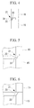
- a straight chamfer 23 is formed at an inner-circumferential-side end surface of the half cell 15 positioned at the bottom.
- the concave portion 25 is formed so that the depth in the horizontal direction decreases toward the bottom side thereof.
- the chamfer 23 that forms the concave portion 25 is formed in a straight line in this embodiment, it is not limited thereto, and it may be curvilinear; in addition, the concave portion 25 may be formed with a curvilinear notch that protrudes outward, as shown in Fig. 5 .
- the recessed-butt-joint processing is applied to the end surfaces of two half cells 15 in this embodiment, it is not limited thereto, and they may be flat surfaces, as shown in Fig. 6 .
- the contact portions 21 configured in this way are irradiated so as to be penetrated from outside with, for example, beams 27, thus performing electron beam welding of the contact portions 21.
- the welding method is not limited to electron beam welding, and it may be laser welding.
- molten drops are formed due to heating by the beams 27. Because the molten drops have liquid properties, they move easily and move downward due to gravity. As shown in Fig. 7 , with the contact portions 21 that are simply abutted, as has conventionally been done, the molten drops hang along the inner surfaces of the half cells 15, thus forming weld beads 31 that protrude more toward the bottom side of the inner circumferential surfaces of the half cells 15.
- the concave portions 25 are formed in this embodiment, for example, as shown in Fig. 4 , the molten drops that hang downward due to gravity flow into the concave portions 25. Because the molten drops do not protrude inward if the molten drops that hang downward flow into the concave portions 25 in this way, in other words, if they fill the concave portions 25, the weld beads 31 formed at the inner circumferential surfaces of the half cells 15 can be made smooth.
- the amount of molten drops that occur at the bottom-side half cells 15 (volume of the bottom-side half cells 15 that melt) is reduced or, conversely, the amount of molten drops that occur at the top-side half cells 15 (volume of the top-side half cells that melt) is increased.
- the weld beads 31 are made smooth in this way, the time required for post-processing can be reduced.
- dumbbells may be formed as ring-shaped bodies in which two half cells 15 are welded so that the corresponding iris portions 11 are overlaid on each other, and these dumbbells may be joined with each other.
- dumbbells formed by processing pipe members may be joined with each other.
- the cavity portion 5 may be integrally formed in portions or as a whole to form a ring-shaped body.
Landscapes
- Engineering & Computer Science (AREA)
- Physics & Mathematics (AREA)
- Optics & Photonics (AREA)
- Mechanical Engineering (AREA)
- Plasma & Fusion (AREA)
- Spectroscopy & Molecular Physics (AREA)
- Particle Accelerators (AREA)
- Welding Or Cutting Using Electron Beams (AREA)
- Laser Beam Processing (AREA)
Applications Claiming Priority (2)
| Application Number | Priority Date | Filing Date | Title |
|---|---|---|---|
| JP2010110145A JP5595114B2 (ja) | 2010-05-12 | 2010-05-12 | 超伝導加速空洞の製造方法 |
| PCT/JP2011/060672 WO2011142324A1 (fr) | 2010-05-12 | 2011-05-09 | Procédé de production d'une cavité d'accélérateur supraconducteur |
Publications (3)
| Publication Number | Publication Date |
|---|---|
| EP2571337A1 true EP2571337A1 (fr) | 2013-03-20 |
| EP2571337A4 EP2571337A4 (fr) | 2013-10-23 |
| EP2571337B1 EP2571337B1 (fr) | 2016-12-28 |
Family
ID=44914380
Family Applications (1)
| Application Number | Title | Priority Date | Filing Date |
|---|---|---|---|
| EP11780581.2A Not-in-force EP2571337B1 (fr) | 2010-05-12 | 2011-05-09 | Procédé de production d'une cavité d'accélérateur supraconducteur |
Country Status (4)
| Country | Link |
|---|---|
| US (1) | US8951936B2 (fr) |
| EP (1) | EP2571337B1 (fr) |
| JP (1) | JP5595114B2 (fr) |
| WO (1) | WO2011142324A1 (fr) |
Cited By (2)
| Publication number | Priority date | Publication date | Assignee | Title |
|---|---|---|---|---|
| CN103619119A (zh) * | 2013-11-18 | 2014-03-05 | 中国科学院近代物理研究所 | 一种超导腔的制备方法 |
| FR3085607A1 (fr) * | 2019-05-21 | 2020-03-13 | Techmeta Engineering Sas | Appareil à souder par faisceau d'électrons |
Families Citing this family (5)
| Publication number | Priority date | Publication date | Assignee | Title |
|---|---|---|---|---|
| JP5804840B2 (ja) * | 2011-08-11 | 2015-11-04 | 三菱重工業株式会社 | 加工装置及び加工方法 |
| JP5985011B1 (ja) * | 2015-06-30 | 2016-09-06 | 三菱重工メカトロシステムズ株式会社 | 超伝導加速器 |
| US10847860B2 (en) * | 2018-05-18 | 2020-11-24 | Ii-Vi Delaware, Inc. | Superconducting resonating cavity and method of production thereof |
| US10856402B2 (en) * | 2018-05-18 | 2020-12-01 | Ii-Vi Delaware, Inc. | Superconducting resonating cavity with laser welded seam and method of formation thereof |
| CN116690024A (zh) * | 2023-06-15 | 2023-09-05 | 淮南新能源研究中心 | 一种超导腔结构及焊接工艺方法 |
Family Cites Families (9)
| Publication number | Priority date | Publication date | Assignee | Title |
|---|---|---|---|---|
| JPS51151237A (en) * | 1975-06-20 | 1976-12-25 | Babcock Hitachi Kk | Method of electron beam welding |
| US5239157A (en) * | 1990-10-31 | 1993-08-24 | The Furukawa Electric Co., Ltd. | Superconducting accelerating tube and a method for manufacturing the same |
| JPH04322100A (ja) * | 1991-04-19 | 1992-11-12 | Furukawa Electric Co Ltd:The | 加速管の製造方法 |
| JP3416249B2 (ja) | 1994-03-07 | 2003-06-16 | 三菱重工業株式会社 | 超伝導加速器 |
| JP3426828B2 (ja) | 1995-12-27 | 2003-07-14 | 修一 野口 | 超伝導加速空洞 |
| JP3959198B2 (ja) * | 1999-03-09 | 2007-08-15 | 株式会社東芝 | 超電導キャビティ、その製造方法、及び超電導加速器 |
| JP2000348900A (ja) * | 1999-06-07 | 2000-12-15 | Toshiba Corp | 超電導高周波加速空胴の製造方法 |
| JP4358764B2 (ja) * | 2005-02-25 | 2009-11-04 | 三菱重工業株式会社 | 超伝導加速空洞 |
| JP4444222B2 (ja) * | 2005-04-12 | 2010-03-31 | 三菱重工業株式会社 | 超伝導加速空洞の製造方法 |
-
2010
- 2010-05-12 JP JP2010110145A patent/JP5595114B2/ja active Active
-
2011
- 2011-05-09 EP EP11780581.2A patent/EP2571337B1/fr not_active Not-in-force
- 2011-05-09 US US13/636,166 patent/US8951936B2/en not_active Expired - Fee Related
- 2011-05-09 WO PCT/JP2011/060672 patent/WO2011142324A1/fr not_active Ceased
Cited By (3)
| Publication number | Priority date | Publication date | Assignee | Title |
|---|---|---|---|---|
| CN103619119A (zh) * | 2013-11-18 | 2014-03-05 | 中国科学院近代物理研究所 | 一种超导腔的制备方法 |
| FR3085607A1 (fr) * | 2019-05-21 | 2020-03-13 | Techmeta Engineering Sas | Appareil à souder par faisceau d'électrons |
| WO2020234334A1 (fr) * | 2019-05-21 | 2020-11-26 | Techmeta Engineering Sas | Appareil a souder par faisceau d'electrons |
Also Published As
| Publication number | Publication date |
|---|---|
| EP2571337A4 (fr) | 2013-10-23 |
| JP5595114B2 (ja) | 2014-09-24 |
| WO2011142324A1 (fr) | 2011-11-17 |
| JP2011238517A (ja) | 2011-11-24 |
| US20130012397A1 (en) | 2013-01-10 |
| US8951936B2 (en) | 2015-02-10 |
| EP2571337B1 (fr) | 2016-12-28 |
Similar Documents
| Publication | Publication Date | Title |
|---|---|---|
| EP2571337B1 (fr) | Procédé de production d'une cavité d'accélérateur supraconducteur | |
| US8630689B2 (en) | Superconducting accelerator cavity and method of manufacturing superconducting accelerator cavity | |
| CN102652047A (zh) | 焊接构造以及焊接方法 | |
| CN102500905B (zh) | 封闭薄壁铝合金框的电子束焊接方法 | |
| WO2015114445A2 (fr) | Procédé de soudage et structure de soudage | |
| KR101256970B1 (ko) | 심레스 파이프 제조장치 및 제조방법 | |
| JP2015512020A (ja) | 注液管レスの均温装置の製造方法およびこの製造方法により製造された均温装置 | |
| KR20200083898A (ko) | 플레이트 열 교환기 | |
| US12288888B2 (en) | Battery module | |
| US20120205351A1 (en) | Stainless steel joining method | |
| US20140112709A1 (en) | Dissimilar material joint, structure in which dissimilar material joint is used, and method of producing the same | |
| JP6981745B2 (ja) | 溶接方法及び溶接構造体 | |
| US8957348B2 (en) | Welding equipment | |
| JP6162397B2 (ja) | 差厚材及びそれを用いた筒状部材 | |
| US20160090845A1 (en) | Dual wall components for gas turbine engines | |
| JP5989860B2 (ja) | 真空容器の製造方法 | |
| CN104603295A (zh) | 用于熔炉的冷却元件 | |
| KR20130097990A (ko) | 이차전지 극주탭 t형상 용접 방법 | |
| JP2013017032A (ja) | 真空容器の製造方法 | |
| JP2017035736A (ja) | Hip用カプセルの製造方法及び焼結体の製造方法 | |
| JP6311511B2 (ja) | ガラス接合体の製造方法 | |
| CN102990219B (zh) | 一种Ti2AlNb合金材料的燃烧室结构件的扩散焊工艺方法 | |
| JP2018001262A (ja) | 管台の溶接方法、管台の検査方法及び管台の製造方法 | |
| KR101428218B1 (ko) | 캐스크 바스켓을 제조하는 방법 | |
| JP6052592B2 (ja) | Hip用カプセルの製造方法 |
Legal Events
| Date | Code | Title | Description |
|---|---|---|---|
| PUAI | Public reference made under article 153(3) epc to a published international application that has entered the european phase |
Free format text: ORIGINAL CODE: 0009012 |
|
| 17P | Request for examination filed |
Effective date: 20120918 |
|
| AK | Designated contracting states |
Kind code of ref document: A1 Designated state(s): AL AT BE BG CH CY CZ DE DK EE ES FI FR GB GR HR HU IE IS IT LI LT LU LV MC MK MT NL NO PL PT RO RS SE SI SK SM TR |
|
| DAX | Request for extension of the european patent (deleted) | ||
| A4 | Supplementary search report drawn up and despatched |
Effective date: 20130924 |
|
| RIC1 | Information provided on ipc code assigned before grant |
Ipc: B23K 26/20 20060101ALI20130918BHEP Ipc: H05H 7/20 20060101AFI20130918BHEP Ipc: B23K 33/00 20060101ALI20130918BHEP Ipc: B23K 15/00 20060101ALI20130918BHEP |
|
| RAP1 | Party data changed (applicant data changed or rights of an application transferred) |
Owner name: MITSUBISHI HEAVY INDUSTRIES MECHATRONICS SYSTEMS, |
|
| GRAP | Despatch of communication of intention to grant a patent |
Free format text: ORIGINAL CODE: EPIDOSNIGR1 |
|
| INTG | Intention to grant announced |
Effective date: 20160715 |
|
| INTG | Intention to grant announced |
Effective date: 20160720 |
|
| GRAS | Grant fee paid |
Free format text: ORIGINAL CODE: EPIDOSNIGR3 |
|
| GRAA | (expected) grant |
Free format text: ORIGINAL CODE: 0009210 |
|
| AK | Designated contracting states |
Kind code of ref document: B1 Designated state(s): AL AT BE BG CH CY CZ DE DK EE ES FI FR GB GR HR HU IE IS IT LI LT LU LV MC MK MT NL NO PL PT RO RS SE SI SK SM TR |
|
| REG | Reference to a national code |
Ref country code: GB Ref legal event code: FG4D |
|
| REG | Reference to a national code |
Ref country code: CH Ref legal event code: EP |
|
| REG | Reference to a national code |
Ref country code: AT Ref legal event code: REF Ref document number: 858271 Country of ref document: AT Kind code of ref document: T Effective date: 20170115 |
|
| REG | Reference to a national code |
Ref country code: IE Ref legal event code: FG4D |
|
| REG | Reference to a national code |
Ref country code: DE Ref legal event code: R096 Ref document number: 602011033878 Country of ref document: DE |
|
| PG25 | Lapsed in a contracting state [announced via postgrant information from national office to epo] |
Ref country code: LV Free format text: LAPSE BECAUSE OF FAILURE TO SUBMIT A TRANSLATION OF THE DESCRIPTION OR TO PAY THE FEE WITHIN THE PRESCRIBED TIME-LIMIT Effective date: 20161228 |
|
| REG | Reference to a national code |
Ref country code: LT Ref legal event code: MG4D |
|
| PG25 | Lapsed in a contracting state [announced via postgrant information from national office to epo] |
Ref country code: LT Free format text: LAPSE BECAUSE OF FAILURE TO SUBMIT A TRANSLATION OF THE DESCRIPTION OR TO PAY THE FEE WITHIN THE PRESCRIBED TIME-LIMIT Effective date: 20161228 Ref country code: NO Free format text: LAPSE BECAUSE OF FAILURE TO SUBMIT A TRANSLATION OF THE DESCRIPTION OR TO PAY THE FEE WITHIN THE PRESCRIBED TIME-LIMIT Effective date: 20170328 Ref country code: SE Free format text: LAPSE BECAUSE OF FAILURE TO SUBMIT A TRANSLATION OF THE DESCRIPTION OR TO PAY THE FEE WITHIN THE PRESCRIBED TIME-LIMIT Effective date: 20161228 Ref country code: GR Free format text: LAPSE BECAUSE OF FAILURE TO SUBMIT A TRANSLATION OF THE DESCRIPTION OR TO PAY THE FEE WITHIN THE PRESCRIBED TIME-LIMIT Effective date: 20170329 |
|
| REG | Reference to a national code |
Ref country code: NL Ref legal event code: MP Effective date: 20161228 |
|
| REG | Reference to a national code |
Ref country code: AT Ref legal event code: MK05 Ref document number: 858271 Country of ref document: AT Kind code of ref document: T Effective date: 20161228 |
|
| PG25 | Lapsed in a contracting state [announced via postgrant information from national office to epo] |
Ref country code: HR Free format text: LAPSE BECAUSE OF FAILURE TO SUBMIT A TRANSLATION OF THE DESCRIPTION OR TO PAY THE FEE WITHIN THE PRESCRIBED TIME-LIMIT Effective date: 20161228 Ref country code: FI Free format text: LAPSE BECAUSE OF FAILURE TO SUBMIT A TRANSLATION OF THE DESCRIPTION OR TO PAY THE FEE WITHIN THE PRESCRIBED TIME-LIMIT Effective date: 20161228 Ref country code: RS Free format text: LAPSE BECAUSE OF FAILURE TO SUBMIT A TRANSLATION OF THE DESCRIPTION OR TO PAY THE FEE WITHIN THE PRESCRIBED TIME-LIMIT Effective date: 20161228 |
|
| PG25 | Lapsed in a contracting state [announced via postgrant information from national office to epo] |
Ref country code: NL Free format text: LAPSE BECAUSE OF FAILURE TO SUBMIT A TRANSLATION OF THE DESCRIPTION OR TO PAY THE FEE WITHIN THE PRESCRIBED TIME-LIMIT Effective date: 20161228 |
|
| PG25 | Lapsed in a contracting state [announced via postgrant information from national office to epo] |
Ref country code: EE Free format text: LAPSE BECAUSE OF FAILURE TO SUBMIT A TRANSLATION OF THE DESCRIPTION OR TO PAY THE FEE WITHIN THE PRESCRIBED TIME-LIMIT Effective date: 20161228 Ref country code: RO Free format text: LAPSE BECAUSE OF FAILURE TO SUBMIT A TRANSLATION OF THE DESCRIPTION OR TO PAY THE FEE WITHIN THE PRESCRIBED TIME-LIMIT Effective date: 20161228 Ref country code: SK Free format text: LAPSE BECAUSE OF FAILURE TO SUBMIT A TRANSLATION OF THE DESCRIPTION OR TO PAY THE FEE WITHIN THE PRESCRIBED TIME-LIMIT Effective date: 20161228 Ref country code: IS Free format text: LAPSE BECAUSE OF FAILURE TO SUBMIT A TRANSLATION OF THE DESCRIPTION OR TO PAY THE FEE WITHIN THE PRESCRIBED TIME-LIMIT Effective date: 20170428 Ref country code: CZ Free format text: LAPSE BECAUSE OF FAILURE TO SUBMIT A TRANSLATION OF THE DESCRIPTION OR TO PAY THE FEE WITHIN THE PRESCRIBED TIME-LIMIT Effective date: 20161228 |
|
| PG25 | Lapsed in a contracting state [announced via postgrant information from national office to epo] |
Ref country code: LU Free format text: LAPSE BECAUSE OF NON-PAYMENT OF DUE FEES Effective date: 20170531 Ref country code: SM Free format text: LAPSE BECAUSE OF FAILURE TO SUBMIT A TRANSLATION OF THE DESCRIPTION OR TO PAY THE FEE WITHIN THE PRESCRIBED TIME-LIMIT Effective date: 20161228 Ref country code: AT Free format text: LAPSE BECAUSE OF FAILURE TO SUBMIT A TRANSLATION OF THE DESCRIPTION OR TO PAY THE FEE WITHIN THE PRESCRIBED TIME-LIMIT Effective date: 20161228 Ref country code: BE Free format text: LAPSE BECAUSE OF FAILURE TO SUBMIT A TRANSLATION OF THE DESCRIPTION OR TO PAY THE FEE WITHIN THE PRESCRIBED TIME-LIMIT Effective date: 20161228 Ref country code: PT Free format text: LAPSE BECAUSE OF FAILURE TO SUBMIT A TRANSLATION OF THE DESCRIPTION OR TO PAY THE FEE WITHIN THE PRESCRIBED TIME-LIMIT Effective date: 20170428 Ref country code: PL Free format text: LAPSE BECAUSE OF FAILURE TO SUBMIT A TRANSLATION OF THE DESCRIPTION OR TO PAY THE FEE WITHIN THE PRESCRIBED TIME-LIMIT Effective date: 20161228 Ref country code: BG Free format text: LAPSE BECAUSE OF FAILURE TO SUBMIT A TRANSLATION OF THE DESCRIPTION OR TO PAY THE FEE WITHIN THE PRESCRIBED TIME-LIMIT Effective date: 20170328 Ref country code: ES Free format text: LAPSE BECAUSE OF FAILURE TO SUBMIT A TRANSLATION OF THE DESCRIPTION OR TO PAY THE FEE WITHIN THE PRESCRIBED TIME-LIMIT Effective date: 20161228 |
|
| REG | Reference to a national code |
Ref country code: DE Ref legal event code: R097 Ref document number: 602011033878 Country of ref document: DE |
|
| PLBE | No opposition filed within time limit |
Free format text: ORIGINAL CODE: 0009261 |
|
| STAA | Information on the status of an ep patent application or granted ep patent |
Free format text: STATUS: NO OPPOSITION FILED WITHIN TIME LIMIT |
|
| PG25 | Lapsed in a contracting state [announced via postgrant information from national office to epo] |
Ref country code: DK Free format text: LAPSE BECAUSE OF FAILURE TO SUBMIT A TRANSLATION OF THE DESCRIPTION OR TO PAY THE FEE WITHIN THE PRESCRIBED TIME-LIMIT Effective date: 20161228 |
|
| 26N | No opposition filed |
Effective date: 20170929 |
|
| REG | Reference to a national code |
Ref country code: CH Ref legal event code: PL |
|
| GBPC | Gb: european patent ceased through non-payment of renewal fee |
Effective date: 20170509 |
|
| PG25 | Lapsed in a contracting state [announced via postgrant information from national office to epo] |
Ref country code: MC Free format text: LAPSE BECAUSE OF FAILURE TO SUBMIT A TRANSLATION OF THE DESCRIPTION OR TO PAY THE FEE WITHIN THE PRESCRIBED TIME-LIMIT Effective date: 20161228 |
|
| REG | Reference to a national code |
Ref country code: DE Ref legal event code: R082 Ref document number: 602011033878 Country of ref document: DE Representative=s name: KOHLER SCHMID MOEBUS PATENTANWAELTE PARTNERSCH, DE Ref country code: DE Ref legal event code: R081 Ref document number: 602011033878 Country of ref document: DE Owner name: MITSUBISHI HEAVY INDUSTRIES MACHINERY SYSTEMS,, JP Free format text: FORMER OWNER: MITSUBISHI HEAVY INDUSTRIES MECHATRONICS SYSTEMS, LTD., KOBE, HYOGO, JP |
|
| REG | Reference to a national code |
Ref country code: IE Ref legal event code: MM4A |
|
| PG25 | Lapsed in a contracting state [announced via postgrant information from national office to epo] |
Ref country code: LI Free format text: LAPSE BECAUSE OF NON-PAYMENT OF DUE FEES Effective date: 20170531 Ref country code: CH Free format text: LAPSE BECAUSE OF NON-PAYMENT OF DUE FEES Effective date: 20170531 Ref country code: SI Free format text: LAPSE BECAUSE OF FAILURE TO SUBMIT A TRANSLATION OF THE DESCRIPTION OR TO PAY THE FEE WITHIN THE PRESCRIBED TIME-LIMIT Effective date: 20161228 |
|
| REG | Reference to a national code |
Ref country code: FR Ref legal event code: ST Effective date: 20180131 |
|
| PG25 | Lapsed in a contracting state [announced via postgrant information from national office to epo] |
Ref country code: LU Free format text: LAPSE BECAUSE OF NON-PAYMENT OF DUE FEES Effective date: 20170509 |
|
| PG25 | Lapsed in a contracting state [announced via postgrant information from national office to epo] |
Ref country code: IE Free format text: LAPSE BECAUSE OF NON-PAYMENT OF DUE FEES Effective date: 20170509 Ref country code: GB Free format text: LAPSE BECAUSE OF NON-PAYMENT OF DUE FEES Effective date: 20170509 |
|
| PG25 | Lapsed in a contracting state [announced via postgrant information from national office to epo] |
Ref country code: FR Free format text: LAPSE BECAUSE OF NON-PAYMENT OF DUE FEES Effective date: 20170531 |
|
| PG25 | Lapsed in a contracting state [announced via postgrant information from national office to epo] |
Ref country code: MT Free format text: LAPSE BECAUSE OF NON-PAYMENT OF DUE FEES Effective date: 20170509 |
|
| PG25 | Lapsed in a contracting state [announced via postgrant information from national office to epo] |
Ref country code: HU Free format text: LAPSE BECAUSE OF FAILURE TO SUBMIT A TRANSLATION OF THE DESCRIPTION OR TO PAY THE FEE WITHIN THE PRESCRIBED TIME-LIMIT; INVALID AB INITIO Effective date: 20110509 |
|
| PG25 | Lapsed in a contracting state [announced via postgrant information from national office to epo] |
Ref country code: CY Free format text: LAPSE BECAUSE OF NON-PAYMENT OF DUE FEES Effective date: 20161228 |
|
| PG25 | Lapsed in a contracting state [announced via postgrant information from national office to epo] |
Ref country code: MK Free format text: LAPSE BECAUSE OF FAILURE TO SUBMIT A TRANSLATION OF THE DESCRIPTION OR TO PAY THE FEE WITHIN THE PRESCRIBED TIME-LIMIT Effective date: 20161228 |
|
| PG25 | Lapsed in a contracting state [announced via postgrant information from national office to epo] |
Ref country code: TR Free format text: LAPSE BECAUSE OF FAILURE TO SUBMIT A TRANSLATION OF THE DESCRIPTION OR TO PAY THE FEE WITHIN THE PRESCRIBED TIME-LIMIT Effective date: 20161228 |
|
| PG25 | Lapsed in a contracting state [announced via postgrant information from national office to epo] |
Ref country code: AL Free format text: LAPSE BECAUSE OF FAILURE TO SUBMIT A TRANSLATION OF THE DESCRIPTION OR TO PAY THE FEE WITHIN THE PRESCRIBED TIME-LIMIT Effective date: 20161228 |
|
| PGFP | Annual fee paid to national office [announced via postgrant information from national office to epo] |
Ref country code: DE Payment date: 20200428 Year of fee payment: 10 |
|
| PGFP | Annual fee paid to national office [announced via postgrant information from national office to epo] |
Ref country code: IT Payment date: 20200414 Year of fee payment: 10 |
|
| REG | Reference to a national code |
Ref country code: DE Ref legal event code: R119 Ref document number: 602011033878 Country of ref document: DE |
|
| PG25 | Lapsed in a contracting state [announced via postgrant information from national office to epo] |
Ref country code: DE Free format text: LAPSE BECAUSE OF NON-PAYMENT OF DUE FEES Effective date: 20211201 |
|
| PG25 | Lapsed in a contracting state [announced via postgrant information from national office to epo] |
Ref country code: IT Free format text: LAPSE BECAUSE OF NON-PAYMENT OF DUE FEES Effective date: 20200509 |
|
| PG25 | Lapsed in a contracting state [announced via postgrant information from national office to epo] |
Ref country code: IT Free format text: LAPSE BECAUSE OF NON-PAYMENT OF DUE FEES Effective date: 20210509 |