EP2571545B1 - Verfahren und vorrichtungen zur einwirkung auf das herz-kreislauf-system - Google Patents
Verfahren und vorrichtungen zur einwirkung auf das herz-kreislauf-system Download PDFInfo
- Publication number
- EP2571545B1 EP2571545B1 EP11803874.4A EP11803874A EP2571545B1 EP 2571545 B1 EP2571545 B1 EP 2571545B1 EP 11803874 A EP11803874 A EP 11803874A EP 2571545 B1 EP2571545 B1 EP 2571545B1
- Authority
- EP
- European Patent Office
- Prior art keywords
- pressure
- cuffs
- compression
- qrs
- unit
- Prior art date
- Legal status (The legal status is an assumption and is not a legal conclusion. Google has not performed a legal analysis and makes no representation as to the accuracy of the status listed.)
- Not-in-force
Links
- 238000000034 method Methods 0.000 title claims description 28
- 210000000748 cardiovascular system Anatomy 0.000 title claims description 18
- 230000006835 compression Effects 0.000 claims description 86
- 238000007906 compression Methods 0.000 claims description 86
- 210000003414 extremity Anatomy 0.000 claims description 41
- 238000000718 qrs complex Methods 0.000 claims description 31
- 238000009826 distribution Methods 0.000 claims description 24
- 239000007789 gas Substances 0.000 claims description 22
- 230000017531 blood circulation Effects 0.000 claims description 19
- 230000036772 blood pressure Effects 0.000 claims description 17
- 238000004458 analytical method Methods 0.000 claims description 15
- 230000000747 cardiac effect Effects 0.000 claims description 12
- 244000309466 calf Species 0.000 claims description 11
- 210000000689 upper leg Anatomy 0.000 claims description 11
- 210000003141 lower extremity Anatomy 0.000 claims description 10
- 238000005259 measurement Methods 0.000 claims description 8
- 238000012937 correction Methods 0.000 claims description 6
- 230000001934 delay Effects 0.000 claims description 6
- 230000002093 peripheral effect Effects 0.000 claims description 6
- 230000010247 heart contraction Effects 0.000 claims description 5
- 230000003116 impacting effect Effects 0.000 claims description 5
- QVGXLLKOCUKJST-UHFFFAOYSA-N atomic oxygen Chemical compound [O] QVGXLLKOCUKJST-UHFFFAOYSA-N 0.000 claims description 4
- 210000000245 forearm Anatomy 0.000 claims description 4
- 239000001301 oxygen Substances 0.000 claims description 4
- 229910052760 oxygen Inorganic materials 0.000 claims description 4
- 238000004364 calculation method Methods 0.000 claims description 3
- 230000008569 process Effects 0.000 claims description 3
- 230000005540 biological transmission Effects 0.000 description 12
- 230000001276 controlling effect Effects 0.000 description 11
- 238000010586 diagram Methods 0.000 description 10
- 230000001360 synchronised effect Effects 0.000 description 9
- 210000000709 aorta Anatomy 0.000 description 8
- 210000001367 artery Anatomy 0.000 description 8
- 230000003111 delayed effect Effects 0.000 description 6
- 201000010099 disease Diseases 0.000 description 6
- 208000037265 diseases, disorders, signs and symptoms Diseases 0.000 description 6
- 230000000694 effects Effects 0.000 description 5
- 210000002683 foot Anatomy 0.000 description 5
- 238000005086 pumping Methods 0.000 description 5
- 210000001765 aortic valve Anatomy 0.000 description 4
- 238000007726 management method Methods 0.000 description 4
- 230000035488 systolic blood pressure Effects 0.000 description 4
- 208000002193 Pain Diseases 0.000 description 3
- 210000004369 blood Anatomy 0.000 description 3
- 239000008280 blood Substances 0.000 description 3
- 210000001105 femoral artery Anatomy 0.000 description 3
- 230000000977 initiatory effect Effects 0.000 description 3
- 230000002265 prevention Effects 0.000 description 3
- 238000012545 processing Methods 0.000 description 3
- 230000033764 rhythmic process Effects 0.000 description 3
- 230000002792 vascular Effects 0.000 description 3
- 238000012800 visualization Methods 0.000 description 3
- 201000001320 Atherosclerosis Diseases 0.000 description 2
- 208000024172 Cardiovascular disease Diseases 0.000 description 2
- 208000002087 Endarteritis Diseases 0.000 description 2
- 206010022562 Intermittent claudication Diseases 0.000 description 2
- 208000031481 Pathologic Constriction Diseases 0.000 description 2
- 230000009471 action Effects 0.000 description 2
- 230000004872 arterial blood pressure Effects 0.000 description 2
- 206010003230 arteritis Diseases 0.000 description 2
- 230000033228 biological regulation Effects 0.000 description 2
- 210000001217 buttock Anatomy 0.000 description 2
- 230000008859 change Effects 0.000 description 2
- 238000004891 communication Methods 0.000 description 2
- 201000009101 diabetic angiopathy Diseases 0.000 description 2
- 201000002249 diabetic peripheral angiopathy Diseases 0.000 description 2
- 239000003814 drug Substances 0.000 description 2
- 230000006872 improvement Effects 0.000 description 2
- 208000021156 intermittent vascular claudication Diseases 0.000 description 2
- 210000005240 left ventricle Anatomy 0.000 description 2
- 210000002414 leg Anatomy 0.000 description 2
- 230000002787 reinforcement Effects 0.000 description 2
- 208000037804 stenosis Diseases 0.000 description 2
- 230000036262 stenosis Effects 0.000 description 2
- 230000001225 therapeutic effect Effects 0.000 description 2
- 238000001757 thermogravimetry curve Methods 0.000 description 2
- 210000001519 tissue Anatomy 0.000 description 2
- 208000019553 vascular disease Diseases 0.000 description 2
- 230000033115 angiogenesis Effects 0.000 description 1
- 210000003423 ankle Anatomy 0.000 description 1
- 230000006793 arrhythmia Effects 0.000 description 1
- 206010003119 arrhythmia Diseases 0.000 description 1
- 230000002146 bilateral effect Effects 0.000 description 1
- 230000015572 biosynthetic process Effects 0.000 description 1
- 210000004204 blood vessel Anatomy 0.000 description 1
- 238000006243 chemical reaction Methods 0.000 description 1
- 230000001684 chronic effect Effects 0.000 description 1
- 230000004087 circulation Effects 0.000 description 1
- 230000008602 contraction Effects 0.000 description 1
- 230000003247 decreasing effect Effects 0.000 description 1
- 238000003745 diagnosis Methods 0.000 description 1
- 230000003205 diastolic effect Effects 0.000 description 1
- 238000009556 duplex ultrasonography Methods 0.000 description 1
- 210000003038 endothelium Anatomy 0.000 description 1
- 239000003102 growth factor Substances 0.000 description 1
- 230000001435 haemodynamic effect Effects 0.000 description 1
- 230000000004 hemodynamic effect Effects 0.000 description 1
- 238000001802 infusion Methods 0.000 description 1
- 238000002347 injection Methods 0.000 description 1
- 239000007924 injection Substances 0.000 description 1
- 210000003127 knee Anatomy 0.000 description 1
- 230000002045 lasting effect Effects 0.000 description 1
- 238000004519 manufacturing process Methods 0.000 description 1
- 238000012544 monitoring process Methods 0.000 description 1
- 238000005457 optimization Methods 0.000 description 1
- 230000007170 pathology Effects 0.000 description 1
- 230000010412 perfusion Effects 0.000 description 1
- 239000002831 pharmacologic agent Substances 0.000 description 1
- 230000001766 physiological effect Effects 0.000 description 1
- 230000008092 positive effect Effects 0.000 description 1
- 230000002028 premature Effects 0.000 description 1
- 230000005180 public health Effects 0.000 description 1
- 230000010349 pulsation Effects 0.000 description 1
- 238000010223 real-time analysis Methods 0.000 description 1
- 230000011514 reflex Effects 0.000 description 1
- 230000001105 regulatory effect Effects 0.000 description 1
- 230000001020 rhythmical effect Effects 0.000 description 1
- 230000000630 rising effect Effects 0.000 description 1
- 238000012216 screening Methods 0.000 description 1
- 230000028327 secretion Effects 0.000 description 1
- 238000010008 shearing Methods 0.000 description 1
- 210000002027 skeletal muscle Anatomy 0.000 description 1
- 239000000725 suspension Substances 0.000 description 1
- 208000011580 syndromic disease Diseases 0.000 description 1
- 238000003786 synthesis reaction Methods 0.000 description 1
- 238000004861 thermometry Methods 0.000 description 1
- 210000002465 tibial artery Anatomy 0.000 description 1
- 238000012549 training Methods 0.000 description 1
- 238000012384 transportation and delivery Methods 0.000 description 1
- 230000006444 vascular growth Effects 0.000 description 1
- 230000006439 vascular pathology Effects 0.000 description 1
- 230000000304 vasodilatating effect Effects 0.000 description 1
Images



Classifications
-
- A—HUMAN NECESSITIES
- A61—MEDICAL OR VETERINARY SCIENCE; HYGIENE
- A61H—PHYSICAL THERAPY APPARATUS, e.g. DEVICES FOR LOCATING OR STIMULATING REFLEX POINTS IN THE BODY; ARTIFICIAL RESPIRATION; MASSAGE; BATHING DEVICES FOR SPECIAL THERAPEUTIC OR HYGIENIC PURPOSES OR SPECIFIC PARTS OF THE BODY
- A61H31/00—Artificial respiration by a force applied to the chest; Heart stimulation, e.g. heart massage
- A61H31/004—Heart stimulation
-
- A—HUMAN NECESSITIES
- A61—MEDICAL OR VETERINARY SCIENCE; HYGIENE
- A61B—DIAGNOSIS; SURGERY; IDENTIFICATION
- A61B5/00—Measuring for diagnostic purposes; Identification of persons
- A61B5/02—Detecting, measuring or recording for evaluating the cardiovascular system, e.g. pulse, heart rate, blood pressure or blood flow
- A61B5/021—Measuring pressure in heart or blood vessels
- A61B5/022—Measuring pressure in heart or blood vessels by applying pressure to close blood vessels, e.g. against the skin; Ophthalmodynamometers
- A61B5/0225—Measuring pressure in heart or blood vessels by applying pressure to close blood vessels, e.g. against the skin; Ophthalmodynamometers the pressure being controlled by electric signals, e.g. derived from Korotkoff sounds
-
- A—HUMAN NECESSITIES
- A61—MEDICAL OR VETERINARY SCIENCE; HYGIENE
- A61B—DIAGNOSIS; SURGERY; IDENTIFICATION
- A61B5/00—Measuring for diagnostic purposes; Identification of persons
- A61B5/24—Detecting, measuring or recording bioelectric or biomagnetic signals of the body or parts thereof
- A61B5/316—Modalities, i.e. specific diagnostic methods
- A61B5/318—Heart-related electrical modalities, e.g. electrocardiography [ECG]
- A61B5/346—Analysis of electrocardiograms
- A61B5/349—Detecting specific parameters of the electrocardiograph cycle
- A61B5/352—Detecting R peaks, e.g. for synchronising diagnostic apparatus; Estimating R-R interval
-
- A—HUMAN NECESSITIES
- A61—MEDICAL OR VETERINARY SCIENCE; HYGIENE
- A61B—DIAGNOSIS; SURGERY; IDENTIFICATION
- A61B5/00—Measuring for diagnostic purposes; Identification of persons
- A61B5/72—Signal processing specially adapted for physiological signals or for diagnostic purposes
- A61B5/7271—Specific aspects of physiological measurement analysis
- A61B5/7285—Specific aspects of physiological measurement analysis for synchronizing or triggering a physiological measurement or image acquisition with a physiological event or waveform, e.g. an ECG signal
-
- A—HUMAN NECESSITIES
- A61—MEDICAL OR VETERINARY SCIENCE; HYGIENE
- A61H—PHYSICAL THERAPY APPARATUS, e.g. DEVICES FOR LOCATING OR STIMULATING REFLEX POINTS IN THE BODY; ARTIFICIAL RESPIRATION; MASSAGE; BATHING DEVICES FOR SPECIAL THERAPEUTIC OR HYGIENIC PURPOSES OR SPECIFIC PARTS OF THE BODY
- A61H9/00—Pneumatic or hydraulic massage
- A61H9/005—Pneumatic massage
- A61H9/0078—Pneumatic massage with intermittent or alternately inflated bladders or cuffs
-
- A—HUMAN NECESSITIES
- A61—MEDICAL OR VETERINARY SCIENCE; HYGIENE
- A61M—DEVICES FOR INTRODUCING MEDIA INTO, OR ONTO, THE BODY; DEVICES FOR TRANSDUCING BODY MEDIA OR FOR TAKING MEDIA FROM THE BODY; DEVICES FOR PRODUCING OR ENDING SLEEP OR STUPOR
- A61M60/00—Blood pumps; Devices for mechanical circulatory actuation; Balloon pumps for circulatory assistance
- A61M60/20—Type thereof
- A61M60/247—Positive displacement blood pumps
- A61M60/253—Positive displacement blood pumps including a displacement member directly acting on the blood
- A61M60/268—Positive displacement blood pumps including a displacement member directly acting on the blood the displacement member being flexible, e.g. membranes, diaphragms or bladders
- A61M60/274—Positive displacement blood pumps including a displacement member directly acting on the blood the displacement member being flexible, e.g. membranes, diaphragms or bladders the inlet and outlet being the same, e.g. para-aortic counter-pulsation blood pumps
-
- A—HUMAN NECESSITIES
- A61—MEDICAL OR VETERINARY SCIENCE; HYGIENE
- A61B—DIAGNOSIS; SURGERY; IDENTIFICATION
- A61B5/00—Measuring for diagnostic purposes; Identification of persons
- A61B5/145—Measuring characteristics of blood in vivo, e.g. gas concentration or pH-value ; Measuring characteristics of body fluids or tissues, e.g. interstitial fluid or cerebral tissue
- A61B5/1455—Measuring characteristics of blood in vivo, e.g. gas concentration or pH-value ; Measuring characteristics of body fluids or tissues, e.g. interstitial fluid or cerebral tissue using optical sensors, e.g. spectral photometrical oximeters
- A61B5/14551—Measuring characteristics of blood in vivo, e.g. gas concentration or pH-value ; Measuring characteristics of body fluids or tissues, e.g. interstitial fluid or cerebral tissue using optical sensors, e.g. spectral photometrical oximeters for measuring blood gases
-
- A—HUMAN NECESSITIES
- A61—MEDICAL OR VETERINARY SCIENCE; HYGIENE
- A61H—PHYSICAL THERAPY APPARATUS, e.g. DEVICES FOR LOCATING OR STIMULATING REFLEX POINTS IN THE BODY; ARTIFICIAL RESPIRATION; MASSAGE; BATHING DEVICES FOR SPECIAL THERAPEUTIC OR HYGIENIC PURPOSES OR SPECIFIC PARTS OF THE BODY
- A61H2201/00—Characteristics of apparatus not provided for in the preceding codes
- A61H2201/50—Control means thereof
- A61H2201/5002—Means for controlling a set of similar massage devices acting in sequence at different locations on a patient
-
- A—HUMAN NECESSITIES
- A61—MEDICAL OR VETERINARY SCIENCE; HYGIENE
- A61H—PHYSICAL THERAPY APPARATUS, e.g. DEVICES FOR LOCATING OR STIMULATING REFLEX POINTS IN THE BODY; ARTIFICIAL RESPIRATION; MASSAGE; BATHING DEVICES FOR SPECIAL THERAPEUTIC OR HYGIENIC PURPOSES OR SPECIFIC PARTS OF THE BODY
- A61H2201/00—Characteristics of apparatus not provided for in the preceding codes
- A61H2201/50—Control means thereof
- A61H2201/5007—Control means thereof computer controlled
- A61H2201/501—Control means thereof computer controlled connected to external computer devices or networks
- A61H2201/5015—Control means thereof computer controlled connected to external computer devices or networks using specific interfaces or standards, e.g. USB, serial, parallel
-
- A—HUMAN NECESSITIES
- A61—MEDICAL OR VETERINARY SCIENCE; HYGIENE
- A61H—PHYSICAL THERAPY APPARATUS, e.g. DEVICES FOR LOCATING OR STIMULATING REFLEX POINTS IN THE BODY; ARTIFICIAL RESPIRATION; MASSAGE; BATHING DEVICES FOR SPECIAL THERAPEUTIC OR HYGIENIC PURPOSES OR SPECIFIC PARTS OF THE BODY
- A61H2201/00—Characteristics of apparatus not provided for in the preceding codes
- A61H2201/50—Control means thereof
- A61H2201/5058—Sensors or detectors
- A61H2201/5071—Pressure sensors
-
- A—HUMAN NECESSITIES
- A61—MEDICAL OR VETERINARY SCIENCE; HYGIENE
- A61H—PHYSICAL THERAPY APPARATUS, e.g. DEVICES FOR LOCATING OR STIMULATING REFLEX POINTS IN THE BODY; ARTIFICIAL RESPIRATION; MASSAGE; BATHING DEVICES FOR SPECIAL THERAPEUTIC OR HYGIENIC PURPOSES OR SPECIFIC PARTS OF THE BODY
- A61H2205/00—Devices for specific parts of the body
- A61H2205/06—Arms
-
- A—HUMAN NECESSITIES
- A61—MEDICAL OR VETERINARY SCIENCE; HYGIENE
- A61H—PHYSICAL THERAPY APPARATUS, e.g. DEVICES FOR LOCATING OR STIMULATING REFLEX POINTS IN THE BODY; ARTIFICIAL RESPIRATION; MASSAGE; BATHING DEVICES FOR SPECIAL THERAPEUTIC OR HYGIENIC PURPOSES OR SPECIFIC PARTS OF THE BODY
- A61H2205/00—Devices for specific parts of the body
- A61H2205/08—Trunk
- A61H2205/083—Abdomen
-
- A—HUMAN NECESSITIES
- A61—MEDICAL OR VETERINARY SCIENCE; HYGIENE
- A61H—PHYSICAL THERAPY APPARATUS, e.g. DEVICES FOR LOCATING OR STIMULATING REFLEX POINTS IN THE BODY; ARTIFICIAL RESPIRATION; MASSAGE; BATHING DEVICES FOR SPECIAL THERAPEUTIC OR HYGIENIC PURPOSES OR SPECIFIC PARTS OF THE BODY
- A61H2205/00—Devices for specific parts of the body
- A61H2205/10—Leg
-
- A—HUMAN NECESSITIES
- A61—MEDICAL OR VETERINARY SCIENCE; HYGIENE
- A61H—PHYSICAL THERAPY APPARATUS, e.g. DEVICES FOR LOCATING OR STIMULATING REFLEX POINTS IN THE BODY; ARTIFICIAL RESPIRATION; MASSAGE; BATHING DEVICES FOR SPECIAL THERAPEUTIC OR HYGIENIC PURPOSES OR SPECIFIC PARTS OF THE BODY
- A61H2230/00—Measuring physical parameters of the user
- A61H2230/04—Heartbeat characteristics, e.g. E.G.C., blood pressure modulation
- A61H2230/045—Heartbeat characteristics, e.g. E.G.C., blood pressure modulation used as a control parameter for the apparatus
-
- A—HUMAN NECESSITIES
- A61—MEDICAL OR VETERINARY SCIENCE; HYGIENE
- A61H—PHYSICAL THERAPY APPARATUS, e.g. DEVICES FOR LOCATING OR STIMULATING REFLEX POINTS IN THE BODY; ARTIFICIAL RESPIRATION; MASSAGE; BATHING DEVICES FOR SPECIAL THERAPEUTIC OR HYGIENIC PURPOSES OR SPECIFIC PARTS OF THE BODY
- A61H2230/00—Measuring physical parameters of the user
- A61H2230/20—Blood composition characteristics
- A61H2230/207—Blood composition characteristics partial O2-value
- A61H2230/208—Blood composition characteristics partial O2-value used as a control parameter for the apparatus
-
- A—HUMAN NECESSITIES
- A61—MEDICAL OR VETERINARY SCIENCE; HYGIENE
- A61H—PHYSICAL THERAPY APPARATUS, e.g. DEVICES FOR LOCATING OR STIMULATING REFLEX POINTS IN THE BODY; ARTIFICIAL RESPIRATION; MASSAGE; BATHING DEVICES FOR SPECIAL THERAPEUTIC OR HYGIENIC PURPOSES OR SPECIFIC PARTS OF THE BODY
- A61H2230/00—Measuring physical parameters of the user
- A61H2230/25—Blood flowrate, e.g. by Doppler effect
- A61H2230/255—Blood flowrate, e.g. by Doppler effect used as a control parameter for the apparatus
-
- A—HUMAN NECESSITIES
- A61—MEDICAL OR VETERINARY SCIENCE; HYGIENE
- A61H—PHYSICAL THERAPY APPARATUS, e.g. DEVICES FOR LOCATING OR STIMULATING REFLEX POINTS IN THE BODY; ARTIFICIAL RESPIRATION; MASSAGE; BATHING DEVICES FOR SPECIAL THERAPEUTIC OR HYGIENIC PURPOSES OR SPECIFIC PARTS OF THE BODY
- A61H2230/00—Measuring physical parameters of the user
- A61H2230/30—Blood pressure
- A61H2230/305—Blood pressure used as a control parameter for the apparatus
-
- A—HUMAN NECESSITIES
- A61—MEDICAL OR VETERINARY SCIENCE; HYGIENE
- A61H—PHYSICAL THERAPY APPARATUS, e.g. DEVICES FOR LOCATING OR STIMULATING REFLEX POINTS IN THE BODY; ARTIFICIAL RESPIRATION; MASSAGE; BATHING DEVICES FOR SPECIAL THERAPEUTIC OR HYGIENIC PURPOSES OR SPECIFIC PARTS OF THE BODY
- A61H2230/00—Measuring physical parameters of the user
- A61H2230/50—Temperature
- A61H2230/505—Temperature used as a control parameter for the apparatus
Definitions
- the present invention concerns medicine and medical devices and may be used for treatment and prevention of cardiovascular diseases as well as for training the endurance at physical exercises.
- the "Syncardon" device and similar appliances include an ECG registration system and a cuff which should be put to a limb; the cuff is attached to a pneumatic system for achieving compression with air waves of a variable pressure synchronized with ECG signals (see US4077402, Benjamin et al. , 07/03/1978; SU712085, Khapilov et al., 30/01/1980 ; SU986421, Solovyev et al., 07/01/1983 ).
- the device includes an ECG analyzer connected to a computer which is attached to the driving point of the control and indication unit a driving output of which is attached to a compression element via gas distribution device and a source of the compressed air.
- the compression element provides loading along all the extremity from the foot up to the knee.
- a disadvantage of the method is the limited functional capacity which prevents selectivity of the impact that doesn't allow creating an effective antegrade wave of the blood pressure.
- This device contains a source of a compressed gas, e.g. an air compressor with the maximum pressure up to 0.2 MPa, a positive pressure receiver, a negative pressure receiver, and gas-distributing components attached to compression cuffs.
- the device also contains a control unit for duration of filling/emptying of the cuffs, an analyzer of the ECG, ABP, blood oxygen saturation (SpO 2 ) parameters, and a unit of visualization of the measured and managed parameters.
- a device containing a source of the compressed air connected via a receiver to a limiter of pressure and gas-distribution units which are connected with occlusive compression cuffs placed on the patient's body and supplied by pressure sensors, a unit for measurements of the cardiovascular system parameters connected to a control and indication unit ( RU2282465 C2, Sudarev et al., 27/08/2006 ).
- the main disadvantage of the device is a need of the use of a high-pressure compressor that increases considerably power consumption and mass-dimensional characteristics of the device.
- a device ( WO2007008201 (A1), Pickett et al., 18/01/2007 ), contains a source of compressed air, a positive pressure receiver, gas-distributing units connected to compression cuffs, a source of the high pressure (minicompressor) controlling the valves of a gas-distributing unit; a valve assuring pressure release from the receiver.
- the device also contains a pressure sensor, a control unit for valves of the gas-distributing unit, an analyzer of the ECG, and a visualization unit of the parameters measured and managed.
- it is not capable of separate managing the pressure impulse magnitude in the compression cuffs that is rational in case of any changes of patient's physiological parameters.
- the present invention is designed to enhance the effective impact on the human cardiovascular system and treatment and prevention of the cardiovascular diseases and vascular pathologies of the limbs, including the obliterating endarteritis, obliterating atherosclerosis, diabetic angiopathy, etc.
- the patent-pending devices are designed to enhance the functional capabilities: they allow providing both external counterpulsation mode and the mode of the antegrade wave of impact directed mainly to the arterial segment of the vascular system of the limbs.
- the device impacting the cardiovascular system as defined in claim 1 can provide periodical compression of the limbs with pressure impulses synchronized with QRS-complex of the ECG according to the parameters of the blood flow pulse wave and correction of the impulse parameters based on registered blood flow measured distal to the compression area.
- the device can further provide compression of each affected extremity performed separately in two areas, proximal and distal, by pressure impulses which are delivered with a delay in relation to each other;
- the onset of the pressure impulse is delayed in relation to the R-peak of the current QRS complex so that the impulse in a proximal cuff would start on coming of the pulse wave from the heart to the mentioned proximal area.
- the device impacting the cardiovascular system includes a means for creation of periodical compression of an extremity connected with a source of compressed air via a gas-distribution unit; a control and indication unit connected with a gas-distribution unit, with an analyzer of ECG QRS-complex, and with a unit for registration of the blood flow in the limb.
- the control and indication unit is capable of control of sending pressure impulses into the said cuffs with a delay in relation to the R-peak of the current QRS-complex so that the onset of the impulse in a proximal cuff would correspond to the period of the pulse wave transmission from the heart to the site of application of the said proximal cuff.
- the magnitude of the onset delay for the pressure impulse in the distal cuff in relation to the beginning of the pressure impulse in the proximal cuff complies with the transmission time of the impulse wave between the cuffs. Cut-off point for termination of the pressure impulses in the proximal and distal cuffs is the same and its onset is earlier than the beginning of the following QRS complex.
- the device may contain cuffs for each limb: the arm, forearm, thigh, and the shin (calf); these cuffs are connected to gas-distribution units with corresponding cuffs in a parallel way.
- the device impacting the cardiovascular system includes compression cuffs, attached to the patient's body and attached to a source of compression air via gas-distributing units and a receiver; a source of high pressure, sensor of pressure in the compression cuffs, a QRS-complex analyzer (based on ECG) and a plethysmographic registration device connected with a control and indication unit, a receiver of the negative pressure.
- Each gas-distribution unit contains two pneumatic mechanical quick exhaust air valves, four electromechanical distributors and the pressure sensor.
- Control inputs of the pneumatic mechanical quick exhaust air valves are connected to a source of high pressure by means of electromechanical distributors; the output of one of the pneumatic mechanical quick exhaust air valves is attached to a corresponding compression cuff, and the output of another one is attached to a negative pressure receiver.
- the control and indication unit may have the upper and lower control circuits.
- the upper control circuit is produced based on a personal computer capable of analysis of physiological signals reflecting the patient's condition and capable of sending control instructions to the lower control circuit represented in the form of a microprocessor-based controller for generation of control signals to gas-distribution units.
- the technical result consists of producing an effective antegrade pressure wave along the vessels synchronized with phases of the cardiac cycle.
- the patent-pending aggregate of attributes of the devices provides enhancement of accuracy of time characteristics generation of pneumatic impulses in relation to parameters of the QRS-complex for production of an effective antegrade blood pressure wave which is directed to an increment of the blood flow in the distal regions of extremities as well as the universality of generation of impact modes.
- the present method produces an antegrade blood flow wave in vascular diseases of the extremities by means of cardiac rate synchronized generation of pressure impulses in the compression cuffs placed over the extremity.
- Too short duration of the front edge of the pump pressure impulse increment as well as not long duration of compression produces a high perfusion pressure in the distal regions. It leads to a substantial increase of the blood flow in the regions. Furthermore, the recommended modes of synchronization of the antegrade pressure wave generated at compression with the natural pressure wave improve the efficacy of pressure wave due to superposition of the waves. Any peripheral pulse wave below the area of compression is the superposition of these two waves. The first wave is the pulse wave associated with the cardiac contraction, and the second wave is associated with sequential compression.
- a reinforced antegrade pressure wave increases the blood flow velocity and shearing stress in the blood vessels.
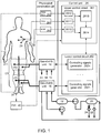
- FIG.1 The block diagram of the device for the impact on the cardiovascular system is demonstrated in the FIG.1 .
- Pneumatic connections are drawn with a solid line, and electrical links are drawn with a dotted line.
- a patient is designated at position 1.
- the device contains: the source 10 of compressed air, e.g. a compressor of the Becker manufacturer (the model DT 4.40) with a built-in regulator-limiter of the output pressure, the receiver 12, gas-distribution units 16 according to number of independent groups of compression cuffs 17, the source 18 of high pressure, e.g. a compressor of the Thomas manufacturer (the model 7006), the receiver 20 of the negative pressure.
- the source 10 of compressed air e.g. a compressor of the Becker manufacturer (the model DT 4.40) with a built-in regulator-limiter of the output pressure
- the receiver 12 gas-distribution units 16 according to number of independent groups of compression cuffs 17, the source 18 of high pressure, e.g. a compressor of the Thomas manufacturer (the model 7006), the receiver 20 of the negative pressure.
- Both the non-return spring-assisted valve 24 for creation of the negative pressure level in the receiver 20 and the valve 22 used for quick pressure release from the receiver 20 into the environment, are connected to the receiver
- the device contains the control and indication unit 26 and the associated unit 28 used for measurements of the patient's physiological parameters.
- the unit 28 is connected to electrodes 29 positioned on the patient's body and used for registration of the ECG, to the compression cuff 30 of the blood pressure measurer, the digital sensor 31 or 311, e.g. taken from a pulse oximeter for registration of plethysmograph.
- the unit 28 contains the ECG analyzer 281, and the blood pressure measurer 282, device for plethysmogram measurement 283, e.g. a pulse oxymeter, output of which are connected to the unit 26 with the use of standard interfaces, e.g. USB.
- the device 40 united with the unit 26 for registration of the temperature in the peripheral parts of the affected extremity was developed. This may be done, e.g. in the form of thermistor, attached to the peripheral area of an affected extremity (to a finger or toe) or in the form of a contactless appliance for measurement and analysis of the temperature spatial distribution, e.g. computer-assisted thermographic recorder.
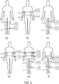
- FIG.1 shows one of the possible configurations of superposition of compression cuffs 17 applied to the patient 1: two cuffs 171 on the calves and two cuffs 172 on the thigh are put over the lower extremity; these are connected to suitable gas-distribution units 16 (other configurations are shown in the FIG.2 ).
- the unit 26 is equipped with a two-level control circuit.
- the upper control circuit 261 is designed for instance on the basis of a personal computer capable of analysis of the physiological signals concerning the patient's condition and sending control commands for the lower control circuit 262.
- the circuits 261, 262 are connected to each other by means of a double-sided digital communication interface for data exchange and management.
- the upper control circuit 261 contains:
- the lower circuit 262 is designed in the form of a microprocessor-based controller for generation of controlling signals for gas-distributing units 16, and it contains generators 2621...262n of controlling signals that correspond the number n of the units 16.
- Each of the gas-distribution units 16 contains: electromechanical distributors 161 and 162 for management of pneumatic mechanical quick exhaust air valves 165 for pressure pumping into a cuff, the electromechanical distributors 163 and 164 to control pneumatic mechanical quick exhaust air valve 167 for pressure release from the cuff, the pressure sensor 166 in the cuff.
- the pneumatic inlet valve 165 is connected with the source 10 via the receiver 12.
- the controlling pneumatic inlet of the valve 165 is connected to a pneumatic outlet of the distributor 161, the pneumatic outlet of which is connected to the negative pressure receiver 20 or with the atmosphere (environment), and with pneumatic outlet of the distributor 162 the pneumatic inlet of which is connected to the source of the high pressure 18.
- the pneumatic outlet of the device 165 is connected to a corresponding compression cuff.
- the pneumatic inlet of the valve 167 is connected to a corresponding compression cuff; the controlling pneumatic inlet is connected to the pneumatic outlet of the distributor 163 the pneumatic inlet of which is connected to the high pressure source 18, and with the pneumatic outlet of the distributor 164, the pneumatic inlet of which is connected to the receiver 20 of the negative pressure.
- the pneumatic outlet of the valve 167 is connected to the input of the receiver 20.
- the pneumatic inlet of the pressure sensor 166 is connected to a corresponding compression cuff, and the electrical output as well as electrical inputs of the distributors 161 to 164, are connected to the control and indication unit 26.
- the device produces the antegrade blood flow wave as follows.
- a-e, compression cuffs 17 are put over one or several extremities of the patient 1, and electrodes 29 for ECG registration, the compression cuff 30 for measurement of the blood pressure, and finger sensor 31 or 311 for plethysmogram registration are attached.
- the sensor 31 is placed over a distal part e.g. a finger or toe of the extremity to which a periodical compression exposure is provided. Then power supply to units 26, 28 of the sources 10 and 18 is connected.
- the unit 26 provides analysis and visualization of the physiological signals received from the unit 28: registered with ECG analyzer 281, the blood pressure measurer 282, and the device for plethysmogram registration 283. Information gathered due to measurements and analysis is represented on the computer's screen that allows a physician to choose a mode of impact.
- the unit 26 capable of the control of sending pressure impulses to independent groups of cuffs 17 with various delays in relation to R-peaks of the current QRS-complex of the ECG.
- the beginning of the pressure impulse in relation to the beginning of the pressure impulse in the proximal cuff 172 placed over the thigh is delayed for the transmission time of the pulse wave between cuffs 172 and 171.
- Sending pressure impulses to the cuffs is stopped simultaneously prior to initiation of the following QRS-complex.
- the method, implemented with the use of the device may be performed with several pairs of simultaneously functioning compression cuffs (placed to the thigh and calf, to the arm and the forearm of each extremity) connected to gas-distribution units 16 with the corresponding cuffs in a parallel way (see FIG.2 ).
- the values of impulse pressures are set with an excess of the systolic pressure in the arteries of extremities, mainly by 10 to 50 mm Hg that provides complete occlusion of vessels of the extremities.
- the values of impulse pressures in the distal area of the compression are set below the values of pressure impulses assigned for the proximal area of the compression, mainly by 10 to 40 mm Hg.
- Such a mode guarantees occlusion of the distal area.
- Such a mode is capable of providing compression of the vessels of the distal area and creation of the antegrade pressure wave.
- t 1 t C + T
- t C is the value set within a range of time points starting from the moment of the aortic valve opening till the moment of the aortic valve closing
- T means the transmission time of the pulse wave from the aortic orifice to the compression area.
- ECG chart diagrams of the systolic pressure in different regions of the cardiovascular system and charts of the pressure in the cuffs.
- the charts of the blood pressure in different regions of the cardiovascular system shown in the FIG.3 represent approximate pressure dynamics without any effect, and the charts include: blood pressure chart in aorta (P aorta ), pressure chart in the left ventricle of the heart (P lv ), blood pressure chart in the region of the proximal cuff (P prox ) e.g. in the thigh, blood pressure chart in the distal cuff (P dist ) e.g. over the calf.
- An increase of pressure in aorta during the systole is associated with the ejection phase, the beginning of which is approximately 30 to 60 msec after the R-peak of the ECG.
- the end of ejection phase is associated with the closing of the aortic valve (time point t d ). Then isovolumic relaxation starts for around 50 msec, and is followed by the diastole. The ending of the ejection phase and the beginning of the diastolic phase corresponds approximately to the time of expiration of the T-wave on the ECG chart and commonly continues for 270 to 400 msec following the R-peak that mainly depends on the heart rate. The maximum value of pressure in aorta is seen during the ejection phase, 200 to 300 msec after the R-peak on the ECG (time point S aorta ).
- a pulse wave generates in aorta and it spreads from the heart in the antegrade direction. Its velocity in aorta and major arteries is approximately 4 to 7 m per sec.
- the natural pulse wave spreads from the heart to the proximal area of compression e.g. to the thigh during the time T that lasts approximately 70 to 100 msec.
- the curve of pressure in the area of proximal cuffs location P prox resembles the curve of pressure in the aorta P aorta with adding the T value delay for the transmission time of the pulse wave.
- Compression of the proximal area and the arteries in the site of the proximal cuffs location leads to appearance of the pressure waves at higher and lower levels regarding the compression site because of ejection of the blood from the compressed arteries.
- the time of the transmission is equal to the time of the ejection phase delayed by the time of transmission of a natural pulse wave from the aorta orifice to the area of compression.
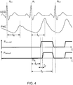
- the pressure diagrams P prox.cuff. and P dist.cuff. in the proximal and distal cuffs, respectively, are the impulses that begin after the delay t 1 and t 1 +t 2 following the time of the R-peak, respectively.
- the delay t 1 that concerns the onset of compression in the proximal cuffs required for achieving the maximum reinforcement of the antegrade wave is approximately equal to the sum of timepoints of the maximum pressure (S aorta ) and time T of transmission of the pulse wave from the aorta to the mentioned location and, commonly, is in average 270 to 370 msec.
- the time t 1 which represents generation of the compression impulse actually may start even 50 to 100 msec earlier lasting 170 to 320 msec.
- compression of the proximal area is associated with appearance of a retrograde pressure wave which summarizes with the naturally occurring wave including the aortic segment.
- a retrograde pressure wave which summarizes with the naturally occurring wave including the aortic segment.
- Fulfillment of the condition allows the retrograde pressure wave to reach the aortic orifice during the diastole phase producing useful haemodynamic physiological effects which are similar to those seen at performing the external counterpulsation.
- the beginning of the pressure impulse in the distal cuff is delayed in relation to the proximal one by the time t 2 of pulse wave transmission between the cuffs that is about 30 to 60 msec if the pair thigh-calf is used.
- the operation algorithm of the unit 2614 used for synchronization and control of the time characteristics of the compression impulses is given in the FIG.5 according to designations provided in the cyclogram FIG.3 .
- optimization of the delay t 1 and t 1 +t 2 following the time of the R-peak used for the onset of compression to the proximal and distal areas, respectively, may be performed as follows (see FIGS.4 , 6 ):
- the claimed method realized with the use of the suggested device is effective even in case of arrhythmia which may occur during the procedure.
- thermometry it is necessary to register any local change of the temperature, e.g. using a thermistor placed over a finger of the affected extremity or using contactless measuring equipment and analysis of spatial temperature distribution with a computer-assisted temperature recorder.
- a means for registration of tissue oxygen saturation in the peripheral area of the affected extremity also can be used. The mentioned methods allow us to optimise the impact, to assess physiological changes in the extremities being impacted and to correct the duration of the procedure.
- Session duration is 40 to 60 min every other day, totally 7 to 10 sessions. It is appropriate to conduct two to three treatment cycles per year.
- the compression cuff 173 is attached to buttocks, compression cuffs 172 are attached to the thighs and the compression cuffs 171 are attached to calves; all the cuffs are connected to corresponding gas-distribution units 16 (see FIG.2,f ).
- the source 18 of high pressure for generation of controlling pressure ( ⁇ 150Kpa) is switched on; it is followed by switching on the compression air source 10.
- the distributor 161 Within the time of growth of pressure in the receiver 12, while the distributor 161 is closed, impulses of controlling pressure for locking the valve 165 are generated with the distributor 162.
- the distributor 163 While the distributor 163 is closed, to connect the cuffs 171 to 173 to the receiver 20 via the valve 167, the distributor 164 connects the control input of the valve 167 to the receiver 20.
- the device As a working level of pressure in the receiver 12 is achieved, the device (according to the time diagram, FIG.9 ) enables the operation algorithm ( FIG.10 ).
- the unit 28 uses the signals received from the unit 2611 which analyses the ECG for determining the time point T R of the current R-peak on the ECG. As the set delay time t 0 has elapsed, the unit 26 generates the controlling signals for inflation of the distal cuffs e.g. cuffs 171 over the calf. Then as the delay time t 1 after inflating the calf cuff 171 is run, the unit 26 generates controlling signals for inflation of more proximal, located on the thigh, cuffs 172.
- the unit 26 As time delay t 2 since the time point of pressure pumping into the cuffs 172 placed on the thighs has elapsed, the unit 26 generates controlling signals for pumping pressure into the more proximal cuff 173 placed on the buttock. After elapsing the time interval t 3 since the time following air pumping into the cuff 171, the unit 26 generates controlling signals for simultaneous pressure release from all the cuffs 171 to 173.
- the distributor 164 is sent with a control voltage which switches off the control input of the valve 167 from the receiver 20, and then the distributor 163 is sent with a required voltage. At that pressure from the source 18 or from the receiver 12 goes to the control input of the valve 167, and it switches off the cuffs from the negative pressure receiver 20.
- the distributor 161 is sent with a short impulse (approximately 30 msec) of the control voltage from the unit 26 that connects for this time the control input of the valve 165 with the negative pressure receiver 20 or with the environment and releases the locking pressure.
- the valve 165 is opened, and the compressed air passes from the receiver 12 into a cuff.
- a short impulse (duration approximately 15 msec) is sent from the unit 26 to the distributor 162.
- the distributor 162 is opened that creates the locking pressure at the control input of the valve 165.
- the process of pressure pumping into a cuff is controlled by the unit 26 on the basis of feedback signals from the cuff pressure sensor 166.
- the gas-distributing device 16 switches to the mode of supporting pressure in a cuff the level of which should be guaranteed till the moment of pressure release. At that, the cuff becomes switched off from the receiver 12 as well as from the receiver 20.
- the distributor 164 is opened that connects the control input of the valve 167 to the receiver 20.
- the valve 167 is opened, and the air passes from the cuff into the receiver 20.
- the negative pressure in the receiver 20 allows decreasing the time required to release an excessive pressure from the cuffs (to shorten the duration of the falling edge of the compression impulse) that is important for improving the efficacy of the impact on the cardiovascular system.
- the valve 22 for quick pressure release designed, for instance, in the form of an inverse valve, provides an additional decrease of the excessive pressure release time in the cuffs at the moment of their connection to the receiver 20 as it adds an additional way for release of a positive pressure from the cuffs. Furthermore, it provides pressure release from the pneumatic system of the device after the finishing of its work.
- the device for the impact on the cardiovascular system is more universal in terms of regulation and the use of physiological reactions of the cardiovascular system of a patient.
- the regulation is carried out by adjustment of amplitude-time parameters of compression impulses using the plethysmographic signals from the sensors 31 as the feedback.
- the unit 26 in the manual mode or automatically stops the impact procedure if any current parameter exceeds the predetermined limits of the cardiac contractions.
- the device allows generating pressure impulses into the compression cuffs 17 with omissions so that the ratio of the number of compression cycles to the amount of cardiac cycles would range from 1/1 to 1/4.
- the upper control circuit of the unit 26 provides the processing of cardiac rhythm parameters, processing of the statistical, geometrical, correlational and frequency parameters of the cardiac rhythm as well as calculation of the integrating index of the activity of the regulatory systems (IARS) of a patient.
- IARS regulatory systems
- the processing can be accomplished for obtaining diagnostic data that concerns the procedure impact on the cardiovascular system.
- the therapeutic effect of the claimed method is confirmed by its clinical use as well as by thermograms certifying the efficacy of the method; these are shown in the FIG.7 .
- Thermographic changes in the lower extremities were registered with the use of the computer-assisted recording thermometer IRTIS-2000 (www.irtis.ru). There is the temperature scale on the right side; numerical marks show values of the temperature in the affected areas.
- ABP on the humeral artery 120/88 mm Hg; on the right foot 65 mm Hg, on the left foot 65 mm Hg.
- stenosis of the right common femoral artery is 22%; stenosis of the left common femoral artery is 52%.
- Occlusion of the anterior femoral arteries bilateral at the level of the Gunther's channel.
- Diagnosis Chronic obliterating disease of the arteries of the lower extremities, 2B stage according to Fontaine-Pokrovsky.
- the patient underwent a course of 10 sessions of the patent-pending method of treatment for the disease of the lower extremities. Duration of each session was 50 minutes. Compression cuffs were placed over the middle part of the thighs and upper third of calves. The pressure impulse in the femoral cuffs was generated with the delay 200 ⁇ 50 msec after the R-peak on the ECG. The pressure impulse in shin cuffs was generated with the delay 50 msec after the beginning of action in the femoral cuffs. Amplitude of the pressure in the cuffs was set by 20 to 40 mm Hg higher than the level of the current arterial blood pressure. For a prompt control of the blood flow, a finger/toe sensor was placed for plethysmogram registration.
- the amplitude of arterial pulsation in the lower extremity registered by the plethysmographic sensor is characterized by 5- to 7-fold increase.
- Means and components that provide generation and control of pressure impulses in the cuffs may be designed based on the modern hardware components of pneumatic automation and in the way that it is realized in the devices «CARDIOPULSAR»® (www.constel.ru) for supplementary blood circulation with the use of the method of external counterpulsation.
Landscapes
- Health & Medical Sciences (AREA)
- Life Sciences & Earth Sciences (AREA)
- Cardiology (AREA)
- Heart & Thoracic Surgery (AREA)
- Engineering & Computer Science (AREA)
- Public Health (AREA)
- Veterinary Medicine (AREA)
- General Health & Medical Sciences (AREA)
- Animal Behavior & Ethology (AREA)
- Biomedical Technology (AREA)
- Pathology (AREA)
- Biophysics (AREA)
- Medical Informatics (AREA)
- Molecular Biology (AREA)
- Surgery (AREA)
- Physics & Mathematics (AREA)
- Vascular Medicine (AREA)
- Physiology (AREA)
- Physical Education & Sports Medicine (AREA)
- Rehabilitation Therapy (AREA)
- Epidemiology (AREA)
- Pain & Pain Management (AREA)
- Ophthalmology & Optometry (AREA)
- Computer Vision & Pattern Recognition (AREA)
- Artificial Intelligence (AREA)
- Signal Processing (AREA)
- Psychiatry (AREA)
- Mechanical Engineering (AREA)
- Anesthesiology (AREA)
- Hematology (AREA)
- Emergency Medicine (AREA)
- Pulmonology (AREA)
- Measuring Pulse, Heart Rate, Blood Pressure Or Blood Flow (AREA)
- External Artificial Organs (AREA)
- Ultra Sonic Daignosis Equipment (AREA)
Claims (15)
- Einrichtung zur Beeinflussung eines kardiovaskulären Systems, die Folgendes enthält:- mindestens ein Paar unabhängiger Kompressionsmanschetten (17),- eine Druckluftquelle (10),- Gasverteilungseinheiten (10),- eine Steuer- und Anzeigeeinheit (26),- einen Analysierer des ECG QRS-Komplexes (29, 281, 2611),- eine Einheit (31, 311, 283, 2612) zur Registrierung des Blutflusses in den Extremitäten,dadurch gekennzeichnet, dass- die Kompressionsmanschetten (17) mindestens proximale (172, 175) und distale (171, 174) Manschetten aufweisen, die um mindestens eine Extremität zur Schaffung einer periodischen Kompression angeordnet und mit einer Druckluftquelle (10) über die Gasverteilungseinheiten (16) verbunden sind,- die Steuer- und Anzeigeeinheit (26) mit den Gasverteilungseinheiten (16), dem Analysierer des ECG QRS-Komplexes (29, 281, 2611) und der Einheit (31, 311, 283, 2612) zur Registrierung des Blutflusses in der Extremität verbunden ist,- die Steuer- und Anzeigeeinheit die Zuführung von Druckimpulsen in die genannten Manschetten (17) mit einer Verzögerung in Bezug auf die R-Spitze des Strömungs-QRS-Komplexes steuern kann, so dass der Impuls in einer proximalen Manschette (172, 175) beim Ankommen einer Blutdruckimpulswelle vom Herzen zur erwähnten proximalen Manschette beginnt und die Größe der Verzögerung des Beginns des Druckimpulses in der genannten proximalen Manschette mit der Impulswellenlaufzeit zwischen den genannten Manschetten übereinstimmt, wobei der Abschaltpunkt der Druckimpulse in den genannten proximalen (172, 175) und distalen (171, 174) Manschetten gleich ist und früher als der Beginn des folgenden QRS-Komplexes erfolgt und wobei die Einheit (31, 311, 283, 2612) zur Registrierung des Blutflusses in der Extremität distal in Bezug auf die Orte der Kompressionsmanschetten (17) angeordnet ist, und- die Steuer- und Anzeigeeinheit (26) eine Korrektur der Druckimpulsparameter auf der Basis der genannten Registrierung des distal zu den Kompressionsmanschetten fließenden Blutflusses in folgender Weise vornehmen kann:- die Verzögerungen zwischen den R-Spitzen des Strömungs-QRS-Komplexes und den Maximalwerten der Blutdruckimpulswellen in Abwesenheit und in Anwesenheit des genannten Druckimpulses werden bestimmt;- eine Unterschiedszeit Δt wird nach der Formel Δt = tb-t0 berechnet, wobei tb, t0 Verzögerungen zwischen R-Spitzen den Maximalwerten der Blutdruckimpulswellen beim Vorhandensein bzw. beim Nichtvorhandensein des genannten Druckimpulses sind,- die Front des Druckimpulses t1 in der genannten proximalen Manschette wird gemäß der folgenden Formel korrigiert: T1corr. = t1-Δt.
- Einrichtung nach Anspruch 1,
dadurch gekennzeichnet,
dass sie zwei Paare der genannten Manschetten (17), nämlich eine Oberschenkelmanschette (172) und eine Wadenmanschette (171) für jede untere Extremität aufweist, die mit der genannten Gasverteilungseinheit (16) in paralleler Weise verbunden ist. - Einrichtung nach Anspruch 1,
dadurch gekennzeichnet,
dass sie zwei Paare der genannten Manschetten (17), nämlich eine Oberarmmanschette und eine Unterarmmanschette für jede Extremität aufweist, die mit der genannten Gasverteilungseinheit (16) in paralleler Weise verbunden ist. - Einrichtung nach Anspruch 1,
dadurch gekennzeichnet,
dass sie vier Paare der genannten Manschetten (17), nämlich Manschetten für den Oberarm, Unterarm, Oberschenkel und die Wade für jede Extremität (175, 174, 172, 171) aufweist, die mit den genannten Gasverteilungseinheiten (16) in paralleler Weise verbunden sind. - Einrichtung nach Anspruch 1,
dadurch gekennzeichnet,
dass die Mittel (31, 311, 283, 2612) zur Registrierung des Blutflusses eine Einrichtung zur Registrierung eines Plethysmogramms ist. - Einrichtung nach Anspruch 1,
dadurch gekennzeichnet,
dass sie zusätzlich Mittel (40) zur Registrierung von Temperaturänderungen in einer peripheren Region der betreffenden Extremität während des Prozesses der periodischen Kompression aufweist. - Einrichtung nach Anspruch 6,
dadurch gekennzeichnet,
dass die Mittel (40) zur Registrierung von Temperaturänderungen Messungen und eine Analyse der räumlichen Verteilung der Temperatur vornehmen können. - Einrichtung nach Anspruch 1,
dadurch gekennzeichnet,
dass sie zusätzlich Mittel (31, 311, 283, 2612) zur Registrierung von Änderungen des Gewebe-Sauerstoffgehalts in einer peripheren Region der betreffenden Extremität während des Prozesses der periodischen Kompression aufweist. - Einrichtung nach Anspruch 1,
dadurch gekennzeichnet, dass- ein Empfänger (20) für negativen Druck in pneumatischer Verbindung mit der Eingangsleitung der Druckluftquelle (10) steht,- ein Empfänger (12) in pneumatischer Verbindung mit dem Ausgang der Druckluftquelle (10) steht,- eine Hochdruckquelle (18) vorgesehen ist,- jede Gasverteilungseinheit (16) zwei pneumatische, mechanisch schnelle Luftablassventile (165, 167), vier elektromechanische Verteiler (161-164) und einen Drucksensor (166) aufweist,- die Steuereingänge dieser pneumatischen, mechanisch schnellen Luftablassventile (165, 167) mit den genannten elektromechanischen Verteilern (161-164) mittels der Hochdruckquelle (18) und der Druckluftquelle (10) verbunden sind,- der Ausgang eines der genannten, pneumatischen, mechanisch schnellen Luftablassventile mit einer entsprechenden Kompressionsmanschette (16) verbunden ist und- der Ausgang eines anderen Luftablassventils mit dem genannten negativen Druck-Empfängers (20) verbunden ist. - Einrichtung nach Anspruch 1,
dadurch gekennzeichnet,
dass sie zusätzlich eine der genannten Steuer- und Anzeigeeinheit zugeordnete Messeinrichtung (30, 282) für den Blutdruck aufweist, die den Druck in den genannten Kompressionsmanschetten (16) abhängig vom Strömungswert des Blutdrucks korrigieren kann. - Einrichtung nach Anspruch 1,
dadurch gekennzeichnet,
dass sie eine Messeinrichtung (2611) für den Herzschlag aufweist, die mit der genannten Steuer- und Anzeigeeinheit (26) verbunden ist und die den Prall aufheben kann, wenn der Strömungsherzschlag außerhalb vorbestimmter Grenzen liegt. - Einrichtung nach Anspruch 9,
dadurch gekennzeichnet,
dass der genannte Empfänger (20) negativen Drucks mit einem Ventil (22) mit schnellem Druckablass und mit einem Einwegventil (24) ausgerüstet ist, das den erwähnten Empfänger (20) mit der Umgebung verbindet. - Einrichtung nach Anspruch 1,
dadurch gekennzeichnet,
dass die Aussendung der Druckimpulse in den genannte Druckbereich gestoppt wird, bevor der Einsatz des folgenden QRS-Komplexes vorzugsweise 0,02 bis 0,1s davor erfolgt. - Einrichtung nach Anspruch 13,
dadurch gekennzeichnet,
dass die Berechnung des Einsatzes des folgenden QRS-Komplexes gemäß der folgenden Formel durchgeführt wird: t(QRS i +1) = t(QRSi) + <RR>, wobei t(QRSi) und t(QRS1 ) der Strömungseinsatz und der Strömungseinsatz des nächsten QRS-Komplexes sind, sowie <RR> = < t(QRSi) - t(QRSi-1)> die mittlere Dauer des Herzzyklus ist, die auf der Basis mehrerer vorhergehender Perioden von Herzkontraktionen berechnet wird. - Einrichtung nach Anspruch 1,
dadurch gekennzeichnet,
dass die genannte Steuer- und Anzeigeeinheit (26) für ein Verhältnis einer Anzahl von Kompressionszyklen in den genannten Kompressionsmanschetten (17) zu einer Anzahl von QRS-Komplexzyklen sorgt, das von 1/1 bis 1/4 bemessen ist.
Applications Claiming Priority (3)
| Application Number | Priority Date | Filing Date | Title |
|---|---|---|---|
| RU2010127469/14A RU2440828C1 (ru) | 2010-07-06 | 2010-07-06 | Устройство для воздействия на сердечно-сосудистую систему |
| RU2010131388/14A RU2446783C1 (ru) | 2010-07-27 | 2010-07-27 | Способ лечения хронических облитерирующих заболеваний артерий конечностей и устройство для его осуществления |
| PCT/RU2011/000487 WO2012005630A2 (en) | 2010-07-06 | 2011-07-05 | Method and devices proposed for the impact on the cardiovascular system |
Publications (3)
| Publication Number | Publication Date |
|---|---|
| EP2571545A2 EP2571545A2 (de) | 2013-03-27 |
| EP2571545A4 EP2571545A4 (de) | 2013-07-24 |
| EP2571545B1 true EP2571545B1 (de) | 2017-11-22 |
Family
ID=45441697
Family Applications (1)
| Application Number | Title | Priority Date | Filing Date |
|---|---|---|---|
| EP11803874.4A Not-in-force EP2571545B1 (de) | 2010-07-06 | 2011-07-05 | Verfahren und vorrichtungen zur einwirkung auf das herz-kreislauf-system |
Country Status (4)
| Country | Link |
|---|---|
| US (1) | US9265693B2 (de) |
| EP (1) | EP2571545B1 (de) |
| CN (1) | CN102971022B (de) |
| WO (1) | WO2012005630A2 (de) |
Families Citing this family (30)
| Publication number | Priority date | Publication date | Assignee | Title |
|---|---|---|---|---|
| ITBO20120219A1 (it) * | 2012-04-19 | 2013-10-20 | Eurtronik Studioerre S R L Con Uni Co Socio | Apparato di stimolazione neuro-muscolare |
| US9592177B2 (en) * | 2012-11-26 | 2017-03-14 | Sayed Nour | Circulatory flow restoration device |
| CN103690332B (zh) * | 2013-12-16 | 2015-07-29 | 同济大学 | 一种具有抗休克功能的按摩椅 |
| CN104027097A (zh) * | 2014-06-06 | 2014-09-10 | 首都医科大学 | 血管功能无创检测方法及装置 |
| CN104000712A (zh) * | 2014-06-13 | 2014-08-27 | 广州阳普医疗科技股份有限公司 | 一种肢体缺血治疗仪及其控制方法 |
| US10258536B2 (en) * | 2014-08-27 | 2019-04-16 | Matthew Thomas OBERDIER | External peripheral vascular occlusion for enhanced cardiopulmonary resuscitation |
| US10791943B2 (en) * | 2015-04-03 | 2020-10-06 | Pression Llc | System and method for synchronizing external compression of a limb for increased blood |
| WO2016207884A1 (en) * | 2015-06-21 | 2016-12-29 | Yissum Research Development Company Of The Hebrew University Of Jerusalem Ltd. | Detection of peripheral arterial disease |
| US10646672B2 (en) * | 2015-06-26 | 2020-05-12 | Koninklijke Philips N.V. | Positive pressure pulses cardio-pulmonary resuscitation device |
| EP3135326A1 (de) * | 2015-08-24 | 2017-03-01 | Berlin Heart GmbH | Herzpumpe sowie verfahren zum betrieb einer herzpumpe |
| US10667984B2 (en) * | 2015-12-18 | 2020-06-02 | Stryker Corporation | Systems and methods for operating patient therapy devices |
| SG10202104647WA (en) * | 2015-12-30 | 2021-06-29 | Syncardon Llc | Apparatus and method for promoting wound healing |
| WO2017189926A1 (en) | 2016-04-27 | 2017-11-02 | Radial Medical, Inc. | Adaptive compression therapy systems and methods |
| TWI632903B (zh) * | 2017-02-13 | 2018-08-21 | 長庚大學 | Control method of external counterpulsation system |
| CN111163695B (zh) * | 2017-09-29 | 2023-09-12 | 京瓷株式会社 | 睡眠判定系统、按摩系统、控制方法及电子设备 |
| CN107714419A (zh) * | 2017-11-14 | 2018-02-23 | 首都医科大学附属北京天坛医院 | 下肢循环辅助按摩装置 |
| WO2019136429A1 (en) * | 2018-01-08 | 2019-07-11 | Michael Poon | External counterpulsation system |
| KR101935830B1 (ko) | 2018-02-13 | 2019-01-07 | 주식회사 오스테오시스 | 외부역박동시스템과 그 제어방법 |
| EP3755243B1 (de) * | 2018-03-05 | 2024-05-29 | Western Clinical Engineering Ltd. | Personalisiertes tourniquet zur intermittierenden vaskulären okklusion |
| KR101933519B1 (ko) * | 2018-07-09 | 2018-12-28 | 주식회사 오스테오시스 | 외부역박동시스템과 그 제어방법 |
| CN110279574B (zh) * | 2019-07-24 | 2021-09-21 | 四川大学华西医院 | 用于防治肌少症的局部振动装置 |
| MX2022010303A (es) * | 2020-02-20 | 2022-09-19 | Academia Sinica | Sistema de contrapulsacion externa de alta eficacia y metodo de tratamiento que utiliza el sistema. |
| CN111603375B (zh) * | 2020-05-11 | 2022-06-24 | 山西征宇农业工程有限公司 | 一种自动脉冲复苏系统 |
| IT202000015256A1 (it) * | 2020-06-25 | 2021-12-25 | Univ Cattolica Del Sacro Cuore | Dispositivo per il trattamento dell'idrocefalo |
| CN113018135B (zh) * | 2021-02-24 | 2023-01-31 | 山东交通学院 | 体外反搏协同控制系统及方法 |
| CN113288751B (zh) * | 2021-05-24 | 2023-06-23 | 中山大学附属第一医院 | 一种用于改善血管内皮功能的便携式装置 |
| TWI772089B (zh) * | 2021-07-02 | 2022-07-21 | 陳羿愷 | 心血管檢測系統及其實施方法 |
| CN115363928A (zh) * | 2022-09-15 | 2022-11-22 | 四川千里倍益康医疗科技股份有限公司 | 腿部气压按摩仪的控制方法及腿部气压按摩仪 |
| CN115645734B (zh) * | 2022-09-26 | 2025-01-28 | 安徽通灵仿生科技有限公司 | 体外反搏治疗冠心病的效果评价方法、系统及存储介质 |
| CN117379683B (zh) * | 2023-12-12 | 2024-02-27 | 苏州晟智医疗科技有限公司 | 反搏辅助装置、计算设备、存储介质及反搏系统 |
Citations (2)
| Publication number | Priority date | Publication date | Assignee | Title |
|---|---|---|---|---|
| US20030009119A1 (en) * | 2001-03-23 | 2003-01-09 | Kamm Roger D. | Method and apparatus for stimulating angiogenesis and wound healing by use of external compression |
| US20030233061A1 (en) * | 2002-06-13 | 2003-12-18 | Hui John C. K. | External counterpulsation and method for minimizing end diastolic pressure |
Family Cites Families (17)
| Publication number | Priority date | Publication date | Assignee | Title |
|---|---|---|---|---|
| US3835845A (en) * | 1972-10-24 | 1974-09-17 | Medical Innovations Inc | Cardiac synchronization system and method |
| US4077402A (en) * | 1976-06-25 | 1978-03-07 | Benjamin Jr J Malvern | Apparatus for promoting blood circulation |
| CN85200905U (zh) * | 1985-04-01 | 1985-09-10 | 中山医学院 | 微机化增强型体外反搏装置 |
| US4753226A (en) * | 1985-04-01 | 1988-06-28 | Biomedical Engineering Development Center of Sun Yat-Sen University of Medical Science | Combination device for a computerized and enhanced type of external counterpulsation and extra-thoracic cardiac massage apparatus |
| RU2112492C1 (ru) * | 1992-05-14 | 1998-06-10 | Научно-исследовательский институт трансплантологии и искусственных органов АМН РФ | Способ вспомогательного кровообращения и устройство для его реализации |
| US5514079A (en) * | 1992-08-11 | 1996-05-07 | Dillon; Richard S. | Method for promoting circulation of blood |
| US6863670B2 (en) * | 1993-05-06 | 2005-03-08 | Vasomedical, Inc. | High efficiency external counterpulsation apparatus and method for controlling same |
| RU2108771C1 (ru) * | 1995-10-25 | 1998-04-20 | Александр Иванович Суханов | Способ лечения больных облитерирующим эндартериитом |
| US6589267B1 (en) * | 2000-11-10 | 2003-07-08 | Vasomedical, Inc. | High efficiency external counterpulsation apparatus and method for controlling same |
| US8043239B2 (en) * | 2001-05-10 | 2011-10-25 | Pptt, Llc | External counterpulsation (ECP) device for use in an ambulance or the like for heart attack patients to limit heart muscle damage |
| CN2536221Y (zh) * | 2001-09-20 | 2003-02-19 | 杨辰圆 | 变频式移动体外反搏装置 |
| US7244225B2 (en) * | 2003-10-07 | 2007-07-17 | Cardiomedics, Inc. | Devices and methods for non-invasively improving blood circulation |
| US20050126578A1 (en) * | 2003-12-12 | 2005-06-16 | Garrison Richard L. | External pressure garment in combination with a complementary positive pressure ventilator for pulmocardiac assistance |
| US7074177B2 (en) * | 2004-06-30 | 2006-07-11 | David Anthony Pickett | High-efficiency external counterpulsation apparatus and method for performing the same |
| US20060058716A1 (en) * | 2004-09-14 | 2006-03-16 | Hui John C K | Unitary external counterpulsation device |
| WO2007008201A1 (en) * | 2005-07-06 | 2007-01-18 | David Anthony Pickett | High-efficiency external counterpulsation apparatus and method for performing the same |
| DE102010048519B4 (de) * | 2010-10-14 | 2016-12-22 | Charité-Universitätsmedizin Berlin | Gerät zur Therapie von peripheren Durchblutungsstörungen im Bereich der unteren Extremitäten |
-
2011
- 2011-07-05 EP EP11803874.4A patent/EP2571545B1/de not_active Not-in-force
- 2011-07-05 WO PCT/RU2011/000487 patent/WO2012005630A2/en not_active Ceased
- 2011-07-05 US US13/699,880 patent/US9265693B2/en active Active
- 2011-07-05 CN CN201180033462.8A patent/CN102971022B/zh not_active Expired - Fee Related
Patent Citations (2)
| Publication number | Priority date | Publication date | Assignee | Title |
|---|---|---|---|---|
| US20030009119A1 (en) * | 2001-03-23 | 2003-01-09 | Kamm Roger D. | Method and apparatus for stimulating angiogenesis and wound healing by use of external compression |
| US20030233061A1 (en) * | 2002-06-13 | 2003-12-18 | Hui John C. K. | External counterpulsation and method for minimizing end diastolic pressure |
Also Published As
| Publication number | Publication date |
|---|---|
| US20130102939A1 (en) | 2013-04-25 |
| WO2012005630A2 (en) | 2012-01-12 |
| US9265693B2 (en) | 2016-02-23 |
| CN102971022B (zh) | 2016-06-29 |
| EP2571545A2 (de) | 2013-03-27 |
| EP2571545A4 (de) | 2013-07-24 |
| CN102971022A (zh) | 2013-03-13 |
| WO2012005630A3 (en) | 2012-02-23 |
Similar Documents
| Publication | Publication Date | Title |
|---|---|---|
| EP2571545B1 (de) | Verfahren und vorrichtungen zur einwirkung auf das herz-kreislauf-system | |
| US7048702B2 (en) | External counterpulsation and method for minimizing end diastolic pressure | |
| EP3426136B1 (de) | Vorrichtung zur förderung der wundheilung | |
| RU2291723C2 (ru) | Способ лечения живого организма для сокращения нагрузки на сердце и устройство для осуществления этого способа | |
| US11877836B2 (en) | System and method for synchronizing external compression of a limb for increased blood flow | |
| US6589267B1 (en) | High efficiency external counterpulsation apparatus and method for controlling same | |
| JP5449394B2 (ja) | 循環及び血行動態補助のための拍動性があり非侵襲性の装置 | |
| US20030233118A1 (en) | Method for treating congestive heart failure using external counterpulsation | |
| SG182872A1 (en) | Apparatus and method for altering the arterial pulse waveform of a body | |
| JP2007510447A (ja) | 人間または哺乳動物を治療するためのカウンタパルセーション電気治療装置 | |
| JP6410576B2 (ja) | 加圧制御装置および加圧制御方法 | |
| US20100262022A1 (en) | Detection of Progressive Central Hypovolemia using the System of the present invention with Pulse-Decomposition Analysis (PDA) | |
| US20150148694A1 (en) | Detection of progressive central hypovolemia | |
| RU2446783C1 (ru) | Способ лечения хронических облитерирующих заболеваний артерий конечностей и устройство для его осуществления | |
| RU2644927C1 (ru) | Способ работы системы управляемой прерывистой пневмокомпрессии верхних и нижних конечностей с оценкой биомеханики сосудов | |
| Ramasamy | Enhanced External Counterpulsation Waveform Interpretation and Clinical Application: A Primer and Case-Based Troubleshooting Guide | |
| Huang et al. | Peripheral hemodynamic effects of synchronizing intermittent compression with cardiac pulsation | |
| Sudarev et al. | The Method and Apparatus for Peripheral Arterial Disease Treatment. | |
| Weyer et al. | Model-based optimization of adaptive external counterpulsation therapy | |
| WO2003105746A1 (en) | Method for treating congestive heart failure using external counterpulsation | |
| Soran et al. | Enhanced External Counterpulsation Therapy in Coronary Artery Disease Management |
Legal Events
| Date | Code | Title | Description |
|---|---|---|---|
| PUAI | Public reference made under article 153(3) epc to a published international application that has entered the european phase |
Free format text: ORIGINAL CODE: 0009012 |
|
| 17P | Request for examination filed |
Effective date: 20121219 |
|
| AK | Designated contracting states |
Kind code of ref document: A2 Designated state(s): AL AT BE BG CH CY CZ DE DK EE ES FI FR GB GR HR HU IE IS IT LI LT LU LV MC MK MT NL NO PL PT RO RS SE SI SK SM TR |
|
| A4 | Supplementary search report drawn up and despatched |
Effective date: 20130626 |
|
| RIC1 | Information provided on ipc code assigned before grant |
Ipc: A61B 5/0402 20060101ALI20130620BHEP Ipc: A61H 33/00 20060101ALN20130620BHEP Ipc: A61H 31/00 20060101ALI20130620BHEP Ipc: A61H 9/00 20060101ALI20130620BHEP Ipc: A61M 1/10 20060101AFI20130620BHEP |
|
| DAX | Request for extension of the european patent (deleted) | ||
| 17Q | First examination report despatched |
Effective date: 20150629 |
|
| RIC1 | Information provided on ipc code assigned before grant |
Ipc: A61H 9/00 20060101ALI20170518BHEP Ipc: A61H 33/00 20060101ALN20170518BHEP Ipc: A61B 5/0402 20060101ALI20170518BHEP Ipc: A61M 1/10 20060101AFI20170518BHEP Ipc: A61H 31/00 20060101ALI20170518BHEP |
|
| GRAP | Despatch of communication of intention to grant a patent |
Free format text: ORIGINAL CODE: EPIDOSNIGR1 |
|
| RIC1 | Information provided on ipc code assigned before grant |
Ipc: A61B 5/0402 20060101ALI20170529BHEP Ipc: A61H 31/00 20060101ALI20170529BHEP Ipc: A61H 33/00 20060101ALN20170529BHEP Ipc: A61H 9/00 20060101ALI20170529BHEP Ipc: A61M 1/10 20060101AFI20170529BHEP |
|
| INTG | Intention to grant announced |
Effective date: 20170623 |
|
| RIN1 | Information on inventor provided before grant (corrected) |
Inventor name: KOROTICH, EVGENY VLADIMIROVICH |
|
| RIN1 | Information on inventor provided before grant (corrected) |
Inventor name: KOROTICH, EVGENY VLADIMIROVICH Inventor name: SUDAREV, ALEKSEY MONESOVICH |
|
| GRAS | Grant fee paid |
Free format text: ORIGINAL CODE: EPIDOSNIGR3 |
|
| GRAA | (expected) grant |
Free format text: ORIGINAL CODE: 0009210 |
|
| STAA | Information on the status of an ep patent application or granted ep patent |
Free format text: STATUS: THE PATENT HAS BEEN GRANTED |
|
| AK | Designated contracting states |
Kind code of ref document: B1 Designated state(s): AL AT BE BG CH CY CZ DE DK EE ES FI FR GB GR HR HU IE IS IT LI LT LU LV MC MK MT NL NO PL PT RO RS SE SI SK SM TR |
|
| REG | Reference to a national code |
Ref country code: GB Ref legal event code: FG4D |
|
| REG | Reference to a national code |
Ref country code: CH Ref legal event code: EP |
|
| REG | Reference to a national code |
Ref country code: IE Ref legal event code: FG4D |
|
| REG | Reference to a national code |
Ref country code: AT Ref legal event code: REF Ref document number: 947821 Country of ref document: AT Kind code of ref document: T Effective date: 20171215 |
|
| REG | Reference to a national code |
Ref country code: DE Ref legal event code: R096 Ref document number: 602011043628 Country of ref document: DE |
|
| REG | Reference to a national code |
Ref country code: NL Ref legal event code: MP Effective date: 20171122 |
|
| REG | Reference to a national code |
Ref country code: LT Ref legal event code: MG4D |
|
| REG | Reference to a national code |
Ref country code: AT Ref legal event code: MK05 Ref document number: 947821 Country of ref document: AT Kind code of ref document: T Effective date: 20171122 |
|
| PG25 | Lapsed in a contracting state [announced via postgrant information from national office to epo] |
Ref country code: NO Free format text: LAPSE BECAUSE OF FAILURE TO SUBMIT A TRANSLATION OF THE DESCRIPTION OR TO PAY THE FEE WITHIN THE PRESCRIBED TIME-LIMIT Effective date: 20180222 Ref country code: LT Free format text: LAPSE BECAUSE OF FAILURE TO SUBMIT A TRANSLATION OF THE DESCRIPTION OR TO PAY THE FEE WITHIN THE PRESCRIBED TIME-LIMIT Effective date: 20171122 Ref country code: SE Free format text: LAPSE BECAUSE OF FAILURE TO SUBMIT A TRANSLATION OF THE DESCRIPTION OR TO PAY THE FEE WITHIN THE PRESCRIBED TIME-LIMIT Effective date: 20171122 Ref country code: FI Free format text: LAPSE BECAUSE OF FAILURE TO SUBMIT A TRANSLATION OF THE DESCRIPTION OR TO PAY THE FEE WITHIN THE PRESCRIBED TIME-LIMIT Effective date: 20171122 Ref country code: ES Free format text: LAPSE BECAUSE OF FAILURE TO SUBMIT A TRANSLATION OF THE DESCRIPTION OR TO PAY THE FEE WITHIN THE PRESCRIBED TIME-LIMIT Effective date: 20171122 Ref country code: NL Free format text: LAPSE BECAUSE OF FAILURE TO SUBMIT A TRANSLATION OF THE DESCRIPTION OR TO PAY THE FEE WITHIN THE PRESCRIBED TIME-LIMIT Effective date: 20171122 |
|
| PG25 | Lapsed in a contracting state [announced via postgrant information from national office to epo] |
Ref country code: AT Free format text: LAPSE BECAUSE OF FAILURE TO SUBMIT A TRANSLATION OF THE DESCRIPTION OR TO PAY THE FEE WITHIN THE PRESCRIBED TIME-LIMIT Effective date: 20171122 Ref country code: RS Free format text: LAPSE BECAUSE OF FAILURE TO SUBMIT A TRANSLATION OF THE DESCRIPTION OR TO PAY THE FEE WITHIN THE PRESCRIBED TIME-LIMIT Effective date: 20171122 Ref country code: HR Free format text: LAPSE BECAUSE OF FAILURE TO SUBMIT A TRANSLATION OF THE DESCRIPTION OR TO PAY THE FEE WITHIN THE PRESCRIBED TIME-LIMIT Effective date: 20171122 Ref country code: GR Free format text: LAPSE BECAUSE OF FAILURE TO SUBMIT A TRANSLATION OF THE DESCRIPTION OR TO PAY THE FEE WITHIN THE PRESCRIBED TIME-LIMIT Effective date: 20180223 Ref country code: BG Free format text: LAPSE BECAUSE OF FAILURE TO SUBMIT A TRANSLATION OF THE DESCRIPTION OR TO PAY THE FEE WITHIN THE PRESCRIBED TIME-LIMIT Effective date: 20180222 Ref country code: LV Free format text: LAPSE BECAUSE OF FAILURE TO SUBMIT A TRANSLATION OF THE DESCRIPTION OR TO PAY THE FEE WITHIN THE PRESCRIBED TIME-LIMIT Effective date: 20171122 |
|
| REG | Reference to a national code |
Ref country code: FR Ref legal event code: PLFP Year of fee payment: 8 |
|
| PG25 | Lapsed in a contracting state [announced via postgrant information from national office to epo] |
Ref country code: CZ Free format text: LAPSE BECAUSE OF FAILURE TO SUBMIT A TRANSLATION OF THE DESCRIPTION OR TO PAY THE FEE WITHIN THE PRESCRIBED TIME-LIMIT Effective date: 20171122 Ref country code: CY Free format text: LAPSE BECAUSE OF FAILURE TO SUBMIT A TRANSLATION OF THE DESCRIPTION OR TO PAY THE FEE WITHIN THE PRESCRIBED TIME-LIMIT Effective date: 20171122 Ref country code: SK Free format text: LAPSE BECAUSE OF FAILURE TO SUBMIT A TRANSLATION OF THE DESCRIPTION OR TO PAY THE FEE WITHIN THE PRESCRIBED TIME-LIMIT Effective date: 20171122 Ref country code: DK Free format text: LAPSE BECAUSE OF FAILURE TO SUBMIT A TRANSLATION OF THE DESCRIPTION OR TO PAY THE FEE WITHIN THE PRESCRIBED TIME-LIMIT Effective date: 20171122 Ref country code: EE Free format text: LAPSE BECAUSE OF FAILURE TO SUBMIT A TRANSLATION OF THE DESCRIPTION OR TO PAY THE FEE WITHIN THE PRESCRIBED TIME-LIMIT Effective date: 20171122 |
|
| REG | Reference to a national code |
Ref country code: DE Ref legal event code: R097 Ref document number: 602011043628 Country of ref document: DE |
|
| PG25 | Lapsed in a contracting state [announced via postgrant information from national office to epo] |
Ref country code: RO Free format text: LAPSE BECAUSE OF FAILURE TO SUBMIT A TRANSLATION OF THE DESCRIPTION OR TO PAY THE FEE WITHIN THE PRESCRIBED TIME-LIMIT Effective date: 20171122 Ref country code: PL Free format text: LAPSE BECAUSE OF FAILURE TO SUBMIT A TRANSLATION OF THE DESCRIPTION OR TO PAY THE FEE WITHIN THE PRESCRIBED TIME-LIMIT Effective date: 20171122 Ref country code: SM Free format text: LAPSE BECAUSE OF FAILURE TO SUBMIT A TRANSLATION OF THE DESCRIPTION OR TO PAY THE FEE WITHIN THE PRESCRIBED TIME-LIMIT Effective date: 20171122 Ref country code: IT Free format text: LAPSE BECAUSE OF FAILURE TO SUBMIT A TRANSLATION OF THE DESCRIPTION OR TO PAY THE FEE WITHIN THE PRESCRIBED TIME-LIMIT Effective date: 20171122 |
|
| PLBE | No opposition filed within time limit |
Free format text: ORIGINAL CODE: 0009261 |
|
| STAA | Information on the status of an ep patent application or granted ep patent |
Free format text: STATUS: NO OPPOSITION FILED WITHIN TIME LIMIT |
|
| 26N | No opposition filed |
Effective date: 20180823 |
|
| PG25 | Lapsed in a contracting state [announced via postgrant information from national office to epo] |
Ref country code: SI Free format text: LAPSE BECAUSE OF FAILURE TO SUBMIT A TRANSLATION OF THE DESCRIPTION OR TO PAY THE FEE WITHIN THE PRESCRIBED TIME-LIMIT Effective date: 20171122 |
|
| REG | Reference to a national code |
Ref country code: CH Ref legal event code: PL |
|
| GBPC | Gb: european patent ceased through non-payment of renewal fee |
Effective date: 20180705 |
|
| PG25 | Lapsed in a contracting state [announced via postgrant information from national office to epo] |
Ref country code: LU Free format text: LAPSE BECAUSE OF NON-PAYMENT OF DUE FEES Effective date: 20180705 Ref country code: MC Free format text: LAPSE BECAUSE OF FAILURE TO SUBMIT A TRANSLATION OF THE DESCRIPTION OR TO PAY THE FEE WITHIN THE PRESCRIBED TIME-LIMIT Effective date: 20171122 |
|
| REG | Reference to a national code |
Ref country code: BE Ref legal event code: MM Effective date: 20180731 |
|
| REG | Reference to a national code |
Ref country code: IE Ref legal event code: MM4A |
|
| PG25 | Lapsed in a contracting state [announced via postgrant information from national office to epo] |
Ref country code: LI Free format text: LAPSE BECAUSE OF NON-PAYMENT OF DUE FEES Effective date: 20180731 Ref country code: GB Free format text: LAPSE BECAUSE OF NON-PAYMENT OF DUE FEES Effective date: 20180705 Ref country code: IE Free format text: LAPSE BECAUSE OF NON-PAYMENT OF DUE FEES Effective date: 20180705 Ref country code: CH Free format text: LAPSE BECAUSE OF NON-PAYMENT OF DUE FEES Effective date: 20180731 |
|
| PG25 | Lapsed in a contracting state [announced via postgrant information from national office to epo] |
Ref country code: BE Free format text: LAPSE BECAUSE OF NON-PAYMENT OF DUE FEES Effective date: 20180731 |
|
| PG25 | Lapsed in a contracting state [announced via postgrant information from national office to epo] |
Ref country code: MT Free format text: LAPSE BECAUSE OF NON-PAYMENT OF DUE FEES Effective date: 20180705 |
|
| PG25 | Lapsed in a contracting state [announced via postgrant information from national office to epo] |
Ref country code: TR Free format text: LAPSE BECAUSE OF FAILURE TO SUBMIT A TRANSLATION OF THE DESCRIPTION OR TO PAY THE FEE WITHIN THE PRESCRIBED TIME-LIMIT Effective date: 20171122 |
|
| PG25 | Lapsed in a contracting state [announced via postgrant information from national office to epo] |
Ref country code: PT Free format text: LAPSE BECAUSE OF FAILURE TO SUBMIT A TRANSLATION OF THE DESCRIPTION OR TO PAY THE FEE WITHIN THE PRESCRIBED TIME-LIMIT Effective date: 20171122 Ref country code: HU Free format text: LAPSE BECAUSE OF FAILURE TO SUBMIT A TRANSLATION OF THE DESCRIPTION OR TO PAY THE FEE WITHIN THE PRESCRIBED TIME-LIMIT; INVALID AB INITIO Effective date: 20110705 |
|
| PG25 | Lapsed in a contracting state [announced via postgrant information from national office to epo] |
Ref country code: MK Free format text: LAPSE BECAUSE OF NON-PAYMENT OF DUE FEES Effective date: 20171122 |
|
| PG25 | Lapsed in a contracting state [announced via postgrant information from national office to epo] |
Ref country code: AL Free format text: LAPSE BECAUSE OF FAILURE TO SUBMIT A TRANSLATION OF THE DESCRIPTION OR TO PAY THE FEE WITHIN THE PRESCRIBED TIME-LIMIT Effective date: 20171122 Ref country code: IS Free format text: LAPSE BECAUSE OF FAILURE TO SUBMIT A TRANSLATION OF THE DESCRIPTION OR TO PAY THE FEE WITHIN THE PRESCRIBED TIME-LIMIT Effective date: 20180322 |
|
| PGFP | Annual fee paid to national office [announced via postgrant information from national office to epo] |
Ref country code: FR Payment date: 20200723 Year of fee payment: 10 Ref country code: DE Payment date: 20200721 Year of fee payment: 10 |
|
| REG | Reference to a national code |
Ref country code: DE Ref legal event code: R079 Ref document number: 602011043628 Country of ref document: DE Free format text: PREVIOUS MAIN CLASS: A61M0001100000 Ipc: A61M0060000000 |
|
| REG | Reference to a national code |
Ref country code: DE Ref legal event code: R119 Ref document number: 602011043628 Country of ref document: DE |
|
| PG25 | Lapsed in a contracting state [announced via postgrant information from national office to epo] |
Ref country code: DE Free format text: LAPSE BECAUSE OF NON-PAYMENT OF DUE FEES Effective date: 20220201 |
|
| PG25 | Lapsed in a contracting state [announced via postgrant information from national office to epo] |
Ref country code: FR Free format text: LAPSE BECAUSE OF NON-PAYMENT OF DUE FEES Effective date: 20210731 |