EP2571547B1 - Système de traitement médical - Google Patents
Système de traitement médical Download PDFInfo
- Publication number
- EP2571547B1 EP2571547B1 EP11720729.0A EP11720729A EP2571547B1 EP 2571547 B1 EP2571547 B1 EP 2571547B1 EP 11720729 A EP11720729 A EP 11720729A EP 2571547 B1 EP2571547 B1 EP 2571547B1
- Authority
- EP
- European Patent Office
- Prior art keywords
- device part
- data
- medical treatment
- trolley
- treatment arrangement
- Prior art date
- Legal status (The legal status is an assumption and is not a legal conclusion. Google has not performed a legal analysis and makes no representation as to the accuracy of the status listed.)
- Active
Links
Images








Classifications
-
- A—HUMAN NECESSITIES
- A61—MEDICAL OR VETERINARY SCIENCE; HYGIENE
- A61M—DEVICES FOR INTRODUCING MEDIA INTO, OR ONTO, THE BODY; DEVICES FOR TRANSDUCING BODY MEDIA OR FOR TAKING MEDIA FROM THE BODY; DEVICES FOR PRODUCING OR ENDING SLEEP OR STUPOR
- A61M1/00—Suction or pumping devices for medical purposes; Devices for carrying-off, for treatment of, or for carrying-over, body-liquids; Drainage systems
- A61M1/14—Dialysis systems; Artificial kidneys; Blood oxygenators ; Reciprocating systems for treatment of body fluids, e.g. single needle systems for hemofiltration or pheresis
- A61M1/16—Dialysis systems; Artificial kidneys; Blood oxygenators ; Reciprocating systems for treatment of body fluids, e.g. single needle systems for hemofiltration or pheresis with membranes
- A61M1/1654—Dialysates therefor
- A61M1/1656—Apparatus for preparing dialysates
-
- A—HUMAN NECESSITIES
- A61—MEDICAL OR VETERINARY SCIENCE; HYGIENE
- A61M—DEVICES FOR INTRODUCING MEDIA INTO, OR ONTO, THE BODY; DEVICES FOR TRANSDUCING BODY MEDIA OR FOR TAKING MEDIA FROM THE BODY; DEVICES FOR PRODUCING OR ENDING SLEEP OR STUPOR
- A61M1/00—Suction or pumping devices for medical purposes; Devices for carrying-off, for treatment of, or for carrying-over, body-liquids; Drainage systems
- A61M1/14—Dialysis systems; Artificial kidneys; Blood oxygenators ; Reciprocating systems for treatment of body fluids, e.g. single needle systems for hemofiltration or pheresis
- A61M1/16—Dialysis systems; Artificial kidneys; Blood oxygenators ; Reciprocating systems for treatment of body fluids, e.g. single needle systems for hemofiltration or pheresis with membranes
- A61M1/1654—Dialysates therefor
- A61M1/1656—Apparatus for preparing dialysates
- A61M1/1668—Details of containers
-
- A—HUMAN NECESSITIES
- A61—MEDICAL OR VETERINARY SCIENCE; HYGIENE
- A61M—DEVICES FOR INTRODUCING MEDIA INTO, OR ONTO, THE BODY; DEVICES FOR TRANSDUCING BODY MEDIA OR FOR TAKING MEDIA FROM THE BODY; DEVICES FOR PRODUCING OR ENDING SLEEP OR STUPOR
- A61M1/00—Suction or pumping devices for medical purposes; Devices for carrying-off, for treatment of, or for carrying-over, body-liquids; Drainage systems
- A61M1/14—Dialysis systems; Artificial kidneys; Blood oxygenators ; Reciprocating systems for treatment of body fluids, e.g. single needle systems for hemofiltration or pheresis
- A61M1/16—Dialysis systems; Artificial kidneys; Blood oxygenators ; Reciprocating systems for treatment of body fluids, e.g. single needle systems for hemofiltration or pheresis with membranes
- A61M1/1654—Dialysates therefor
- A61M1/1656—Apparatus for preparing dialysates
- A61M1/1668—Details of containers
- A61M1/167—Flexible packaging for solid concentrates
-
- A—HUMAN NECESSITIES
- A61—MEDICAL OR VETERINARY SCIENCE; HYGIENE
- A61M—DEVICES FOR INTRODUCING MEDIA INTO, OR ONTO, THE BODY; DEVICES FOR TRANSDUCING BODY MEDIA OR FOR TAKING MEDIA FROM THE BODY; DEVICES FOR PRODUCING OR ENDING SLEEP OR STUPOR
- A61M1/00—Suction or pumping devices for medical purposes; Devices for carrying-off, for treatment of, or for carrying-over, body-liquids; Drainage systems
- A61M1/14—Dialysis systems; Artificial kidneys; Blood oxygenators ; Reciprocating systems for treatment of body fluids, e.g. single needle systems for hemofiltration or pheresis
- A61M1/28—Peritoneal dialysis ; Other peritoneal treatment, e.g. oxygenation
-
- A—HUMAN NECESSITIES
- A61—MEDICAL OR VETERINARY SCIENCE; HYGIENE
- A61M—DEVICES FOR INTRODUCING MEDIA INTO, OR ONTO, THE BODY; DEVICES FOR TRANSDUCING BODY MEDIA OR FOR TAKING MEDIA FROM THE BODY; DEVICES FOR PRODUCING OR ENDING SLEEP OR STUPOR
- A61M1/00—Suction or pumping devices for medical purposes; Devices for carrying-off, for treatment of, or for carrying-over, body-liquids; Drainage systems
- A61M1/34—Filtering material out of the blood by passing it through a membrane, i.e. hemofiltration or diafiltration
-
- A—HUMAN NECESSITIES
- A61—MEDICAL OR VETERINARY SCIENCE; HYGIENE
- A61M—DEVICES FOR INTRODUCING MEDIA INTO, OR ONTO, THE BODY; DEVICES FOR TRANSDUCING BODY MEDIA OR FOR TAKING MEDIA FROM THE BODY; DEVICES FOR PRODUCING OR ENDING SLEEP OR STUPOR
- A61M1/00—Suction or pumping devices for medical purposes; Devices for carrying-off, for treatment of, or for carrying-over, body-liquids; Drainage systems
- A61M1/34—Filtering material out of the blood by passing it through a membrane, i.e. hemofiltration or diafiltration
- A61M1/342—Adding solutions to the blood, e.g. substitution solutions
-
- A—HUMAN NECESSITIES
- A61—MEDICAL OR VETERINARY SCIENCE; HYGIENE
- A61M—DEVICES FOR INTRODUCING MEDIA INTO, OR ONTO, THE BODY; DEVICES FOR TRANSDUCING BODY MEDIA OR FOR TAKING MEDIA FROM THE BODY; DEVICES FOR PRODUCING OR ENDING SLEEP OR STUPOR
- A61M1/00—Suction or pumping devices for medical purposes; Devices for carrying-off, for treatment of, or for carrying-over, body-liquids; Drainage systems
- A61M1/34—Filtering material out of the blood by passing it through a membrane, i.e. hemofiltration or diafiltration
- A61M1/342—Adding solutions to the blood, e.g. substitution solutions
- A61M1/3455—Substitution fluids
-
- A—HUMAN NECESSITIES
- A61—MEDICAL OR VETERINARY SCIENCE; HYGIENE
- A61M—DEVICES FOR INTRODUCING MEDIA INTO, OR ONTO, THE BODY; DEVICES FOR TRANSDUCING BODY MEDIA OR FOR TAKING MEDIA FROM THE BODY; DEVICES FOR PRODUCING OR ENDING SLEEP OR STUPOR
- A61M2205/00—General characteristics of the apparatus
- A61M2205/35—Communication
- A61M2205/3546—Range
- A61M2205/3569—Range sublocal, e.g. between console and disposable
-
- A—HUMAN NECESSITIES
- A61—MEDICAL OR VETERINARY SCIENCE; HYGIENE
- A61M—DEVICES FOR INTRODUCING MEDIA INTO, OR ONTO, THE BODY; DEVICES FOR TRANSDUCING BODY MEDIA OR FOR TAKING MEDIA FROM THE BODY; DEVICES FOR PRODUCING OR ENDING SLEEP OR STUPOR
- A61M2205/00—General characteristics of the apparatus
- A61M2205/35—Communication
- A61M2205/3576—Communication with non implanted data transmission devices, e.g. using external transmitter or receiver
- A61M2205/3592—Communication with non implanted data transmission devices, e.g. using external transmitter or receiver using telemetric means, e.g. radio or optical transmission
-
- A—HUMAN NECESSITIES
- A61—MEDICAL OR VETERINARY SCIENCE; HYGIENE
- A61M—DEVICES FOR INTRODUCING MEDIA INTO, OR ONTO, THE BODY; DEVICES FOR TRANSDUCING BODY MEDIA OR FOR TAKING MEDIA FROM THE BODY; DEVICES FOR PRODUCING OR ENDING SLEEP OR STUPOR
- A61M2205/00—General characteristics of the apparatus
- A61M2205/50—General characteristics of the apparatus with microprocessors or computers
- A61M2205/52—General characteristics of the apparatus with microprocessors or computers with memories providing a history of measured variating parameters of apparatus or patient
-
- A—HUMAN NECESSITIES
- A61—MEDICAL OR VETERINARY SCIENCE; HYGIENE
- A61M—DEVICES FOR INTRODUCING MEDIA INTO, OR ONTO, THE BODY; DEVICES FOR TRANSDUCING BODY MEDIA OR FOR TAKING MEDIA FROM THE BODY; DEVICES FOR PRODUCING OR ENDING SLEEP OR STUPOR
- A61M2205/00—General characteristics of the apparatus
- A61M2205/60—General characteristics of the apparatus with identification means
- A61M2205/6054—Magnetic identification systems
-
- A—HUMAN NECESSITIES
- A61—MEDICAL OR VETERINARY SCIENCE; HYGIENE
- A61M—DEVICES FOR INTRODUCING MEDIA INTO, OR ONTO, THE BODY; DEVICES FOR TRANSDUCING BODY MEDIA OR FOR TAKING MEDIA FROM THE BODY; DEVICES FOR PRODUCING OR ENDING SLEEP OR STUPOR
- A61M2205/00—General characteristics of the apparatus
- A61M2205/60—General characteristics of the apparatus with identification means
- A61M2205/6063—Optical identification systems
- A61M2205/6072—Bar codes
-
- A—HUMAN NECESSITIES
- A61—MEDICAL OR VETERINARY SCIENCE; HYGIENE
- A61M—DEVICES FOR INTRODUCING MEDIA INTO, OR ONTO, THE BODY; DEVICES FOR TRANSDUCING BODY MEDIA OR FOR TAKING MEDIA FROM THE BODY; DEVICES FOR PRODUCING OR ENDING SLEEP OR STUPOR
- A61M2209/00—Ancillary equipment
- A61M2209/08—Supports for equipment
- A61M2209/084—Supporting bases, stands for equipment
Definitions
- the present invention relates to a medical treatment arrangement medical treatment arrangement with at least three parts of the device, wherein a first part of the device is a filling and / or emptying station, which is not designed for the treatment of a patient, wherein a second part of the device has its own power supply and is mobile and has rollers for the method, so that it is movable relative to the first device part and relative to a third device part, and wherein the third device part is a treatment station.
- Dialysis machines are known from the prior art in which the dialysis fluid is not produced during a treatment, but in which the entire amount of dialysis fluid required for a dialysis treatment is provided in a tank prior to treatment. Such dialysis machines are also referred to as "batch type" dialysis machines.
- the dialysis machine To fill the dialysis machine with treatment liquid, it is conceivable to move it by means of a mobile device having a tank or other container to the dialysis machine and transfer the tank contents to the dialysis machine, so that the treatment of the patient with the treatment liquid is carried out. It is further conceivable that the tank or other container of the mobile device is previously filled by a filling station with the treatment liquid.
- the present invention has the object, with such, consisting of several parts medical treatment arrangement also possible applications beyond the mere collection and disposal of waste.
- the second device part is formed in connection with the third device part such that with these a dialysis method is feasible, and that bags or other containers are used as disposables in the second part of the device, and that the first and second device part and / or the second and third device parts are designed so that unidirectionally or bidirectionally interchangeable between these data, wherein the second device part has a memory in the treatment data concerning the treatment of the patient and / or data concerning the second device part and / or in the third piece of equipment inserted bags or other containers are stored.
- the second device part is a mobile device with a tank in the form of a bag or other container as Disposable, by means of which treatment liquid can be brought to the third device part, that is to the dialysis machine.
- the first part of the device which does not serve for the treatment of the patient, it is a filling and / or emptying station (hereinafter also referred to as filling station), by means of which the tank of the second part of the device can be filled or emptied as needed.
- the second device part serves as a data transmitter between the first and third device part.
- the first and / or third device part are formed immobile or substantially immobile. However, this is not absolutely necessary. Alternatively it can be provided that the third part of the device is optionally also designed to be movable.
- the second device part is designed to be mobile and has roles, by means of which it is movable.
- this mobile device which can be moved by a user, the transfer of the treatment liquid from a filling station to the treatment device can be carried out.
- the second device part in conjunction with the third device part are designed such that with these a dialysis method, in particular a hemodialysis or peritoneal dialysis is feasible.
- At least one of the device parts, preferably several or all device parts of the medical treatment arrangement are designed such that the data transmission and / or energy transmission is wireless or wired.
- a data transmission and / or energy transmission takes place by induction. It is likewise possible to transmit data and energy through a mechanical connection, for example through a cable or an electrical plug connection or the like. That's the way it is, for example conceivable that the first device part, that is, for example, the filling station transmits or transmits energy wirelessly via induction or via a detachable electrical connection to the second part of the device, this example in an accumulator or a corresponding other technical device for storing energy (capacitors) stores.
- At least one of the device parts is designed such that the transmission of data and energy are exchanged simultaneously and / or by means of the same device. It is conceivable that a transponder system is particularly preferably designed so that the data and energy are exchanged at the same time on the same system. This is done in a preferred embodiment wirelessly and preferably inductively.
- the second device part has its own energy supply, in particular an accumulator and / or its own memory for storing data.
- the second device part has for storing data about one or more non-volatile memories.
- the second device part can send data wirelessly, for example via a transponder system to the first part of the device and / or to the third part of the device and receive wirelessly from this or this.
- a wireless transmission instead of or in addition to a wireless transmission, of course, a wired transmission is also conceivable.
- the second device part transmits energy wirelessly via induction or via a detachable electrical connection to the first and / or to the third device part.
- a separate power supply of the second device part is loaded and / or that data between first, second and third device part are exchanged, wherein it is preferably provided that the second device part serves as a mobile wireless data storage.
- the second device part has means by means of which, in the event of a failure of the power supply of the first and / or third device part an emergency power supply of the first and / or third device part by means of the second device part.
- the second part of the device supports the existing power supply to the first or third part of the device, which may for example be designed as a filling station or as a treatment device own power supply. This can be done for example by a detachable electrical connection (plug socket), or wirelessly via an inductive energy transfer. This situation can arise with longer-term power outages. It is also conceivable, for example, an acute situation, for example after an accident.
- the second device part has a memory in which treatment data relating to the treatment of the patient and / or data concerning bags or other containers inserted in the second device part and / or in the third device part are stored.
- the second device part receives data about treatment parameters of the forthcoming treatment from the third device part.
- means are provided which are designed such that in the second part of the device stored data, such as treatment data and / or data concerning inserted disposables or other components of the device parts when approaching or coupling to the first or third Device part to be sent to this or even that a transmission of data in the opposite direction.
- the data can then either be further processed there directly or, for example, be forwarded via a network connection to a central control device, such as a central computer.
- data may be transferred to the latter when the second device part approaches the first device part, which may be designed, for example, as a filling and / or emptying station, where it is either further processed directly or via the said network connection to a central control device (Central computer) are forwarded.
- a central control device Central computer
- test means are provided, which are designed such that the part of the second part of the device to the first or third part of the device sent data are subjected to a test.
- the first device part which is preferably designed as a filling station, or a central control unit via the filling of the tank or bag (quantity and composition) decides in the second part of the device and, if necessary, to changed treatment parameters to the second device part passes, if z.
- an expert system in the first part of the device or in the associated remote control device after evaluation of the transferred data comes to other treatment parameters.
- the medical treatment arrangement has decision-making means which are designed in such a way that, based on the result of the test carried out in the test means, a decision is made as to whether a treatment is being carried out or not.
- decision-making means which are designed in such a way that, based on the result of the test carried out in the test means, a decision is made as to whether a treatment is being carried out or not.
- the first part of the device or an associated control device which may be located remotely, can refuse the filling and the second part of the device transmit a blocking signal, which signals the third part of the device when approaching or coupling the second part of the device to the third part of the device that the treatment not allowed to start.
- markers may be, for example, two-dimensional matrices or RFID tags. Also conceivable are all other suitable markings, such as barcodes.
- the markers may be implemented in a variety of forms, such as barcode, 2D, RF, etc.
- Another embodiment of the present invention relates to the unmistakable identity of the individual appliance parts.
- the first device part and / or the second device part and / or the third device part prefferably have identifiers, preferably electronic labels, by means of which the respective device parts themselves and / or the affiliation of one device part to another device part can be identified.
- the treatment station (third part of the device) of the movable trolley (second part of the device) and optionally also the filling station (first part of the device) have unique features, preferably via electronic labels, the other device or Device part to be made known. In this way it can be prevented that, for example, a filled trolley (second device part) is assigned to a wrong treatment unit (third device part).
- the electronic label or any other suitable marking may be similar to the markings of the disposables.
- the trolley filling and treatment stations or the first, second and / or third device parts in the wireless communication or also in the wired communication send individual identification codes, by means of which an unambiguous assignment is possible.
- the first device part and / or the second device part and / or the third device part has one or more display and / or input devices, in particular displays.
- display There are no restrictions on the type of displays. It may, for example, be a TFT (LCD), OLED or e-paper display.
- the second device part in particular a movable trolley for the purpose of information display with a display and / or with other optical, acoustic or haptic signal displays is provided. This applies to the other parts of the device accordingly.
- these signal displays may include all types of displays.
- input devices such as a keyboard or a touch screen may be provided. It is conceivable that touch screen and display device are formed by one or the same component.
- the data and / or energy transmission according to the invention is preferably carried out inductively, according to known methods.
- the transmitter has a transmitting coil, which emits a magnetic alternating field.
- the receiver may have a receiving coil into which an alternating electrical voltage is induced when it is in the field of the transmitting coil. This alternating voltage is rectified at the receiver and, depending on the execution, the resulting electrical energy is preferably stored in an accumulator battery.
- the data transmission can be done in a variety of ways.
- frequency modulation, phase modulation, amplitude modulation, frequency pulses can be mentioned here.
- the Arrangement Transceiver coil operated by adding reactive power compensating components (capacitances) in resonance to the transmission frequency, in order to ensure the best possible energy transfer. Therefore, in the energy transmission modulation modes are preferred that do not change the frequency of the transmission signal (phase modulation, frequency pulses).
- the data transmission from the receiver to the transmitter can be done in a known manner by load modulation.
- the transmit power is modulated on the primary side by the data content corresponding to the addition of a load resistor on the receiving side.
- the exemplary embodiments relate to three variants of the treatment arrangement according to the invention, wherein in the first variant (FIG. FIG. 1 to FIG. 16 ) the disposable is designed with a 2-D matrix and the communication between filling station and trolley and trolley and treatment unit is carried out by inductive coupling.
- the bag has an RFID tag and the communication between filling station and trolley and trolley and treatment unit is magnetoinductive.
- the bag has a 2D matrix and the communication between the filling station and the trolley and the trolley and the treatment center are carried out by means of RFID.
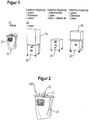
- FIG. 1 shows by reference numeral 10 a designated as the first part of the device part of the medical treatment arrangement in an embodiment of the invention. It is a filling and emptying station for filling and emptying a mobile trolley 20, which serves as a second device part.
- Reference numeral 30 represents the third device part, which in the exemplary embodiment illustrated here is designed as a dialysis machine for carrying out a dialysis treatment.
- a bag 21 which is designed with a 2D label 22, so that bag type and content are clearly identifiable.
- data is thus transferred from the bag to the filling station via a 2D matrix.
- reading or writing takes place between the trolley 20 and the filling station 10 in a unidirectional or bidirectional manner. Apart from this, it can also come to a charging, for example, a battery of the trolley 20 through the filling station 10.
- the trolley 20 can have, in addition to an energy store, a data memory and / or electronics for evaluating data.
- the energy store can be charged inductively by the filling station 10 as well as by the treatment device 30. It is also conceivable that energy is transferred from the energy store of the trolley 20 to the filling station 10 and / or to the treatment device 30.
- the filling station 10 and the treatment device 30 may preferably be made immobile or essentially immobile, in any case intended for a stationary use. Basically, however, the case is also covered by the invention that these units are movable, as is true for the trolley 20.
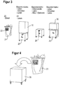
- FIG. 2 shows an enlarged view of the bag 21 of the trolley 20, which has the task of receiving fresh dialysis solutions from the filling station 10 and after the process to the treatment device 30, the solution to this or to make this available. Furthermore, the task may consist of receiving used dialysis fluid from the treatment device 30 and then releasing it to the filling station 10 again.
- filling station is to be understood broadly. It can affect both the filling process and the emptying process.
- Reference numeral 230 in accordance with FIG. 2 a breakable bag pin is marked.
- This pin is first broken when inserted into the treatment device 30 by a corresponding device in the treatment device 30 and thus marks a used bag.
- a marked bag is recognized by a corresponding sensor (eg optically or mechanically) when re-loading into the filling station and prevents refilling. This reliably prevents reuse.
- the measurement of the conductivity of the bag contents is provided.
- concentrates can be kept, which are solved in the filling with RO water in the filling station 10.
- a solution with a characteristic conductivity that changes as a result of use in the treatment device 30 by mass transfer, for example during a dialysis treatment is established.
- the filling station 10 checks the conductivity of the filled bag and, if the bag was not emptied in the filling station 10 after prior use and is forbidden to be reused, recognizes that concentrates which characteristically change the conductivity were not present in the bag. Thus, re-use is made and further action can be taken to prevent treatment with this reused bag.
- Such measures are, for example, emptying in the filling station 10, generating a warning or other alarm signal, the marking of the bag, etc.
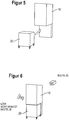
- FIG. 3 essentially shows FIG. 1 corresponding overview of the components of the medical treatment arrangement according to the invention, it being made clear here that in the embodiment shown here, both the data transmission and the transmission of energy are magnetoinductive.
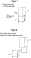
- FIG. 4 shows the step of upgrading the trolley 20 with a new bag 21. See this FIG. 5 shows, then the trolley 20 is connected to the filling station 10, in such a way that a fluid transfer and optionally a data and / or energy transfer is possible.
- FIG. 6 shows that the bag data and the trolley data are read and FIG. 7 shows the state that the bag has now been filled and the data, in particular data for filling the bag are also transmitted to the trolley 20 immediately.
- the information is transmitted to the trolley 20, that its tank or bag is filled and contains unused dialysis solution.
- the data transmitted between the device parts of the present invention may be any information, for example treatment data, patient data, device data, device component data, etc. It is conceivable, for example, that the information transmitted relates to the composition of the concentrates or the finished solution.
- FIG. 8 shows the state in which the connection between trolley 20 and filling station 10 has been disconnected.
- the trolley 20 has a display in which the data for the user are displayed visibly, which are stored in a storage unit of the trolley.
- This display may be, for example, an e-paper, which has the advantage that a reading of the data is possible even if the trolley 20 has no own power supply.
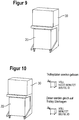
- the filled by means of the filling station 10 trolley 20 and the filled tank or bag of the trolley 20 is then moved with the trolley 20 to the treatment device 30 and connected to this, as can be seen from FIG. 9 evident.
- the trolley data are read out and data is also transferred to the trolley. If the data read out from the trolley 20 are in order, the treatment is released.
- the trolley 20 after completion of the treatment, bears the information that the bag is full and in use.
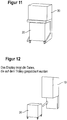
- FIG. 11 indicates the end of the treatment and the separation of the connection between the trolley 20 and the treatment device 30.
- the filled with the used dialysis fluid container of the trolley 20 is then moved with the trolley 20 back to the filling station 10, which serves in this case for emptying the tank (see. FIG. 12 ).
- the display of the trolley 20 shows the data stored on the trolley. This may be, for example, the data that has been transmitted from the treatment device 30 to the trolley 20.
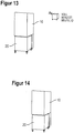
- FIG. 13 shows the state in which the Trolley stylist be read from the filling station 10. Subsequently, according to FIG. 14 the bag of the trolley 20 is emptied through the filling station 10.
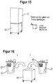
- FIG. 15 shows the state that the bag has been emptied and also these corresponding data are immediately transferred to the trolley 20. In this case, it is the information that the bag is empty and used.
- FIGS. 17 to 29 show a further embodiment, which differs from the first embodiment according to the FIGS. 1 to 16 only differs in that the bag is not executed with a 2D matrix as a means of identification, but with an RFID tag that is readable and writable.
- the bag is not executed with a 2D matrix as a means of identification, but with an RFID tag that is readable and writable.
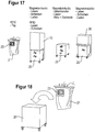
- the communication between filling station and trolley as well as between trolley and treatment unit is magneto-inductively, as is the case FIG. 17 evident.
- FIG. 18 shows the step of upgrading the trolley 20 with the new bag 21, which has an RFID tag 23 as a means of identification.
- FIG. 19 shows the step of the connection of the trolley 20, in which the bag 21 is inserted, with the filling station 10.
- the bag data of the bag of the trolley 20 are read by the filling station 10.
- the bag is then according to FIG. 20 filled by the filling station 10 and transferred the corresponding data equal to the RFID tag of the bag.
- FIG. 22 shows the connection of the trolley with filled tank with the treatment device 20.
- FIG. 23 concerns the release of the treatment.
- the bag data are read out and the data available after the treatment has been carried out by the treatment device 30 on the RFID tag of the bag.
- FIG. 24 indicates the end of the treatment and the connection between the trolley 20 and the treatment device 30 is disconnected.
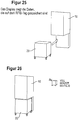
- the filled with the dialysis solution used trolley 20 is then moved to the filling station 10 (see. FIG. 25 ).
- the trolley 20 displays in its display the data stored on the RFID tag.
- FIG. 26 shows the reading of the bag data through the filling station 10 and FIG. 27 shows the process of bag emptying through the filling station 10.
- FIG. 28 shows a state in which the bag has been emptied and the data is immediately transferred to the bag RFID tag.
- FIGS. 30 to 43 show a third embodiment of the present invention, in which the bag for its identification has a 2D matrix and the communication between filling station and trolley and between trolley and treatment unit via RFID.
- the trolley 20 does not have its own energy store in this embodiment and the display of stored data takes place via an e-paper display.
- a use of a trolley with its own energy storage is also conceivable in this embodiment.
- E-paper and to write / read non-volatile memories eg EEPROM
- energy is needed once.
- the trolley 20 does not require its own energy storage in this embodiment.
- the trolley 20 is executed in this embodiment with an RFID tag 24 which is readable and writable. Data of the RFID tag can be displayed on the display of the trolley 20.
- RFID is used as the communication medium for communication between filling station and trolley and trolley and handling unit, and the bag 21 itself is implemented with a 2D Etticket or with a 2D matrix.
- the device parts correspond to the embodiment according to FIG. 1 , so that reference is made accordingly.
- FIG. 31 again shows the upgrading of the trolley 20 with a new bag 21
- FIG. 32 the connection with the filling station 10
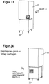
- FIG. 33 the reading of the bag data of the 2D-Ettickets, through the filling station 10th
- FIG. 34 shows the filling of the bag of the trolley 20 by the filling station 10. In this case, data is transferred to the trolley 20 and its memory.
- connection is then separated and the trolley shows on a run as an e-paper display the data stored in the trolley 20.
- the trolley 20 is moved to the treatment device 30 and connected thereto, as is known FIG. 36 evident.
- the treatment will be released.
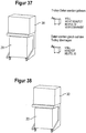
- the data relating to the treatment will then be transferred to the trolley immediately after treatment, as will be the case FIG. 37 evident.
- Figure 38 marks the end of the treatment. The connection between the treatment device 30 and the trolley 20 is disconnected.
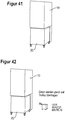
- FIG. 39 relates to the connection of the trolley 20 with the filling station 10. Again, the display shows the data that are now stored in the trolley 20.
- the trolley data are read out by means of the filling station 10 and according to FIG. 41 the bag is emptied.
Landscapes
- Health & Medical Sciences (AREA)
- Heart & Thoracic Surgery (AREA)
- Urology & Nephrology (AREA)
- Anesthesiology (AREA)
- Vascular Medicine (AREA)
- Engineering & Computer Science (AREA)
- Biomedical Technology (AREA)
- Hematology (AREA)
- Life Sciences & Earth Sciences (AREA)
- Animal Behavior & Ethology (AREA)
- General Health & Medical Sciences (AREA)
- Public Health (AREA)
- Veterinary Medicine (AREA)
- Emergency Medicine (AREA)
- External Artificial Organs (AREA)
Claims (14)
- Système de traitement médical comportant au moins trois éléments d'appareil, le premier élément d'appareil (10) étant une station de remplissage et/ou de vidage qui n'est pas conçue pour le traitement d'un patient, le deuxième élément d'appareil (20) possédant sa propre source d'approvisionnement énergétique et est conçue de manière mobile et comporte des roulettes de manière à pouvoir être déplacé par rapport au premier élément d'appareil (10) et par rapport à un troisième élément d'appareil (30), et le troisième élément d'appareil étant une station de traitement,
caractérisé en ce que
le deuxième élément d'appareil (20) est conçu en liaison avec le troisième élément d'appareil (30) de telle sorte qu'il est possible de procéder avec ceux-ci à un procédé de dialyse, en ce que des poche ou d'autres récipients sont placés sous forme de produits jetable dans le deuxième élément d'appareil (20) et en ce que le premier élément d'appareil (10) et le deuxième élément d'appareil (20) et/ou le deuxième élément d'appareil (20) et le troisième élément d'appareil (30) sont réalisés de manière à ce qu'il soit possible d'échanger des données entre ceux-ci de manière unidirectionnelle ou bidirectionnelle, le deuxième élément d'appareil (20) comportant une mémoire dans laquelle on mémorise des données de traitement concernant le traitement du patient et/ou des données concernant la poche ou d'autres récipients insérés dans le deuxième élément d'appareil (20) et/ou le troisième élément d'appareil (30). - Système de traitement médical selon la revendication 1, caractérisé en ce que le premier élément d'appareil (10) et/ou le troisième élément d'appareil (30) est ou sont conçus comme des éléments immobiles ou en grande partie immobiles.
- Système de traitement médical selon la revendication 1 ou 2, caractérisé en ce que le procédé de dialyse est une hémodialyse ou une dialyse péritonéale.
- Système de traitement médical selon l'une quelconque des revendications précédentes, caractérisé en ce qu'au moins l'un des éléments d'appareil - de préférence plusieurs ou tous les éléments d'appareil du système de traitement médical - est conçu de telle sorte que les transmissions de données et/ou de l'énergie sont effectuées sans fil ou avec fil entre deux éléments d'appareil.
- Système de traitement médical selon la revendication 4, caractérisé en ce qu'au moins l'un des éléments d'appareil - de préférence plusieurs ou tous les éléments d'appareil - est ou sont conçu(s) de telle sorte que la transmission de données et d'énergie a lieu simultanément et/ou au moyen du même dispositif.
- Système de traitement médical selon l'une quelconque des revendications précédentes, caractérisé en ce que le deuxième élément d'appareil (20) possède une ou plusieurs mémoires non-volatiles pour le stockage de données.
- Système de traitement médical selon l'une quelconque des revendications précédentes, caractérisé en ce que l'approvisionnement énergétique du deuxième élément d'appareil (20) est conçue de telle sorte qu'elle permet, en cas de panne de l'approvisionnement énergétique du premier élément d'appareil (10) ou du troisième élément d'appareil (30), d'effectuer un approvisionnement énergétique de secours pour le premier élément d'appareil (10) ou le troisième élément d'appareil (30) au moyen du deuxième élément d'appareil (20).
- Système de traitement médical selon l'une quelconque des revendications précédentes, caractérisé en ce que des moyens sont prévus qui sont conçus de telle sorte que des données stockées dans le deuxième élément d'appareil (20) sont transmises à celui-ci ou reçues par celui-ci en approchant le premier élément d'appareil (10) et/ou le troisième élément d'appareil (30).
- Système de traitement médical selon l'une quelconque des revendications précédentes, caractérisé en ce que des moyens de contrôle sont prévus qui sont conçus de telle sorte que les données transmises au côté du deuxième élément d'appareil (20) au premier élément d'appareil (10) ou au troisième élément d'appareil (30) sont soumises à un contrôle, dans lequel il est de préférence prévu, que des moyens de décision sont prévus qui sont conçus de telle sorte, qu'une décision est faite à l'aide du résultat de contrôle effectué dans les moyens de contrôle, si un traitement à l'aide du résultat du contrôle est effectué dans les moyens de contrôle ou pas.
- Système de traitement médical selon l'une quelconque des revendications précédentes, caractérisé en ce que le matériel jetable est doté de marquages lisibles, dans lequel il est de préférence prévu que le marquage est une matrice en deux dimensions, un code à barres ou une étiquette RFID.
- Système de traitement médical selon l'une quelconque des revendications précédentes, caractérisé en ce que le premier élément d'appareil (10) et/ou le deuxième élément d'appareil (20) et/ou le troisième élément d'appareil (30) est doté d'identifiants, de préférence des étiquettes électroniques, au moyen desquels les éléments d'appareil eux-mêmes et/ou l'appartenance d'un élément d'appareil à un autre élément d'appareil peuvent être identifiés.
- Système de traitement médical selon l'une quelconque des revendications précédentes, caractérisé en ce que le premier élément d'appareil (10) et/ou le deuxième élément d'appareil (20) et/ou le troisième élément d'appareil (30) est ou sont dotés d'un ou de plusieurs dispositifs d'affichage et/ou de saisie, en particulier d'affichages, dans lequel il est de préférence prévu que l'affichages est un écran TFT (LCD), OLED ou papier électronique.
- Système de traitement médical selon l'une quelconque des revendications précédentes, caractérisé en ce que le deuxième élément d'appareil (20) est doté d'au moins un réservoir pour recueillir un liquide de traitement frais et/ou usé et/ou un liquide de substitution.
- Système de traitement médical selon la revendication 13, caractérisé en ce que le premier élément d'appareil (10) et/ou le troisième élément d'appareil (30) dispos(ent) de moyens à l'aide desquels le réservoir du deuxième élément d'appareil (20) peut être rempli et/ou vidé.
Applications Claiming Priority (2)
| Application Number | Priority Date | Filing Date | Title |
|---|---|---|---|
| DE102010022201A DE102010022201A1 (de) | 2010-05-20 | 2010-05-20 | Medizinische Behandlungsanordnung |
| PCT/EP2011/002532 WO2011144355A1 (fr) | 2010-05-20 | 2011-05-20 | Système de traitement médical |
Publications (2)
| Publication Number | Publication Date |
|---|---|
| EP2571547A1 EP2571547A1 (fr) | 2013-03-27 |
| EP2571547B1 true EP2571547B1 (fr) | 2019-03-27 |
Family
ID=44501810
Family Applications (1)
| Application Number | Title | Priority Date | Filing Date |
|---|---|---|---|
| EP11720729.0A Active EP2571547B1 (fr) | 2010-05-20 | 2011-05-20 | Système de traitement médical |
Country Status (6)
| Country | Link |
|---|---|
| US (1) | US9511182B2 (fr) |
| EP (1) | EP2571547B1 (fr) |
| JP (1) | JP5973424B2 (fr) |
| CN (1) | CN103037917B (fr) |
| DE (1) | DE102010022201A1 (fr) |
| WO (1) | WO2011144355A1 (fr) |
Families Citing this family (64)
| Publication number | Priority date | Publication date | Assignee | Title |
|---|---|---|---|---|
| ATE505223T1 (de) | 2002-07-19 | 2011-04-15 | Baxter Int | System für die peritonealdialyse |
| US7736328B2 (en) | 2007-07-05 | 2010-06-15 | Baxter International Inc. | Dialysis system having supply container autoconnection |
| US10973968B2 (en) | 2008-02-14 | 2021-04-13 | Baxter International Inc. | Control of a water device via a dialysis machine user interface |
| US8057679B2 (en) | 2008-07-09 | 2011-11-15 | Baxter International Inc. | Dialysis system having trending and alert generation |
| US10089443B2 (en) | 2012-05-15 | 2018-10-02 | Baxter International Inc. | Home medical device systems and methods for therapy prescription and tracking, servicing and inventory |
| US9399091B2 (en) | 2009-09-30 | 2016-07-26 | Medtronic, Inc. | System and method to regulate ultrafiltration |
| JP2014500538A (ja) | 2010-10-12 | 2014-01-09 | タニス,ケヴィン ジェイ. | 医療機器 |
| US9750862B2 (en) | 2011-04-29 | 2017-09-05 | Medtronic, Inc. | Adaptive system for blood fluid removal |
| DE102012005194B4 (de) * | 2012-03-16 | 2025-10-30 | Fresenius Medical Care Deutschland Gmbh | Medizinisches Behandlungssystem |
| US10010663B2 (en) | 2013-02-01 | 2018-07-03 | Medtronic, Inc. | Fluid circuit for delivery of renal replacement therapies |
| US9623164B2 (en) | 2013-02-01 | 2017-04-18 | Medtronic, Inc. | Systems and methods for multifunctional volumetric fluid control |
| US10850016B2 (en) | 2013-02-01 | 2020-12-01 | Medtronic, Inc. | Modular fluid therapy system having jumpered flow paths and systems and methods for cleaning and disinfection |
| RU2015143724A (ru) | 2013-03-14 | 2017-04-17 | Смит Энд Нефью Инк. | Системы и способы применения терапии с использованием пониженного давления |
| US9737649B2 (en) | 2013-03-14 | 2017-08-22 | Smith & Nephew, Inc. | Systems and methods for applying reduced pressure therapy |
| JP6679483B2 (ja) | 2013-08-13 | 2020-04-15 | スミス アンド ネフュー インコーポレイテッド | 減圧治療を実施するためのシステムおよび方法 |
| CN105848581B (zh) | 2013-11-04 | 2019-01-01 | 美敦力公司 | 用于管理身体中的体液体积的方法和装置 |
| US9764073B2 (en) | 2014-02-26 | 2017-09-19 | Medtronic, Inc. | Authentication and tracking system |
| US9764076B2 (en) | 2014-02-26 | 2017-09-19 | Medtronic, Inc. | Authentication system utilized in a sorbent-based dialysis system for therapy optimization |
| US9248221B2 (en) | 2014-04-08 | 2016-02-02 | Incuvate, Llc | Aspiration monitoring system and method |
| US12133789B2 (en) | 2014-07-31 | 2024-11-05 | Smith & Nephew, Inc. | Reduced pressure therapy apparatus construction and control |
| US10744239B2 (en) | 2014-07-31 | 2020-08-18 | Smith & Nephew, Inc. | Leak detection in negative pressure wound therapy system |
| US9713665B2 (en) | 2014-12-10 | 2017-07-25 | Medtronic, Inc. | Degassing system for dialysis |
| US10874787B2 (en) | 2014-12-10 | 2020-12-29 | Medtronic, Inc. | Degassing system for dialysis |
| CN107106743B (zh) | 2014-12-30 | 2020-06-05 | 史密夫和内修有限公司 | 用于应用减压治疗的系统和方法 |
| CN107106742B (zh) | 2014-12-30 | 2020-12-15 | 史密夫和内修有限公司 | 用于应用减压治疗的系统和方法 |
| DE102015103945A1 (de) * | 2015-03-17 | 2016-09-22 | Förster Technik GmbH | Verfahren zum Dokumentieren von Behandlungen von Lebewesen |
| EP3314488B1 (fr) | 2015-06-25 | 2024-03-13 | Gambro Lundia AB | Système et procédé de dispositif médical comprenant une base de données distribuée |
| US10980930B2 (en) | 2015-07-24 | 2021-04-20 | Medtronic, Inc | Fluid connectors and fluid flow paths for an infusate caddy |
| WO2017019635A1 (fr) | 2015-07-24 | 2017-02-02 | Medtronic, Inc. | Étapes d'amorçage de dialyse au moyen d'un chariot de perfusat |
| US11103626B2 (en) | 2015-07-24 | 2021-08-31 | Medtronic, Inc. | Infusate holder |
| US10874788B2 (en) * | 2015-07-24 | 2020-12-29 | Medtronic, Inc. | Infusate caddy for a dialysis system |
| CN108025124A (zh) * | 2015-08-27 | 2018-05-11 | 美敦力公司 | 在基于吸附剂的透析系统中使用进行治疗优化的认证系统 |
| US10702292B2 (en) | 2015-08-28 | 2020-07-07 | Incuvate, Llc | Aspiration monitoring system and method |
| WO2017062042A1 (fr) | 2015-10-07 | 2017-04-13 | Smith & Nephew, Inc. | Systèmes et procédés d'application de traitement à pression réduite |
| US10226263B2 (en) | 2015-12-23 | 2019-03-12 | Incuvate, Llc | Aspiration monitoring system and method |
| JP2019508124A (ja) | 2016-02-12 | 2019-03-28 | スミス アンド ネフュー インコーポレイテッド | 減圧療法の動作条件を検出するシステムおよび方法 |
| DE102016001868A1 (de) * | 2016-02-17 | 2017-08-17 | Fresenius Medical Care Deutschland Gmbh | Medizinisches Gerät und Verfahren zum Betreiben eines medizinischen Gerätes |
| US10994064B2 (en) | 2016-08-10 | 2021-05-04 | Medtronic, Inc. | Peritoneal dialysate flow path sensing |
| US10874790B2 (en) | 2016-08-10 | 2020-12-29 | Medtronic, Inc. | Peritoneal dialysis intracycle osmotic agent adjustment |
| US12329892B2 (en) | 2016-04-04 | 2025-06-17 | Mozarc Medical Us Llc | Dextrose concentration sensor for a peritoneal dialysis system |
| EP3439711A1 (fr) | 2016-04-04 | 2019-02-13 | Medtronic Inc. | Système de génération de fluide de dialysat péritonéal |
| CA3280035A1 (en) | 2016-05-06 | 2025-10-30 | Gambro Lundia Ab | Systems and methods for peritoneal dialysis having point of use dialysis fluid preparation including mixing and heating therefor |
| AU2017261814B2 (en) | 2016-05-13 | 2022-05-19 | Smith & Nephew, Inc. | Automatic wound coupling detection in negative pressure wound therapy systems |
| US11013843B2 (en) | 2016-09-09 | 2021-05-25 | Medtronic, Inc. | Peritoneal dialysis fluid testing system |
| KR102476516B1 (ko) | 2016-12-21 | 2022-12-09 | 감브로 룬디아 아베 | 외부 도메인을 지원하는 안전한 클러스터 도메인을 구비한 정보 기술 인프라를 포함하는 의료 장치 시스템 |
| US11116657B2 (en) | 2017-02-02 | 2021-09-14 | Zoll Circulation, Inc. | Devices, systems and methods for endovascular temperature control |
| US11185440B2 (en) * | 2017-02-02 | 2021-11-30 | Zoll Circulation, Inc. | Devices, systems and methods for endovascular temperature control |
| US10561779B2 (en) | 2017-05-12 | 2020-02-18 | Medtronic, Inc. | Infusate containers |
| US10493192B2 (en) | 2017-05-12 | 2019-12-03 | Medtronic, Inc. | Infusate sleeve |
| US11278654B2 (en) | 2017-12-07 | 2022-03-22 | Medtronic, Inc. | Pneumatic manifold for a dialysis system |
| JP6978951B2 (ja) | 2018-01-24 | 2021-12-08 | 日機装株式会社 | 透析用ベースユニット及び透析システム |
| US11033667B2 (en) | 2018-02-02 | 2021-06-15 | Medtronic, Inc. | Sorbent manifold for a dialysis system |
| DE102018103940A1 (de) * | 2018-02-21 | 2019-08-22 | Fresenius Medical Care Deutschland Gmbh | Transportbehälter |
| US11110215B2 (en) | 2018-02-23 | 2021-09-07 | Medtronic, Inc. | Degasser and vent manifolds for dialysis |
| US11806457B2 (en) | 2018-11-16 | 2023-11-07 | Mozarc Medical Us Llc | Peritoneal dialysis adequacy meaurements |
| US11806456B2 (en) | 2018-12-10 | 2023-11-07 | Mozarc Medical Us Llc | Precision peritoneal dialysis therapy based on dialysis adequacy measurements |
| US12433976B2 (en) | 2019-01-08 | 2025-10-07 | Mozarc Medical Us Llc | Bicarbonate sensor for dialysis |
| DE102019129933A1 (de) * | 2019-11-06 | 2021-05-06 | Fresenius Medical Care Deutschland Gmbh | Beutelhalter, System und Verfahren zum Entleeren eines Effluentbeutels |
| DE102019129934B4 (de) * | 2019-11-06 | 2024-05-16 | Fresenius Medical Care Deutschland Gmbh | Beutel, System und Verfahren zum Entleeren eines Effluentbeutels |
| US12128165B2 (en) | 2020-04-27 | 2024-10-29 | Mozarc Medical Us Llc | Dual stage degasser |
| US12154673B2 (en) | 2021-08-02 | 2024-11-26 | Mozarc Medical Us Llc | Artificial intelligence assisted home therapy settings for dialysis |
| US11850344B2 (en) | 2021-08-11 | 2023-12-26 | Mozarc Medical Us Llc | Gas bubble sensor |
| US11965763B2 (en) | 2021-11-12 | 2024-04-23 | Mozarc Medical Us Llc | Determining fluid flow across rotary pump |
| US11944733B2 (en) | 2021-11-18 | 2024-04-02 | Mozarc Medical Us Llc | Sodium and bicarbonate control |
Citations (4)
| Publication number | Priority date | Publication date | Assignee | Title |
|---|---|---|---|---|
| EP0004600A2 (fr) * | 1978-03-22 | 1979-10-17 | Hoechst Aktiengesellschaft | Pompe péristaltique pour solution de dialysat |
| US5762782A (en) * | 1995-02-13 | 1998-06-09 | Aksys, Ltd. | Water treatment for dialysate preparation |
| US20070135779A1 (en) * | 2005-12-14 | 2007-06-14 | Stryker Corporation | Medical/surgical waste collection and disposal system including waste containers of different storage volumes with inter-container transfer valve and independently controlled vacuum levels |
| US20080230450A1 (en) * | 2005-01-07 | 2008-09-25 | Burbank Jeffrey H | Filtration System for Preparation of Fluids for Medical Applications |
Family Cites Families (31)
| Publication number | Priority date | Publication date | Assignee | Title |
|---|---|---|---|---|
| AT282966B (de) | 1968-10-25 | 1970-07-27 | Basf Ag | Verfahren zur Herstellung hochmolekularer linearer Polyester |
| FR2493706A1 (fr) | 1980-11-13 | 1982-05-14 | Hospal Sodip | Rein artificiel avec circuit de liquide de dialyse integre |
| AU570100B2 (en) | 1984-03-19 | 1988-03-03 | Gambro Pty Limited | Dialysis system having reservior with 2 compartments |
| DE9302790U1 (de) | 1993-02-26 | 1994-06-23 | NephroTec Medizinische Geräte GmbH, 42287 Wuppertal | Hilfsgerät zur Verwendung bei einem Bikarbonat-Hämodialyseverfahren |
| JPH1085322A (ja) * | 1996-07-26 | 1998-04-07 | San Medical Gijutsu Kenkyusho:Kk | 人工心臓の可搬駆動システム |
| US5914047A (en) | 1997-06-30 | 1999-06-22 | Grifco, Llc | On-site biohazardous liquid medical waste collection and treatment system and method of using such system |
| DE19858158C2 (de) | 1998-12-16 | 2002-04-18 | Holger Panitzek | Einer Transportvorrichtung zugeordnetes Lesesystem |
| DE19905937C1 (de) * | 1999-02-12 | 2000-07-13 | Karsten Kirchhof | Mobile Herz-Lungen-Maschine |
| US7645258B2 (en) * | 1999-12-01 | 2010-01-12 | B. Braun Medical, Inc. | Patient medication IV delivery pump with wireless communication to a hospital information management system |
| AU2001237688A1 (en) | 2000-02-28 | 2001-09-12 | Valemont Participation Corp. | Method and system for hemodialysis for use in a non-clinical environment |
| CZ20023818A3 (cs) * | 2000-05-18 | 2003-06-18 | Alaris Meidical Systems, Inc. | Systém a způsob pro správu informací týkajících se poskytování lékařské péče |
| US6894456B2 (en) * | 2001-11-07 | 2005-05-17 | Quallion Llc | Implantable medical power module |
| US7747311B2 (en) | 2002-03-06 | 2010-06-29 | Mako Surgical Corp. | System and method for interactive haptic positioning of a medical device |
| ATE484301T1 (de) * | 2002-08-08 | 2010-10-15 | Asahi Kasei Kuraray Medical Co | Blutreinigungsvorrichtung |
| EP1592494B1 (fr) * | 2003-01-07 | 2009-06-24 | NxStage Medical, Inc. | Systeme de filtration discontinue destine a la preparation d'un liquide de remplacement sterile pour la therapie renale |
| SE0302698L (sv) * | 2003-10-13 | 2005-04-14 | Gambro Lundia Ab | Anordning för genomförande av en peritonealdialys -behandling |
| CA2556566A1 (fr) * | 2004-02-17 | 2006-02-23 | Stryker Instruments | Unite de collecte de dechets |
| DE602006016955D1 (de) * | 2005-04-06 | 2010-10-28 | Mallinckrodt Inc | Systeme und Verfahren zur Verwaltung von Informationen bezüglich medizinischer Flüssigkeiten und Behälter dafür |
| US7713240B2 (en) * | 2005-09-13 | 2010-05-11 | Medtronic Minimed, Inc. | Modular external infusion device |
| US20070093697A1 (en) | 2005-10-21 | 2007-04-26 | Theranova, Llc | Method and apparatus for detection of right to left shunting in the cardiopulmonary vasculature |
| JP2008104737A (ja) * | 2006-10-26 | 2008-05-08 | Terumo Corp | 腹膜透析装置 |
| WO2008082033A1 (fr) | 2006-12-28 | 2008-07-10 | Jsm Healthcare Inc | Système de production et de distribution de concentré pour l'hémodialyse |
| WO2008099384A2 (fr) * | 2007-02-13 | 2008-08-21 | Modu Ltd. | Appareil de communication sans fil modulaire |
| DE102007009269B4 (de) | 2007-02-26 | 2010-11-11 | Fresenius Medical Care Deutschland Gmbh | Vorrichtung und Verfahren zum Befüllen und/oder Entleeren eines Dialysegerätes |
| US8934984B2 (en) * | 2007-05-31 | 2015-01-13 | Cochlear Limited | Behind-the-ear (BTE) prosthetic device with antenna |
| US8496609B2 (en) * | 2007-07-05 | 2013-07-30 | Baxter International Inc. | Fluid delivery system with spiked cassette |
| US8141417B2 (en) | 2007-08-23 | 2012-03-27 | Mallinckrodt Llc | Syringe content detection using RF energy |
| US7879026B2 (en) * | 2007-09-07 | 2011-02-01 | Asante Solutions, Inc. | Controlled adjustment of medicine dispensation from an infusion pump device |
| DE102008050849A1 (de) * | 2008-10-08 | 2010-04-15 | Fresenius Medical Care Deutschland Gmbh | Vorrichtung zur Umkehr des Blutflusses für eine extrakorporale Blutbehandlungsvorrichtung und Verfahren zur Feststellung der Umkehr des Blutflusses bei einer extrakorporalen Blutbehandlung |
| WO2010091364A1 (fr) * | 2009-02-06 | 2010-08-12 | Velomedix, Inc. | Procédé et appareil d'induction d'hypothermie thérapeutique |
| DE102010011465A1 (de) | 2010-03-15 | 2011-09-15 | Fresenius Medical Care Deutschland Gmbh | System zur Durchführung einer Blutbehandlung |
-
2010
- 2010-05-20 DE DE102010022201A patent/DE102010022201A1/de not_active Ceased
-
2011
- 2011-05-20 EP EP11720729.0A patent/EP2571547B1/fr active Active
- 2011-05-20 JP JP2013510526A patent/JP5973424B2/ja active Active
- 2011-05-20 CN CN201180025072.6A patent/CN103037917B/zh active Active
- 2011-05-20 US US13/699,110 patent/US9511182B2/en active Active
- 2011-05-20 WO PCT/EP2011/002532 patent/WO2011144355A1/fr not_active Ceased
Patent Citations (4)
| Publication number | Priority date | Publication date | Assignee | Title |
|---|---|---|---|---|
| EP0004600A2 (fr) * | 1978-03-22 | 1979-10-17 | Hoechst Aktiengesellschaft | Pompe péristaltique pour solution de dialysat |
| US5762782A (en) * | 1995-02-13 | 1998-06-09 | Aksys, Ltd. | Water treatment for dialysate preparation |
| US20080230450A1 (en) * | 2005-01-07 | 2008-09-25 | Burbank Jeffrey H | Filtration System for Preparation of Fluids for Medical Applications |
| US20070135779A1 (en) * | 2005-12-14 | 2007-06-14 | Stryker Corporation | Medical/surgical waste collection and disposal system including waste containers of different storage volumes with inter-container transfer valve and independently controlled vacuum levels |
Also Published As
| Publication number | Publication date |
|---|---|
| JP5973424B2 (ja) | 2016-08-23 |
| CN103037917B (zh) | 2016-11-16 |
| JP2013526354A (ja) | 2013-06-24 |
| DE102010022201A1 (de) | 2011-11-24 |
| EP2571547A1 (fr) | 2013-03-27 |
| US9511182B2 (en) | 2016-12-06 |
| WO2011144355A1 (fr) | 2011-11-24 |
| US20130062265A1 (en) | 2013-03-14 |
| CN103037917A (zh) | 2013-04-10 |
Similar Documents
| Publication | Publication Date | Title |
|---|---|---|
| EP2571547B1 (fr) | Système de traitement médical | |
| EP2913431B2 (fr) | Système de détection de la consommation d'un fluide dans une installation de nettoyage ou de lavage | |
| DE102007050012B4 (de) | Etikettieranlage und Vorrichtung zum Verifizieren | |
| EP1118042A1 (fr) | Systeme d'impression ou de reproduction comportant un recipient reutilisable pour les matieres consommables et procede pour utiliser ledit procede | |
| EP2649592B1 (fr) | Cassette pour argent avec cachet électronique | |
| WO2010052002A1 (fr) | Système de dosage et procédé de dosage d’un fluide | |
| DE102009037315A1 (de) | Vorrichtung zur Aufnahme von zu entsorgenden Gegenständen für einen Operationssaal | |
| EP3634190B1 (fr) | Système distributeur de milieux liquides | |
| DE202017101233U1 (de) | Vorrichtung zum Identifizieren von Objekten, Erfassen von Daten und Kontrollieren von Arbeitsprozessen, System zur Kontrolle logistischer Prozesse | |
| DE102011076135A1 (de) | Verfahren und Vorrichtung zur Kommunikation mittels eines Transformators | |
| DE102011003777A1 (de) | Aufladbare RFID-Sonde und Ladestation zum Aufladen der RFID-Sonde | |
| BE1032876B1 (de) | Lagerbehälter zum Lagern von Lebensmitteln, Verfahren und Vorrichtung zum Betreiben eines Lagerbehälters und System | |
| EP3555354B1 (fr) | Dispositif et procédé de manipulation de débris d'une aiguille cassée | |
| DE102009008917A1 (de) | Verfahren zur Zurverfügungstellung und Wiederaufbereitung eines medizinischen Produkts, medizinisches Produkt sowie System zur Durchführung des Verfahrens | |
| EP3252440A1 (fr) | Procédé de fonctionnement d'un compteur pour un fluide, compteur et système compteur | |
| DE102018132421B4 (de) | Handsender zur fernsteuerbaren Auslösung eines technischen Ereignisses, insbesondere Zutrittsbuchung, Zeitbuchung oder Türöffnung | |
| DE202014006533U1 (de) | Elektronischer Kennzeichnungsträger, Schreib- und/oder Lesegerät sowie Kennzeichnungssystem | |
| DE102019121491A1 (de) | Informations- und Lokalisierungssystem | |
| EP4584736A1 (fr) | Procédé de détermination automatique de données de consommation de contenu multimédia dans une ligne de remplissage et dispositif de mise en oeuvre du procédé | |
| WO2008011847A1 (fr) | Appareil d'affichage | |
| DE102021114319A1 (de) | Nachfüllstation für Spenderdose mit Transponder-Lesegerät und Spenderdose-Transponder | |
| DE102018103940A1 (de) | Transportbehälter |
Legal Events
| Date | Code | Title | Description |
|---|---|---|---|
| PUAI | Public reference made under article 153(3) epc to a published international application that has entered the european phase |
Free format text: ORIGINAL CODE: 0009012 |
|
| 17P | Request for examination filed |
Effective date: 20121214 |
|
| AK | Designated contracting states |
Kind code of ref document: A1 Designated state(s): AL AT BE BG CH CY CZ DE DK EE ES FI FR GB GR HR HU IE IS IT LI LT LU LV MC MK MT NL NO PL PT RO RS SE SI SK SM TR |
|
| DAX | Request for extension of the european patent (deleted) | ||
| 17Q | First examination report despatched |
Effective date: 20160329 |
|
| GRAP | Despatch of communication of intention to grant a patent |
Free format text: ORIGINAL CODE: EPIDOSNIGR1 |
|
| STAA | Information on the status of an ep patent application or granted ep patent |
Free format text: STATUS: GRANT OF PATENT IS INTENDED |
|
| INTG | Intention to grant announced |
Effective date: 20181009 |
|
| GRAS | Grant fee paid |
Free format text: ORIGINAL CODE: EPIDOSNIGR3 |
|
| GRAA | (expected) grant |
Free format text: ORIGINAL CODE: 0009210 |
|
| STAA | Information on the status of an ep patent application or granted ep patent |
Free format text: STATUS: THE PATENT HAS BEEN GRANTED |
|
| AK | Designated contracting states |
Kind code of ref document: B1 Designated state(s): AL AT BE BG CH CY CZ DE DK EE ES FI FR GB GR HR HU IE IS IT LI LT LU LV MC MK MT NL NO PL PT RO RS SE SI SK SM TR |
|
| REG | Reference to a national code |
Ref country code: GB Ref legal event code: FG4D Free format text: NOT ENGLISH |
|
| RIN1 | Information on inventor provided before grant (corrected) |
Inventor name: SAUER, KLAUS Inventor name: NIKOLIC, DEJAN Inventor name: BALSCHAT, KLAUS Inventor name: HEIDE, ALEXANDER Inventor name: HARTMANN, MARCUS Inventor name: BREITKOPF, BERTHOLD |
|
| REG | Reference to a national code |
Ref country code: CH Ref legal event code: EP |
|
| REG | Reference to a national code |
Ref country code: DE Ref legal event code: R096 Ref document number: 502011015534 Country of ref document: DE |
|
| REG | Reference to a national code |
Ref country code: AT Ref legal event code: REF Ref document number: 1112268 Country of ref document: AT Kind code of ref document: T Effective date: 20190415 |
|
| REG | Reference to a national code |
Ref country code: IE Ref legal event code: FG4D Free format text: LANGUAGE OF EP DOCUMENT: GERMAN |
|
| REG | Reference to a national code |
Ref country code: SE Ref legal event code: TRGR |
|
| PG25 | Lapsed in a contracting state [announced via postgrant information from national office to epo] |
Ref country code: LT Free format text: LAPSE BECAUSE OF FAILURE TO SUBMIT A TRANSLATION OF THE DESCRIPTION OR TO PAY THE FEE WITHIN THE PRESCRIBED TIME-LIMIT Effective date: 20190327 Ref country code: FI Free format text: LAPSE BECAUSE OF FAILURE TO SUBMIT A TRANSLATION OF THE DESCRIPTION OR TO PAY THE FEE WITHIN THE PRESCRIBED TIME-LIMIT Effective date: 20190327 Ref country code: NO Free format text: LAPSE BECAUSE OF FAILURE TO SUBMIT A TRANSLATION OF THE DESCRIPTION OR TO PAY THE FEE WITHIN THE PRESCRIBED TIME-LIMIT Effective date: 20190627 |
|
| REG | Reference to a national code |
Ref country code: NL Ref legal event code: MP Effective date: 20190327 |
|
| PG25 | Lapsed in a contracting state [announced via postgrant information from national office to epo] |
Ref country code: NL Free format text: LAPSE BECAUSE OF FAILURE TO SUBMIT A TRANSLATION OF THE DESCRIPTION OR TO PAY THE FEE WITHIN THE PRESCRIBED TIME-LIMIT Effective date: 20190327 Ref country code: GR Free format text: LAPSE BECAUSE OF FAILURE TO SUBMIT A TRANSLATION OF THE DESCRIPTION OR TO PAY THE FEE WITHIN THE PRESCRIBED TIME-LIMIT Effective date: 20190628 Ref country code: BG Free format text: LAPSE BECAUSE OF FAILURE TO SUBMIT A TRANSLATION OF THE DESCRIPTION OR TO PAY THE FEE WITHIN THE PRESCRIBED TIME-LIMIT Effective date: 20190627 Ref country code: HR Free format text: LAPSE BECAUSE OF FAILURE TO SUBMIT A TRANSLATION OF THE DESCRIPTION OR TO PAY THE FEE WITHIN THE PRESCRIBED TIME-LIMIT Effective date: 20190327 Ref country code: LV Free format text: LAPSE BECAUSE OF FAILURE TO SUBMIT A TRANSLATION OF THE DESCRIPTION OR TO PAY THE FEE WITHIN THE PRESCRIBED TIME-LIMIT Effective date: 20190327 Ref country code: RS Free format text: LAPSE BECAUSE OF FAILURE TO SUBMIT A TRANSLATION OF THE DESCRIPTION OR TO PAY THE FEE WITHIN THE PRESCRIBED TIME-LIMIT Effective date: 20190327 |
|
| PG25 | Lapsed in a contracting state [announced via postgrant information from national office to epo] |
Ref country code: ES Free format text: LAPSE BECAUSE OF FAILURE TO SUBMIT A TRANSLATION OF THE DESCRIPTION OR TO PAY THE FEE WITHIN THE PRESCRIBED TIME-LIMIT Effective date: 20190327 Ref country code: PT Free format text: LAPSE BECAUSE OF FAILURE TO SUBMIT A TRANSLATION OF THE DESCRIPTION OR TO PAY THE FEE WITHIN THE PRESCRIBED TIME-LIMIT Effective date: 20190727 Ref country code: AL Free format text: LAPSE BECAUSE OF FAILURE TO SUBMIT A TRANSLATION OF THE DESCRIPTION OR TO PAY THE FEE WITHIN THE PRESCRIBED TIME-LIMIT Effective date: 20190327 Ref country code: EE Free format text: LAPSE BECAUSE OF FAILURE TO SUBMIT A TRANSLATION OF THE DESCRIPTION OR TO PAY THE FEE WITHIN THE PRESCRIBED TIME-LIMIT Effective date: 20190327 Ref country code: CZ Free format text: LAPSE BECAUSE OF FAILURE TO SUBMIT A TRANSLATION OF THE DESCRIPTION OR TO PAY THE FEE WITHIN THE PRESCRIBED TIME-LIMIT Effective date: 20190327 Ref country code: SK Free format text: LAPSE BECAUSE OF FAILURE TO SUBMIT A TRANSLATION OF THE DESCRIPTION OR TO PAY THE FEE WITHIN THE PRESCRIBED TIME-LIMIT Effective date: 20190327 Ref country code: RO Free format text: LAPSE BECAUSE OF FAILURE TO SUBMIT A TRANSLATION OF THE DESCRIPTION OR TO PAY THE FEE WITHIN THE PRESCRIBED TIME-LIMIT Effective date: 20190327 |
|
| PG25 | Lapsed in a contracting state [announced via postgrant information from national office to epo] |
Ref country code: PL Free format text: LAPSE BECAUSE OF FAILURE TO SUBMIT A TRANSLATION OF THE DESCRIPTION OR TO PAY THE FEE WITHIN THE PRESCRIBED TIME-LIMIT Effective date: 20190327 Ref country code: SM Free format text: LAPSE BECAUSE OF FAILURE TO SUBMIT A TRANSLATION OF THE DESCRIPTION OR TO PAY THE FEE WITHIN THE PRESCRIBED TIME-LIMIT Effective date: 20190327 |
|
| REG | Reference to a national code |
Ref country code: CH Ref legal event code: PL |
|
| PG25 | Lapsed in a contracting state [announced via postgrant information from national office to epo] |
Ref country code: IS Free format text: LAPSE BECAUSE OF FAILURE TO SUBMIT A TRANSLATION OF THE DESCRIPTION OR TO PAY THE FEE WITHIN THE PRESCRIBED TIME-LIMIT Effective date: 20190727 |
|
| REG | Reference to a national code |
Ref country code: DE Ref legal event code: R097 Ref document number: 502011015534 Country of ref document: DE |
|
| PG25 | Lapsed in a contracting state [announced via postgrant information from national office to epo] |
Ref country code: LI Free format text: LAPSE BECAUSE OF NON-PAYMENT OF DUE FEES Effective date: 20190531 Ref country code: DK Free format text: LAPSE BECAUSE OF FAILURE TO SUBMIT A TRANSLATION OF THE DESCRIPTION OR TO PAY THE FEE WITHIN THE PRESCRIBED TIME-LIMIT Effective date: 20190327 Ref country code: CH Free format text: LAPSE BECAUSE OF NON-PAYMENT OF DUE FEES Effective date: 20190531 Ref country code: MC Free format text: LAPSE BECAUSE OF FAILURE TO SUBMIT A TRANSLATION OF THE DESCRIPTION OR TO PAY THE FEE WITHIN THE PRESCRIBED TIME-LIMIT Effective date: 20190327 |
|
| REG | Reference to a national code |
Ref country code: BE Ref legal event code: MM Effective date: 20190531 |
|
| PLBE | No opposition filed within time limit |
Free format text: ORIGINAL CODE: 0009261 |
|
| STAA | Information on the status of an ep patent application or granted ep patent |
Free format text: STATUS: NO OPPOSITION FILED WITHIN TIME LIMIT |
|
| PG25 | Lapsed in a contracting state [announced via postgrant information from national office to epo] |
Ref country code: LU Free format text: LAPSE BECAUSE OF NON-PAYMENT OF DUE FEES Effective date: 20190520 Ref country code: SI Free format text: LAPSE BECAUSE OF FAILURE TO SUBMIT A TRANSLATION OF THE DESCRIPTION OR TO PAY THE FEE WITHIN THE PRESCRIBED TIME-LIMIT Effective date: 20190327 |
|
| 26N | No opposition filed |
Effective date: 20200103 |
|
| PG25 | Lapsed in a contracting state [announced via postgrant information from national office to epo] |
Ref country code: TR Free format text: LAPSE BECAUSE OF FAILURE TO SUBMIT A TRANSLATION OF THE DESCRIPTION OR TO PAY THE FEE WITHIN THE PRESCRIBED TIME-LIMIT Effective date: 20190327 |
|
| PG25 | Lapsed in a contracting state [announced via postgrant information from national office to epo] |
Ref country code: IE Free format text: LAPSE BECAUSE OF NON-PAYMENT OF DUE FEES Effective date: 20190520 |
|
| PG25 | Lapsed in a contracting state [announced via postgrant information from national office to epo] |
Ref country code: BE Free format text: LAPSE BECAUSE OF NON-PAYMENT OF DUE FEES Effective date: 20190531 |
|
| REG | Reference to a national code |
Ref country code: AT Ref legal event code: MM01 Ref document number: 1112268 Country of ref document: AT Kind code of ref document: T Effective date: 20190520 |
|
| PG25 | Lapsed in a contracting state [announced via postgrant information from national office to epo] |
Ref country code: AT Free format text: LAPSE BECAUSE OF NON-PAYMENT OF DUE FEES Effective date: 20190520 |
|
| PG25 | Lapsed in a contracting state [announced via postgrant information from national office to epo] |
Ref country code: CY Free format text: LAPSE BECAUSE OF FAILURE TO SUBMIT A TRANSLATION OF THE DESCRIPTION OR TO PAY THE FEE WITHIN THE PRESCRIBED TIME-LIMIT Effective date: 20190327 |
|
| PG25 | Lapsed in a contracting state [announced via postgrant information from national office to epo] |
Ref country code: HU Free format text: LAPSE BECAUSE OF FAILURE TO SUBMIT A TRANSLATION OF THE DESCRIPTION OR TO PAY THE FEE WITHIN THE PRESCRIBED TIME-LIMIT; INVALID AB INITIO Effective date: 20110520 Ref country code: MT Free format text: LAPSE BECAUSE OF FAILURE TO SUBMIT A TRANSLATION OF THE DESCRIPTION OR TO PAY THE FEE WITHIN THE PRESCRIBED TIME-LIMIT Effective date: 20190327 |
|
| PG25 | Lapsed in a contracting state [announced via postgrant information from national office to epo] |
Ref country code: MK Free format text: LAPSE BECAUSE OF FAILURE TO SUBMIT A TRANSLATION OF THE DESCRIPTION OR TO PAY THE FEE WITHIN THE PRESCRIBED TIME-LIMIT Effective date: 20190327 |
|
| P01 | Opt-out of the competence of the unified patent court (upc) registered |
Effective date: 20230602 |
|
| PGFP | Annual fee paid to national office [announced via postgrant information from national office to epo] |
Ref country code: GB Payment date: 20240419 Year of fee payment: 14 |
|
| PGFP | Annual fee paid to national office [announced via postgrant information from national office to epo] |
Ref country code: IT Payment date: 20240418 Year of fee payment: 14 |
|
| PGFP | Annual fee paid to national office [announced via postgrant information from national office to epo] |
Ref country code: SE Payment date: 20240418 Year of fee payment: 14 |
|
| PGFP | Annual fee paid to national office [announced via postgrant information from national office to epo] |
Ref country code: DE Payment date: 20250423 Year of fee payment: 15 |
|
| PGFP | Annual fee paid to national office [announced via postgrant information from national office to epo] |
Ref country code: FR Payment date: 20250423 Year of fee payment: 15 |
|
| PG25 | Lapsed in a contracting state [announced via postgrant information from national office to epo] |
Ref country code: SE Free format text: LAPSE BECAUSE OF NON-PAYMENT OF DUE FEES Effective date: 20250521 |
|
| REG | Reference to a national code |
Ref country code: SE Ref legal event code: EUG |
|
| GBPC | Gb: european patent ceased through non-payment of renewal fee |
Effective date: 20250520 |
|
| PG25 | Lapsed in a contracting state [announced via postgrant information from national office to epo] |
Ref country code: GB Free format text: LAPSE BECAUSE OF NON-PAYMENT OF DUE FEES Effective date: 20250520 |
|
| PG25 | Lapsed in a contracting state [announced via postgrant information from national office to epo] |
Ref country code: IT Free format text: LAPSE BECAUSE OF NON-PAYMENT OF DUE FEES Effective date: 20250520 |