EP2571745B1 - Système de direction avec réduction dynamique du patinage - Google Patents
Système de direction avec réduction dynamique du patinage Download PDFInfo
- Publication number
- EP2571745B1 EP2571745B1 EP11723806.3A EP11723806A EP2571745B1 EP 2571745 B1 EP2571745 B1 EP 2571745B1 EP 11723806 A EP11723806 A EP 11723806A EP 2571745 B1 EP2571745 B1 EP 2571745B1
- Authority
- EP
- European Patent Office
- Prior art keywords
- fluid
- sleeve
- spool
- groove
- open position
- Prior art date
- Legal status (The legal status is an assumption and is not a legal conclusion. Google has not performed a legal analysis and makes no representation as to the accuracy of the status listed.)
- Not-in-force
Links
- 239000012530 fluid Substances 0.000 claims description 234
- 238000006073 displacement reaction Methods 0.000 claims description 22
- 230000004044 response Effects 0.000 claims description 7
- 238000011144 upstream manufacturing Methods 0.000 claims description 3
- 230000007935 neutral effect Effects 0.000 description 5
- 230000000694 effects Effects 0.000 description 2
- 230000004075 alteration Effects 0.000 description 1
- 238000010586 diagram Methods 0.000 description 1
- 230000002706 hydrostatic effect Effects 0.000 description 1
- 238000012986 modification Methods 0.000 description 1
- 230000004048 modification Effects 0.000 description 1
- 230000004043 responsiveness Effects 0.000 description 1
- 230000000717 retained effect Effects 0.000 description 1
Images


Classifications
-
- B—PERFORMING OPERATIONS; TRANSPORTING
- B62—LAND VEHICLES FOR TRAVELLING OTHERWISE THAN ON RAILS
- B62D—MOTOR VEHICLES; TRAILERS
- B62D5/00—Power-assisted or power-driven steering
- B62D5/06—Power-assisted or power-driven steering fluid, i.e. using a pressurised fluid for most or all the force required for steering a vehicle
- B62D5/09—Power-assisted or power-driven steering fluid, i.e. using a pressurised fluid for most or all the force required for steering a vehicle characterised by means for actuating valves
- B62D5/093—Telemotor driven by steering wheel movement
- B62D5/097—Telemotor driven by steering wheel movement gerotor type
Definitions
- the present invention generally relates to a steering system configured for attachment to a steering wheel.
- Steering systems for vehicles allow the operator to turn the vehicle by turning a steering wheel or similar component which turns the wheels of the vehicle.
- Power steering systems assist the driver in steering the motor vehicle by providing additional force to the steering motion at the wheels.
- DE 103 21 109 A1 there is disclosed a leakage compensation system in a control device for a fully hydraulic steering system, which comprises an auxiliary fluid path and a valve arrangement through which hydraulic fluid can be supplied or drained off and which can be activated via a control component.
- a steering unit is configured for attachment to a steering wheel and is configured to be in fluid communication with a fluid motor.
- the steering unit includes a fluid meter, a valve housing, and a valve assembly.
- the fluid meter is configured to meter fluid to the fluid motor in response to actuation of the steering unit.
- the valve housing is in fluid communication with the fluid meter.
- the valve housing defines a valve bore.
- the valve assembly is disposed in the valve bore and is configured for receiving an input from the steering wheel.
- the valve assembly defines a primary fluid path to the fluid meter and to the fluid motor from the fluid meter.
- the valve assembly further defines a secondary fluid path to the fluid motor that bypasses the fluid meter.
- the valve assembly includes a sleeve and a spool.
- the sleeve includes an inner surface opposing an outer surface.
- the inner surface defines a bore that extends along a central longitudinal axis.
- the sleeve defines a bypass opening.
- the spool is disposed in the bore of the sleeve and is configured to be rotationally displaced relative to the sleeve, about the central longitudinal axis, to move between a closed position, a first open position, and a second open position in response to input from the steering wheel.
- the spool defines an inlet slot and a bypass passage. The spool cooperates with the sleeve to define a first and a fourth variable orifice when the spool is in the first open position.
- bypass opening of the sleeve overlaps with the inlet slot and the bypass passage to define a bypass orifice located on the secondary fluid path when the spool is in the first open position such that fluid flows through the secondary fluid path to the fluid motor, via the first variable orifice, the fourth variable orifice, and the bypass orifice as a function of a volumetric inefficiency of the fluid motor.
- the bypass orifice is operatively disposed downstream of the first variable orifice and is operatively disposed upstream of the fourth variable orifice such that fluid is prevented from being communicated to the fluid motor prior to input from the steering wheel. Fluid is prevented from flowing through the secondary fluid path to the fluid motor when the spool is not in the first open position.
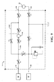
- the steering system 10 is a hydrostatic steering system that is adapted, i.e., configured, for use on off-highway vehicles (e.g., skid steers, combines, backhoes, etc.).
- the steering system 10 includes a fluid pump 12 in fluid communication with a fluid reservoir 14 and a steering unit 16 in fluid communication with the fluid pump 12 and a fluid motor 18.
- a priority valve 20 is disposed between the fluid pump 12 and the steering unit 16.
- the priority valve 20 is adapted to apportion fluid between a first circuit 22, including the steering unit 16 and the fluid motor 18, and a second circuit 24.
- the steering unit 16 includes a fluid inlet 26, a fluid outlet 28, a first control port 30 and a second control port 32.
- the fluid inlet 26 is in fluid communication with the fluid pump 12, while the fluid outlet 28 is in fluid communication with the fluid reservoir 14.
- the first and second control ports 30, 32 are in fluid communication with the fluid motor 18.
- the fluid motor 18 is a rotary device. It will be understood, however, that the scope of the present disclosure is not limited to the fluid motor being a rotary device as it could be a linear device.
- the fluid motor 18 is adapted to steer wheels of a vehicle (not shown) in response to fluid provided by the steering unit 16 at a given metered rate that corresponds to the magnitude of rotation of a steering wheel W.
- volumetric inefficiencies in the fluid motor 18 affect the responsiveness of the fluid motor 18 at low fluid metered rates from a conventional steering unit. These volumetric inefficiencies may be caused by leakage from within the fluid motor 18.
- slip or "dynamic slip” is used to describe a condition where a steering device (e.g., steering wheel, joystick, etc.) is actuated but the fluid motor 18 does not move in response to the actuation of the steering device. This lack of movement results when the fluid motor 18 does not receive an adequate supply of fluid upon initial actuation of the steering device.
- the volumetric inefficiencies are a result of the structure of the fluid motor 18 and, under such conditions when the relatively small fluid flow is sent from the steering unit 16 to the fluid motor 18, the fluid is allowed to leak through the fluid motor 18 without causing the desired rotary motion in the fluid motor 18.
- the steering unit 16 is shown.
- the steering unit 16 is adapted to reduce or eliminate the effect of the volumetric inefficiencies of the fluid motor 18.
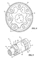
- the steering unit 16 includes an end plate 34, a fluid meter 36, a port plate 38, and a valve housing 40.
- a plurality of fasteners 42 e.g., bolts, etc. engage and retain the end plate 34, the fluid meter 36, the port plate 38, and the valve housing 40 together.
- the fluid meter 36 is a gerotor-type fluid meter.
- the fluid meter 36 includes an internally toothed ring 44 and an externally toothed star 46.
- the internally toothed ring 44 includes a plurality of internal teeth 45 which are circumferentially disposed.
- the externally toothed star 46 includes a plurality of external teeth 47, which are circumferentially disposed about the star 46.
- the internally toothed ring 44 and the externally toothed star 46 cooperatively define a plurality of expanding and contracting volume chambers 48.
- the number of volume chambers 48 is equal to the number of teeth disposed externally on the star 46 plus at least one.
- the teeth 47 of the star 46 are adapted to mesh with the teeth 45 of the ring 44 such that the star 46 rotates and orbits within the ring 44, causing the corresponding volume chambers 48 to continuously expand and contract.
- valve housing 40 defines the fluid inlet 26, the fluid outlet 28 and the first and second control ports 30, 32.
- the valve housing 40 further defines a valve bore 50.
- the valve bore 50 includes a central longitudinal axis 52.
- the valve housing 40 further defines a plurality of annular grooves 54a, 54b, 54c, 54d that are in fluid communication with the valve bore 50. More specifically, the grooves 54a-54d include a first groove 54a, a second groove 54b, a third groove 54c, and a fourth groove 54d.
- the first groove 54a is in fluid communication with the fluid inlet 26.
- the second groove 54b is in fluid communication with the fluid outlet 28.
- the third groove 54c is in fluid communication with the first control port 30 while the fourth groove 54d is in fluid communication with the second control port 32.
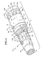
- a valve assembly 56 is disposed in the valve bore 50 of the housing 40 of the steering unit 16 so that the valve assembly 56 is selectively rotatable in the valve bore 50.
- the valve assembly 56 includes a sleeve 58 and a spool 60.
- the sleeve 58 is adapted to rotate about the central longitudinal axis 52 of the valve bore 50.
- the sleeve 58 includes a first end 62 and an oppositely disposed second end 64.
- the sleeve 58 defines a bore 66 that extends through the first and second ends 62, 64.
- the spool 60 is disposed in the bore 66 of the sleeve 58.
- the spool 60 is adapted to rotate in the bore 66 of the sleeve 58, about the longitudinal axis 52.
- the spool 60 includes a first end 68 and a second end 69.
- the first end 68 of the spool 60 has a reduced diameter and defines a set of internal splines 70 that provide a mechanical interface between the spool 60 and a steering wheel W (shown schematically in Figure 1 ).
- a main drive 72 is disposed within the spool 60 and mechanically couples the sleeve 58 of the valve assembly 56 to the star 46 of the fluid meter 36.
- the main drive 72 includes a first end 74 that includes a plurality of external splines 76 and an oppositely disposed second end 78.
- the external splines 76 of the first end 74 of the main drive 72 are engaged in meshing relationship with internal splines 80 of the star 46.
- the second end 78 of the main drive 74 may be bifurcated.
- the main drive 72 is connected to the sleeve 58 at the second end.
- a pin 82 passes through a pair of circumferentially elongated pin openings 83 defined in the spool 60 and a pair of pin holes 81 defined in the sleeve 58.
- the circumferentially elongated pin openings 83 have a first diameter D 1 and the pin holes 81 have a second diameter D2, which is less than the first diameter.
- the second diameter D2 pin holes 81 are sized to be small enough such that the pin 82 is retained to the sleeve 58 with limited free movement, i.e., a tightly controlled clearance fit.
- the first diameter D 1 of the pin openings 83 is larger than a diameter of the pin 82. Therefore, the difference between the diameter of the pin 82 and the first diameter D 1 of the pin openings 83 allows the spool 60 to be rotationally displaced from the sleeve 58.
- the spool 60 In operation, as the steering wheel W is turned, the spool 60 is rotationally displaced from the sleeve 58. This rotational displacement causes pressurized fluid from the fluid pump 12 to flow through the valve assembly 56, and into an expanding volume chamber 48 of the fluid meter 36.
- the star 46 As the pressurized fluid enters the expanding volume chamber 48 of the fluid meter 36, the star 46 orbits and rotates about a central axis 84 (shown as a "+" in Figure 4 ) of the ring 44.
- the orbital and rotational movement of the star 46 about the central axis 84 of the ring 44 causes the expanding volume chambers 48 to eventually become contracting volume chambers 48, where the pressurized fluid is expelled from the contracting volume chambers 46 of the fluid meter 36.
- the expelled pressurized fluid then flows through the valve assembly 54 to the fluid motor 18.
- the volume or quantity of the pressurized fluid flowing through the fluid meter 36 is metered or otherwise limited by the summation of volumes
- the engagement between the second end 78 of the main drive 72, the pin 82, and the sleeve 58 and the orbital and rotational movement of the star 46 within the ring 44 causes the sleeve 58 to rotate within the valve bore 50 of the valve housing 40.
- This rotation of the sleeve 58 in the valve bore 50 allows the sleeve 58 to "follow" the rotation of the spool 60, which maintains an appropriate relative rotational displacement between the spool 60 and the sleeve 58.
- the degree of displacement between the spool 60 and the sleeve 58 corresponds to a rate of rotation of the steering wheel W.
- the spool 60 is rotationally displaced from the sleeve 58 allowing fluid to flow to the fluid motor 18 at a first metered rate. If the rotation rate of the steering wheel W is increased, the rotational displacement of the spool 60 and the sleeve 58 is also increased, allowing fluid to flow to the fluid motor 18 at a second metered rate, where the second metered rate is higher than the first metered rate.
- the steering unit 16 further includes a plurality of leaf springs 86 or other biasing devices.
- the leaf springs 86 act on the sleeve 58 to bias the sleeve 58 toward a neutral position N, relative to the spool 60.
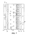
- the sleeve 58 of the valve assembly 56 includes an inner surface 90 and an outer surface 92, opposing the inner surface 90.
- the inner surface 90 is adapted to interface with the spool 60 while the outer surface 92 is adapted to interface with the valve bore 50 of the valve housing 40.
- the sleeve 58 defines an inlet groove 94 and an outlet groove 96.
- the inlet groove 94 is axially disposed on the sleeve 58 at a location that is adjacent to the second end 64 of the sleeve 58.
- the outlet groove 96 is axially disposed on the sleeve 58 at a location that is adjacent to the first end 62 of the sleeve 58.
- the inlet and outlet grooves 94, 96 extend circumferentially around the sleeve 58 to form annular grooves.
- the inlet groove 94 is adapted for fluid communication with the first groove 54a in the valve housing 40.
- the outlet groove 96 is adapted for fluid communication with the second groove 54b in the valve housing 40.
- the sleeve 58 defines a plurality of inlet openings 98 disposed in the inlet groove 94.
- the inlet openings 98 extend through the inner and outer surfaces 90, 92. In the depicted embodiment, there are twelve inlet openings 98, symmetrically disposed about the sleeve 58.
- the sleeve 58 further defines a first plurality of control openings 100 and a second plurality of control openings 102.
- the first plurality of control openings 100 are axially disposed on the sleeve 58 at a location that is between the inlet and outlet grooves 94, 96 of the sleeve 58.
- the first plurality of control openings 100 are in fluid communication with the third groove 54c of the valve housing 40. In the depicted embodiment, there are six control openings 100.
- the second plurality of control openings 102 are axially disposed on the sleeve 58 at a location that is between the first plurality of control openings 100 and the inlet groove 94.
- the second plurality of control openings 102 are circumferentially offset from the first plurality of control openings 100.
- the second plurality of control openings 102 are in fluid communication with the fourth groove 54d of the valve housing 40.
- the sleeve 58 further defines a plurality of meter ports 104a, 104b.
- the meter ports 104a, 104b of the sleeve 58 are adapted for fluid communication with a plurality of radial bores 106 defined in the valve housing 40.
- Each radial bore 106 in the valve housing 40 is in fluid communication with one of the volume chambers 48 of the fluid meter 36.
- the plurality of meter ports 104a, 104b are axially disposed on the sleeve 58 at a location that is between the inlet groove 94 and the second plurality of control openings 102.
- the sleeve 58 further defines a first bypass opening 108a and a second bypass opening 108b.
- the first and second bypass openings 108a, 108b are axially disposed on the sleeve 58 at a location that is between the second plurality of control openings 102 and the plurality of meter ports 104a, 104b. In the depicted embodiment, there are only two bypass openings 108a, 108b. The first and second bypass openings 108a, 108b will be described in greater detail subsequently.
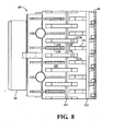
- the spool 60 includes an exterior surface 110.
- the exterior surface 110 of the spool 60 defines a first annular groove 112 and a second annular groove 114.
- the first annular groove 112 is axially disposed on the spool 60 at a location that is adjacent to the second end 69 of the spool 60.
- the second annular groove 114 is axially disposed on the spool 60 at a location that is between the first end 68 of the spool 60 and the first annular groove 112.
- the spool 60 further defines a plurality of inlet slots 116 that are in fluid communication with the first annular groove 112.
- the inlet slots 116 extend outwardly from the first annular groove 112 in an axial direction toward the first end 68 of the spool 60.
- the plurality of inlet slots 116 are in fluid communication with the plurality of inlet openings 98 of the sleeve 58 when the spool 60 is rotationally displaced from the sleeve 58.
- the spool 60 further defines a plurality of first control slots 118 that are in fluid communication with the second annular groove 114.
- the plurality of first control slots 118 extend axially along a portion of the spool 60 and are adapted to provide fluid communication between the second meter ports 104b of the sleeve 58 and the first and second plurality of control openings 100, 102 when the spool 60 is rotationally displaced from the sleeve 58.
- the plurality of first control slots 118 provide fluid communication between the second meter ports 104b and the second plurality of control openings 102 in the sleeve 58.
- the plurality of first control slots 118 provides fluid communication between the second meter ports 104b and the first plurality of control openings 100 in the sleeve 58.
- the spool 60 defines a plurality of second control slots 120.
- the second control slots 120 extend axially along a portion of the spool 60 and are adapted to provide fluid communication between the first and second pluralities of control openings 100, 102 of the sleeve 58 and the second groove 54b of the valve housing 40 when the first or second plurality of control openings 100, 102 are radially aligned with the second control slots 120.
- the first and second control slots 118, 120 are alternately disposed about the sleeve 58.
- the spool 60 further defines a first bypass passage 122a and a second bypass passage 122b.
- the first and second bypass passages 122a, 122b are in fluid communication with the second annular groove 114.
- Each of the first and second bypass passages 122a, 122b extend outwardly from the second annular groove 114 in an axial direction toward the second end 69 of the spool 60.
- the first and second bypass passages 122a, 122b are disposed between two immediately adjacent first control slots 118. In the depicted embodiment, a portion of one of the inlet slots 116 is disposed partly between the first and second bypass passages 122a, 122b.
- the first and second bypass passages 122a, 122b will be explained in more detail below.
- Fluid from the fluid pump 12 enters the fluid inlet 26 of the steering unit 16.
- the fluid from the fluid inlet 26 is communicated to the first groove 54a in the valve housing 40.
- fluid From the first groove 54a, fluid enters the inlet groove 94 of the sleeve 58.
- Fluid from the inlet groove 94 of the sleeve 58 is communicated to the inlet slots 116 in the spool 60 through first variable orifices A1 (shown in Figure 9 ) in the valve assembly 56.
- the first variable orifices A1 are defined by the overlap between the inlet openings 98 in the sleeve 58 and the corresponding inlet slots 116 in the spool 60.
- the size of the first variable orifices A1 varies based on the amount of relative rotational displacement between the spool 60 and the sleeve 58. More specifically, as the rotational displacement between the spool 60 and the sleeve 58 increases, the size of each of the first variable orifices A 1 increases.
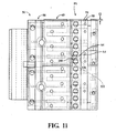
- Fluid flowing within the inlet slots 116 defined in the spool 60 then flows through second variable orifices A2 (shown in Figures 1 , 9 , and 12 ) which are defined by the overlap between the inlet slots 116 of the spool 60 and the first meter ports 104a of the sleeve 58.
- the size of the second variable orifices A2 varies based on the amount of relative rotational displacement between the spool 60 and the sleeve 58.
- the fluid flowing out through the first meter ports 104a are then communicated to the corresponding volume chambers 48, which are expanding, through the corresponding radial bores 106 defined in the valve housing 40
- the expanding volume chambers 48 containing the fluid, transforms into the volume chambers 48, which are contracting
- fluid from the contracting volume chambers 48 is communicated to the second meter ports 104b through the radial bores 106 in the valve housing 40.
- the fluid is communicated to the first control slots 118 in the sleeve 58 through third variable orifices A3 (shown in Figures 1 , 9 , and 12 ) in the valve assembly 56.
- the third variable orifices A3 are created by the overlap between the second meter ports 104b defined in the sleeve 58 and the first control slots 118 defined in the spool 60, where the overlap results from rotational displacement of the spool 60 relative to the sleeve 58.
- the size of the third variable orifices A3 varies based on the amount of relative rotational displacement between the spool 60 and the sleeve 58
- the valve assembly 56 includes a plurality of fourth variable orifices A4 which are defined by an overlap between the first control slots 118 defined in the spool 60 and the first or second plurality of control openings 100, 102 defined in the sleeve 58, where the overlap results from rotational displacement of the spool 60 relative to the sleeve 58.
- Fluid passing through the fourth variable orifices A4 flows through the third or fourth grooves 54c, 54d, defined in the valve housing 40, and into the fluid motor 18 through the respective first and second control ports 30, 32.
- the size of the fourth variable orifices A4 varies based on the amount of relative rotational displacement between the spool 60 and the sleeve 58
- Fluid from the fluid motor 18 is communicated to the second groove 54b defined in the valve housing 40 through a plurality of fifth variable orifices A5 defined in the valve assembly 56 ( Figures 1 , 9 , and 12 ).
- the fifth variable orifices A5 are defined by an overlap between the first or second plurality of control openings 100, 102 defined in the sleeve 58 and the second control slots 120 defined in the spool 60, where the overlap results from rotational displacement of the spool 60 relative to the sleeve 58.
- the size of the fifth variable orifices A5 varies based on the amount of relative rotational displacement between the spool 60 and the sleeve 58
- variable orifices A1-A5 When the spool 60 is not rotationally displaced relative to the sleeve 58 (i.e., when the valve assembly 56 is in the neutral position N), the spool 60 is in a closed position P0 and the variable orifices A1-A5 are blocked (best shown in Figures 1 and 10 ). When the spool is rotationally displaced relative to the sleeve 58, the variable orifices A1-A5 begin to open.
- volumetric inefficiencies in the fluid motor 18 make the motor unresponsive to low flow rates (i.e., small rotational displacements between the spool 60 and the sleeve 58). This unresponsiveness of the fluid motor 18 to low flow rates means that when the steering wheel W is rotated at low revolutions per minute, the fluid motor 18 is not actuated.
- the valve assembly 56 of the steering unit 16 includes a secondary fluid path 126 (shown in Figure 9 ) through the steering unit 16.
- the secondary fluid path 126 provides a path through the valve assembly 56 through which fluid from the fluid inlet 26 is communicated to one of the first and second control ports 30, 32, while bypassing the fluid meter 36.
- the secondary fluid path 126 provides an amount of fluid, in addition to the fluid provided through the primary fluid path 124 of the valve assembly 56, to the fluid motor 18 at low revolutions per minute of the steering wheel W.
- the additional amount of fluid flowing through the secondary fluid path 126 of the valve assembly 56 compensates for fluid that bypasses a displacement assembly (e.g., gerotor set, piston assembly, radial piston assembly, cam-lobe assembly, vane assembly, etc.) of the fluid motor 18 to reduce dynamic slip.
- a displacement assembly e.g., gerotor set, piston assembly, radial piston assembly, cam-lobe assembly, vane assembly, etc.
- the secondary fluid path 126 through the valve assembly 56 closes.
- the secondary fluid path 126 is only open at small rotational displacements of the valve assembly 56. In one embodiment, the secondary fluid path 126 is only open when the rotational displacement of the spool 60 relative to the sleeve 58 is less than or equal to about 5°. In another embodiment, the secondary fluid path 126 is only active when the rotational displacement of the spool 60 relative to the sleeve 58 is in a range of about 3° to about 5°. In another embodiment, the secondary fluid path 126 is only active when the rotational displacement of the spool 60 relative to the sleeve 58 is in a range of about 3.7° to about 5°.
- the secondary fluid path 126 includes a bypass orifice A6, hereinafter referred to as a sixth variable orifice A6, disposed downstream of the first variable orifices A1 and upstream of the fourth variable orifices A4.
- a bypass orifice A6 hereinafter referred to as a sixth variable orifice A6, disposed downstream of the first variable orifices A1 and upstream of the fourth variable orifices A4.
- the disposition of the sixth variable orifice A6 between the first and fourth variable orifices A1, A4 prevents fluid from being communicated to the fluid motor 18 before actuation of the steering wheel W.
- the sixth variable orifice A6 provides a path through which fluid bypasses the second and third variable orifices A2, A3 and therefore bypasses the fluid meter 36.
- the sixth variable orifice A6 provides a direct path from one of the inlet slots 116 to the first control slots 118.
- the sixth variable orifice A6 is formed by the overlap between one of the first and second bypass openings 108a, 108b of the sleeve 58 with one of the inlet slots 116 and one of the first and second bypass passages 122a, 122b of the spool 60.
- the volume of fluid which is permitted to flow through the sixth variable orifice A6 is configured to be sufficient to compensate to the leakage of the corresponding fluid motor 18.
- the volume of fluid permitted to flow through the sixth variable orifice A6 and into the fluid motor 18 may be configured based on the size of the first and second bypass openings 108a, 108b of the sleeve 58, the size of the inlet slots 116, and/or the size of the first and second bypass passages 122a, 122b of the spool 60. Additionally, the volume of fluid permitted to flow through the sixth variable orifice A6 and into the fluid motor 18 may be influenced by the amount of fluid permitted to through the first variable orifice A1 and/or the fourth variable orifice A4.
- the spool 60 is in a first open position P1 and the first variable orifice A1, formed between the inlet openings 98 of the sleeve and the inlet slots 116 in the spool 60, opens.
- the angular displacement between the spool 60 and the sleeve 58 is linearly represented in the layout in Figure 11 as angle a. Therefore, fluid from the fluid inlet 26 is communicated to the inlet slots 116 through the first variable orifice A1.
- Fluid in the inlet grooves 116 is communicated to the first bypass passage 122a in the spool 60 through the first bypass opening 108a in the sleeve 58, which overlaps one of the inlet grooves 116 and the first bypass passage 122a.
- the fluid in the fluid bypass passage 122a in the spool is communicated to the first control slots 118 through the second annular groove 114.
- the size of the first variable orifice A1 increases so that more fluid is communicated to the inlet grooves 116 in the spool 60, and the spool 60 moves to the second open position P2.
- the sixth variable orifice A6 closes. While the fluid bypass opening 108a in the sleeve 58 overlaps the fluid bypass passage 122a in the spool 60, the fluid bypass opening 108a does not overlap the inlet groove 116. Therefore, the secondary fluid path 126 is closed.
- the amount of fluid that passes through the secondary fluid path 126 is a function of the size of the fluid bypass opening 108 and distance between the fluid bypass passage 122 and the inlet slot 116 immediately adjacent to the fluid bypass passage 122.
- Spools 60 and sleeves 58 with different sizes for the fluid bypass opening 108 and different distances between the fluid bypass passage 122 and the inlet slot 116 can be manufactured to account for different fluid motor 18 efficiencies.
- a given valve assembly 56 with a given size fluid bypass opening 108 and a given distance between the fluid bypass passage 122 and the inlet slot 116 may be used with fluid motors 18 whose efficiencies differ by less than or equal to about 15%.
- the given valve assembly 56 may be used with different fluid motors 18 whose efficiencies differ by less than or equal to about 10%. In another embodiment, the given valve assembly 56 may be used with different fluid motors 18 whose efficiencies differ by less than or equal to about 5%.
Landscapes
- Engineering & Computer Science (AREA)
- Chemical & Material Sciences (AREA)
- Combustion & Propulsion (AREA)
- Transportation (AREA)
- Mechanical Engineering (AREA)
- Power Steering Mechanism (AREA)
Claims (9)
- Unité de direction (16) configurée pour être fixée sur un volant de direction (W) et configurée pour être en communication fluidique avec un moteur hydraulique (18), l'unité de direction (16) comprenant :un débitmètre de fluide (36) configuré pour mesurer le fluide parvenant au moteur hydraulique (18) en réponse à l'actionnement de l'unité de direction (16) ;un boîtier de soupape (40) en communication fluidique avec le débitmètre de fluide (36), le boîtier de soupape définissant un alésage de soupape (50) ;un ensemble soupape (56) disposé dans l'alésage de soupape (50) et configuré pour recevoir une entrée à partir du volant de direction (W) ;dans laquelle l'ensemble soupape (56) définit un chemin de fluide primaire (124) vers le débitmètre de fluide (36) et vers le moteur hydraulique (18) à partir du débitmètre de fluide (36) ;caractérisée en ce que l'ensemble soupape (56) définit en outre un chemin de fluide secondaire (126) vers le moteur hydraulique (18) qui contourne le débitmètre de fluide (36), l'ensemble soupape (56) comportant :un manchon (58) comportant une surface interne (90) opposée à une surface externe (92), dans lequel la surface interne (9C) définit un alésage (66) s'étendant le long d'un axe longitudinal central (52) ;dans laquelle le manchon (58) définit une ouverture de dérivation (108a, 108b) ; une bobine (60) disposée dans l'alésage (66) du manchon (58) et configurée pour être déplacée en rotation par rapport au manchon (58) autour de l'axe longitudinal central (52) pour se déplacer entre une position fermée (P0), une première position ouverte (P1), et une deuxième position ouverte (P2) en réponse à une entrée à partir du volant de direction (W) ;dans laquelle la bobine (60) définit une fente d'entrée (116) et un passage de dérivation (122a, 122b) ;dans laquelle la bobine (60) coopère avec le manchon (58) pour définir un premier et un quatrième orifice variable (A1), (A4) lorsque la bobine (60) est dans la première position ouverte (P1) ;dans laquelle l'ouverture de dérivation (108a, 108b) du manchon (58) se chevauche avec la fente d'entrée (116) et le passage de dérivation (122a, 122b) pour définir un orifice de dérivation (A6) situé sur le chemin de fluide secondaire (126) lorsque la bobine (60) est dans la première position ouverte (P1) de sorte que le fluide s'écoule à travers le chemin de fluide secondaire (126) vers le moteur hydraulique (18), par l'intermédiaire du premier orifice variable (A1), le quatrième orifice variable (A4), et l'orifice de dérivation (A6) en fonction d'une inefficacité volumétrique du moteur hydraulique (18) ;dans laquelle l'orifice de dérivation (A6) est disposé de manière opérationnelle en aval du premier orifice variable (A1) et disposé de manière opérationnelle en amont du quatrième orifice variable (A4) de sorte qu'un fluide soit empêché d'être en communication avec le moteur hydraulique (18) avant l'entrée à partir du volant de direction (W) ; etdans laquelle le fluide est empêché de s'écouler à travers le chemin de fluide secondaire (126) vers le moteur hydraulique (18) lorsque la bobine (60) n'est pas dans la première position ouverte (P1).
- Unité de direction (16), tel que revendiquée dans la revendication 1, dans laquelle le manchon (58) définit :une première ouverture de commande (100) et une deuxième ouverture de commande (102), espacée de manière axiale de la première ouverture de commande (100) ;un premier orifice de débitmètre (104a) et un deuxième orifice de débitmètre (104b) ; etune ouverture d'entrée (98) ;dans laquelle l'ouverture de dérivation (108a, 108b) est disposée axialement entre la deuxième ouverture de commande (102) et le premier et le deuxième orifice de débitmètre (104a), (104b).
- Unité de direction (16), tel que revendiquée dans la revendication 1, dans laquelle la bobine (60) définit :une première rainure annulaire (54a) et une deuxième rainure annulaire (54b) ; etune première fente de commande (118) en communication fluidique avec la deuxième rainure annulaire (54b) ;dans laquelle la première fente de commande (118) de la bobine (60) est configurée pour fournir une communication fluidique entre le deuxième orifice de débitmètre (104b) du manchon (58) et les première et deuxième ouvertures de commande (100), (102) du manchon (58) lorsque la bobine (60) se déplace en rotation, par rapport au manchon (58).
- Unité de direction (16), tel que revendiquée dans la revendication 3, dans laquelle la bobine (60) définit en outre une deuxième fente de commande (120) en communication fluidique avec les première et deuxième ouvertures de commande (100), (102) du manchon (58) lorsque l'une des première et deuxième ouvertures de commande (100), (102) du manchon (58) sont alignées de manière radiale avec la deuxième fente de commande (120) de la bobine (60) lorsque la bobine (60) est déplacée en rotation par rapport au manchon (58).
- Unité de direction (16), tel que revendiquée dans la revendication 4, dans laquelle l'ensemble soupape (56) définit en outre un deuxième et un troisième orifice variable (A2), (A3) ;
dans laquelle le premier orifice variable (A1) est défini par un chevauchement entre l'ouverture d'entrée (98) du manchon (58) et la fente d'entrée (116) de la bobine (60) ;
dans laquelle le deuxième orifice variable (A2) est défini par un chevauchement entre la fente d'entrée (116) de la bobine (60) et le premier orifice de débitmètre (104a) du manchon (58) ;
dans laquelle le troisième orifice variable (A3) est défini par un chevauchement entre le deuxième orifice de débitmètre (104b) défini dans le manchon (58) et la première fente de commande (118) définie dans la bobine (60) ; et
dans laquelle le quatrième orifice variable (A4) est défini par un chevauchement entre la première fente de commande (118) définie dans la bobine (60) et l'une parmi la première et la deuxième pluralité d'ouvertures de commande (100), (102) définies dans le manchon (58). - Unité de direction (16), tel que revendiquée dans la revendication 5, dans laquelle la bobine (60) est configurée de manière à ce qu'elle soit déplacée en rotation par rapport au manchon (58) autour de l'axe longitudinal central (52) pour se déplacer entre la position fermée (P0) (P1), la première position ouverte (P1), et la deuxième position ouverte (P2) en réponse à une entrée à partir du volant de direction (W) ;
dans laquelle le fluide s'écoule à travers le premier orifice variable (A1), l'orifice de dérivation (A6), et le quatrième orifice variable (A4) au moteur hydraulique (18) lorsque la bobine (60) est dans la première position ouverte (P1) ; et
dans laquelle le fluide s'écoule à travers les premier, deuxième, troisième et quatrième orifices variables (A1), (A2), (A3), (A4) au moteur hydraulique (18) lorsque la bobine (60) est dans la deuxième position ouverte (P2). - Unité de direction (16), tel que revendiquée dans la revendication 6, dans laquelle l'orifice de dérivation (A6) est dans la première position ouverte (P1) lorsque le déplacement en rotation (a) de la bobine (60), par rapport au manchon (58), est inférieure ou égale à environ 5 degrés ; et
dans laquelle les premier, deuxième, et troisième orifices variables (A1), (A2), (A3) sont uniquement dans la deuxième position ouverte (P2) lorsque le déplacement en rotation (a) de la bobine (60), par rapport au manchon (58), est supérieure à environ 5 degrés. - Unité de direction (16), tel que revendiquée dans la revendication 6, dans laquelle plus de fluide est autorisé à s'écouler à travers chacun des premier et quatrième orifices variables (A1), (A4) lorsque l'ensemble soupape (56) est dans la deuxième position ouverte (P2) (56) que lorsque l'ensemble soupape est dans la première position ouverte (P1).
- Unité de direction (16), tel que revendiquée dans la revendication 5, dans laquelle le boîtier de soupape (40) définit une première, deuxième, troisième et quatrième rainure (54a), (54b), (54c), (54d) en communication fluidique avec l'alésage de soupape (50) ;
dans laquelle la première rainure (54a) est configurée pour être en communication fluidique avec la rainure d'entrée (94) du manchon (58) de sorte que le fluide s'écoule à partir de la première rainure (54a) et dans le manchon (58) ;
dans laquelle la deuxième rainure (54b) est configurée pour être en communication fluidique avec la rainure de sortie (96) du manchon (58) de sorte que le fluide s'écoule à partir de la rainure de sortie (96) et dans la deuxième rainure (54b) ;
dans laquelle la troisième rainure (54c) est configurée pour être en communication fluidique avec la première ouverture de commande (100) du manchon (58) de sorte que le fluide s'écoule à partir de la première ouverture de commande (100) et dans le moteur hydraulique (18) ; et
dans lequel la quatrième rainure (54d) est configurée pour être en communication fluidique avec la deuxième ouverture de commande (102) du manchon (58) de sorte que le fluide s'écoule à partir du moteur hydraulique (18) et dans la première ouverture de commande (100).
Applications Claiming Priority (3)
| Application Number | Priority Date | Filing Date | Title |
|---|---|---|---|
| US34732610P | 2010-05-21 | 2010-05-21 | |
| US13/111,212 US9238479B2 (en) | 2010-05-21 | 2011-05-19 | Steering system with dynamic slip reduction |
| PCT/US2011/037338 WO2011146834A1 (fr) | 2010-05-21 | 2011-05-20 | Système de direction avec réduction dynamique du patinage |
Publications (2)
| Publication Number | Publication Date |
|---|---|
| EP2571745A1 EP2571745A1 (fr) | 2013-03-27 |
| EP2571745B1 true EP2571745B1 (fr) | 2014-06-18 |
Family
ID=44626717
Family Applications (1)
| Application Number | Title | Priority Date | Filing Date |
|---|---|---|---|
| EP11723806.3A Not-in-force EP2571745B1 (fr) | 2010-05-21 | 2011-05-20 | Système de direction avec réduction dynamique du patinage |
Country Status (3)
| Country | Link |
|---|---|
| US (1) | US9238479B2 (fr) |
| EP (1) | EP2571745B1 (fr) |
| WO (1) | WO2011146834A1 (fr) |
Families Citing this family (7)
| Publication number | Priority date | Publication date | Assignee | Title |
|---|---|---|---|---|
| US10633015B2 (en) | 2017-04-14 | 2020-04-28 | Deere & Company | Hydraulic steering system |
| US10876272B2 (en) | 2018-08-10 | 2020-12-29 | Caterpillar Inc. | Systems and methods for controlling a machine implement |
| JP7242239B2 (ja) | 2018-10-09 | 2023-03-20 | 仁科工業株式会社 | パワーステアリングバルブ |
| DE102020106437B4 (de) | 2020-03-10 | 2024-09-26 | Danfoss Power Solutions Aps | Fluidsteuereinrichtung, insbesondere als Teil einer hydraulischen Lenkeinheit |
| DE102020106440B4 (de) * | 2020-03-10 | 2024-08-01 | Danfoss Power Solutions Aps | Hydraulische Lenkeinheit |
| DE102020106438B4 (de) | 2020-03-10 | 2022-03-31 | Danfoss Power Solutions Aps | Fluidsteuereinrichtung, insbesondere als Teil einer hydraulischen Lenkeinheit |
| US11891278B1 (en) | 2022-08-31 | 2024-02-06 | Caterpillar Inc. | Lifting capacity systems and methods for lifting machines |
Family Cites Families (11)
| Publication number | Priority date | Publication date | Assignee | Title |
|---|---|---|---|---|
| US4759182A (en) | 1987-07-24 | 1988-07-26 | Eaton Corporation | Steering control unit with flow amplification |
| US4862690A (en) * | 1988-10-06 | 1989-09-05 | Eaton Corporation | Steering control unit with both flow amplification and manual steering capability |
| US4838314A (en) | 1988-10-12 | 1989-06-13 | Deere & Company | Secondary hydraulic steering system |
| DE4042151C2 (de) | 1990-12-28 | 1996-12-12 | Danfoss As | Steuereinrichtung für ein vollhydraulisches Lenksystem |
| DE59600349D1 (de) * | 1996-11-02 | 1998-08-20 | Hydraulik Nord Gmbh | Hydraulische Lenkeinrichtung mit Übersetzungsänderung und Stromverstärkung |
| US5819532A (en) | 1997-06-06 | 1998-10-13 | Eaton Corporation | Dynamic load signal fluid controller with instant on flow amplification |
| JP3577250B2 (ja) * | 1999-12-07 | 2004-10-13 | イートン機器株式会社 | オープンセンタ型全油圧式パワーステアリング装置 |
| US6318078B1 (en) * | 2000-05-12 | 2001-11-20 | Eaton Corporation | Fluid controller and fluid meter bypass arrangement |
| US20020179161A1 (en) | 2001-05-30 | 2002-12-05 | Eaton Corporation | Low slip steering system and improved fluid controller therefor |
| DE10321109B4 (de) | 2003-05-09 | 2005-12-08 | Sauer-Danfoss Aps | Leckagekompensierungsanordnung in einer Steuereinrichtung für ein vollhydraulisches Lenksystem |
| US7028469B2 (en) | 2002-10-08 | 2006-04-18 | Sauer-Danfoss Aps | Leakage compensation arrangement in a control device for a fully hydraulic steering system |
-
2011
- 2011-05-19 US US13/111,212 patent/US9238479B2/en not_active Expired - Fee Related
- 2011-05-20 WO PCT/US2011/037338 patent/WO2011146834A1/fr not_active Ceased
- 2011-05-20 EP EP11723806.3A patent/EP2571745B1/fr not_active Not-in-force
Also Published As
| Publication number | Publication date |
|---|---|
| WO2011146834A1 (fr) | 2011-11-24 |
| EP2571745A1 (fr) | 2013-03-27 |
| US20110283694A1 (en) | 2011-11-24 |
| US9238479B2 (en) | 2016-01-19 |
Similar Documents
| Publication | Publication Date | Title |
|---|---|---|
| EP2571745B1 (fr) | Système de direction avec réduction dynamique du patinage | |
| EP2250068B1 (fr) | Contrôleur de fluide doté de multiples débitmètres | |
| EP0388711B1 (fr) | Commande de direction à amplification du débit et à centre ouvert | |
| JP4725695B2 (ja) | 流体コントローラ | |
| US3931711A (en) | Controller assembly | |
| US4488569A (en) | Apparatus with staged pressure differential for controlling fluid flow | |
| US4781219A (en) | Fluid controller and dampening fluid path | |
| EP0775623B1 (fr) | Commande de direction à amplification du débit pour piston à surfaces inégales | |
| USRE34746E (en) | Open-center steering control unit with flow amplification | |
| JP4329089B2 (ja) | 流体コントローラ | |
| US6769451B2 (en) | Power beyond steering unit with bypass | |
| KR0171429B1 (ko) | 일체보조 밸빙을 구비한 유체제어기 | |
| JP4122473B2 (ja) | スリップを低減したステアリングシステムに用いる流体制御器 | |
| EP0498223B1 (fr) | Unité de commande de direction pour une pluralité d'essieux directeurs | |
| EP0264613A2 (fr) | Système de commande de fluide et trajet de fluide amorti | |
| EP0846607B1 (fr) | Soupape de commande pour direction assistée. | |
| EP0854074B1 (fr) | Soupape de commande de direction assistée avec réduction de bruit | |
| US20150204324A1 (en) | Drive Assembly for a Rotary Fluid Pressure Device | |
| JP3577250B2 (ja) | オープンセンタ型全油圧式パワーステアリング装置 | |
| JP3690877B2 (ja) | ラックピニオン式油圧パワーステアリング装置およびその製造方法 | |
| WO2013165737A2 (fr) | Circuit de direction à soupape de dérivation | |
| JPH076012Y2 (ja) | 車両用差動制限装置 |
Legal Events
| Date | Code | Title | Description |
|---|---|---|---|
| PUAI | Public reference made under article 153(3) epc to a published international application that has entered the european phase |
Free format text: ORIGINAL CODE: 0009012 |
|
| 17P | Request for examination filed |
Effective date: 20121212 |
|
| AK | Designated contracting states |
Kind code of ref document: A1 Designated state(s): AL AT BE BG CH CY CZ DE DK EE ES FI FR GB GR HR HU IE IS IT LI LT LU LV MC MK MT NL NO PL PT RO RS SE SI SK SM TR |
|
| DAX | Request for extension of the european patent (deleted) | ||
| GRAP | Despatch of communication of intention to grant a patent |
Free format text: ORIGINAL CODE: EPIDOSNIGR1 |
|
| INTG | Intention to grant announced |
Effective date: 20131016 |
|
| GRAP | Despatch of communication of intention to grant a patent |
Free format text: ORIGINAL CODE: EPIDOSNIGR1 |
|
| INTG | Intention to grant announced |
Effective date: 20140129 |
|
| GRAS | Grant fee paid |
Free format text: ORIGINAL CODE: EPIDOSNIGR3 |
|
| GRAA | (expected) grant |
Free format text: ORIGINAL CODE: 0009210 |
|
| AK | Designated contracting states |
Kind code of ref document: B1 Designated state(s): AL AT BE BG CH CY CZ DE DK EE ES FI FR GB GR HR HU IE IS IT LI LT LU LV MC MK MT NL NO PL PT RO RS SE SI SK SM TR |
|
| RAP1 | Party data changed (applicant data changed or rights of an application transferred) |
Owner name: EATON CORPORATION |
|
| REG | Reference to a national code |
Ref country code: GB Ref legal event code: FG4D |
|
| REG | Reference to a national code |
Ref country code: CH Ref legal event code: EP |
|
| REG | Reference to a national code |
Ref country code: AT Ref legal event code: REF Ref document number: 673158 Country of ref document: AT Kind code of ref document: T Effective date: 20140715 |
|
| REG | Reference to a national code |
Ref country code: IE Ref legal event code: FG4D |
|
| REG | Reference to a national code |
Ref country code: DE Ref legal event code: R096 Ref document number: 602011007793 Country of ref document: DE Effective date: 20140731 |
|
| PG25 | Lapsed in a contracting state [announced via postgrant information from national office to epo] |
Ref country code: GR Free format text: LAPSE BECAUSE OF FAILURE TO SUBMIT A TRANSLATION OF THE DESCRIPTION OR TO PAY THE FEE WITHIN THE PRESCRIBED TIME-LIMIT Effective date: 20140919 Ref country code: NO Free format text: LAPSE BECAUSE OF FAILURE TO SUBMIT A TRANSLATION OF THE DESCRIPTION OR TO PAY THE FEE WITHIN THE PRESCRIBED TIME-LIMIT Effective date: 20140918 Ref country code: CY Free format text: LAPSE BECAUSE OF FAILURE TO SUBMIT A TRANSLATION OF THE DESCRIPTION OR TO PAY THE FEE WITHIN THE PRESCRIBED TIME-LIMIT Effective date: 20140618 Ref country code: LT Free format text: LAPSE BECAUSE OF FAILURE TO SUBMIT A TRANSLATION OF THE DESCRIPTION OR TO PAY THE FEE WITHIN THE PRESCRIBED TIME-LIMIT Effective date: 20140618 Ref country code: FI Free format text: LAPSE BECAUSE OF FAILURE TO SUBMIT A TRANSLATION OF THE DESCRIPTION OR TO PAY THE FEE WITHIN THE PRESCRIBED TIME-LIMIT Effective date: 20140618 |
|
| REG | Reference to a national code |
Ref country code: NL Ref legal event code: VDEP Effective date: 20140618 |
|
| REG | Reference to a national code |
Ref country code: AT Ref legal event code: MK05 Ref document number: 673158 Country of ref document: AT Kind code of ref document: T Effective date: 20140618 |
|
| REG | Reference to a national code |
Ref country code: LT Ref legal event code: MG4D |
|
| PG25 | Lapsed in a contracting state [announced via postgrant information from national office to epo] |
Ref country code: LV Free format text: LAPSE BECAUSE OF FAILURE TO SUBMIT A TRANSLATION OF THE DESCRIPTION OR TO PAY THE FEE WITHIN THE PRESCRIBED TIME-LIMIT Effective date: 20140618 Ref country code: RS Free format text: LAPSE BECAUSE OF FAILURE TO SUBMIT A TRANSLATION OF THE DESCRIPTION OR TO PAY THE FEE WITHIN THE PRESCRIBED TIME-LIMIT Effective date: 20140618 Ref country code: HR Free format text: LAPSE BECAUSE OF FAILURE TO SUBMIT A TRANSLATION OF THE DESCRIPTION OR TO PAY THE FEE WITHIN THE PRESCRIBED TIME-LIMIT Effective date: 20140618 Ref country code: SE Free format text: LAPSE BECAUSE OF FAILURE TO SUBMIT A TRANSLATION OF THE DESCRIPTION OR TO PAY THE FEE WITHIN THE PRESCRIBED TIME-LIMIT Effective date: 20140618 |
|
| PG25 | Lapsed in a contracting state [announced via postgrant information from national office to epo] |
Ref country code: PT Free format text: LAPSE BECAUSE OF FAILURE TO SUBMIT A TRANSLATION OF THE DESCRIPTION OR TO PAY THE FEE WITHIN THE PRESCRIBED TIME-LIMIT Effective date: 20141020 Ref country code: SK Free format text: LAPSE BECAUSE OF FAILURE TO SUBMIT A TRANSLATION OF THE DESCRIPTION OR TO PAY THE FEE WITHIN THE PRESCRIBED TIME-LIMIT Effective date: 20140618 Ref country code: EE Free format text: LAPSE BECAUSE OF FAILURE TO SUBMIT A TRANSLATION OF THE DESCRIPTION OR TO PAY THE FEE WITHIN THE PRESCRIBED TIME-LIMIT Effective date: 20140618 Ref country code: ES Free format text: LAPSE BECAUSE OF FAILURE TO SUBMIT A TRANSLATION OF THE DESCRIPTION OR TO PAY THE FEE WITHIN THE PRESCRIBED TIME-LIMIT Effective date: 20140618 Ref country code: CZ Free format text: LAPSE BECAUSE OF FAILURE TO SUBMIT A TRANSLATION OF THE DESCRIPTION OR TO PAY THE FEE WITHIN THE PRESCRIBED TIME-LIMIT Effective date: 20140618 Ref country code: RO Free format text: LAPSE BECAUSE OF FAILURE TO SUBMIT A TRANSLATION OF THE DESCRIPTION OR TO PAY THE FEE WITHIN THE PRESCRIBED TIME-LIMIT Effective date: 20140618 |
|
| PG25 | Lapsed in a contracting state [announced via postgrant information from national office to epo] |
Ref country code: NL Free format text: LAPSE BECAUSE OF FAILURE TO SUBMIT A TRANSLATION OF THE DESCRIPTION OR TO PAY THE FEE WITHIN THE PRESCRIBED TIME-LIMIT Effective date: 20140618 Ref country code: PL Free format text: LAPSE BECAUSE OF FAILURE TO SUBMIT A TRANSLATION OF THE DESCRIPTION OR TO PAY THE FEE WITHIN THE PRESCRIBED TIME-LIMIT Effective date: 20140618 Ref country code: IS Free format text: LAPSE BECAUSE OF FAILURE TO SUBMIT A TRANSLATION OF THE DESCRIPTION OR TO PAY THE FEE WITHIN THE PRESCRIBED TIME-LIMIT Effective date: 20141018 Ref country code: AT Free format text: LAPSE BECAUSE OF FAILURE TO SUBMIT A TRANSLATION OF THE DESCRIPTION OR TO PAY THE FEE WITHIN THE PRESCRIBED TIME-LIMIT Effective date: 20140618 |
|
| REG | Reference to a national code |
Ref country code: DE Ref legal event code: R097 Ref document number: 602011007793 Country of ref document: DE |
|
| PLBE | No opposition filed within time limit |
Free format text: ORIGINAL CODE: 0009261 |
|
| STAA | Information on the status of an ep patent application or granted ep patent |
Free format text: STATUS: NO OPPOSITION FILED WITHIN TIME LIMIT |
|
| PG25 | Lapsed in a contracting state [announced via postgrant information from national office to epo] |
Ref country code: IT Free format text: LAPSE BECAUSE OF FAILURE TO SUBMIT A TRANSLATION OF THE DESCRIPTION OR TO PAY THE FEE WITHIN THE PRESCRIBED TIME-LIMIT Effective date: 20140618 Ref country code: DK Free format text: LAPSE BECAUSE OF FAILURE TO SUBMIT A TRANSLATION OF THE DESCRIPTION OR TO PAY THE FEE WITHIN THE PRESCRIBED TIME-LIMIT Effective date: 20140618 |
|
| 26N | No opposition filed |
Effective date: 20150319 |
|
| PG25 | Lapsed in a contracting state [announced via postgrant information from national office to epo] |
Ref country code: BE Free format text: LAPSE BECAUSE OF FAILURE TO SUBMIT A TRANSLATION OF THE DESCRIPTION OR TO PAY THE FEE WITHIN THE PRESCRIBED TIME-LIMIT Effective date: 20140618 |
|
| REG | Reference to a national code |
Ref country code: DE Ref legal event code: R097 Ref document number: 602011007793 Country of ref document: DE Effective date: 20150319 |
|
| PG25 | Lapsed in a contracting state [announced via postgrant information from national office to epo] |
Ref country code: SI Free format text: LAPSE BECAUSE OF FAILURE TO SUBMIT A TRANSLATION OF THE DESCRIPTION OR TO PAY THE FEE WITHIN THE PRESCRIBED TIME-LIMIT Effective date: 20140618 |
|
| REG | Reference to a national code |
Ref country code: CH Ref legal event code: PL |
|
| GBPC | Gb: european patent ceased through non-payment of renewal fee |
Effective date: 20150520 |
|
| PG25 | Lapsed in a contracting state [announced via postgrant information from national office to epo] |
Ref country code: LI Free format text: LAPSE BECAUSE OF NON-PAYMENT OF DUE FEES Effective date: 20150531 Ref country code: LU Free format text: LAPSE BECAUSE OF FAILURE TO SUBMIT A TRANSLATION OF THE DESCRIPTION OR TO PAY THE FEE WITHIN THE PRESCRIBED TIME-LIMIT Effective date: 20150520 Ref country code: CH Free format text: LAPSE BECAUSE OF NON-PAYMENT OF DUE FEES Effective date: 20150531 Ref country code: MC Free format text: LAPSE BECAUSE OF FAILURE TO SUBMIT A TRANSLATION OF THE DESCRIPTION OR TO PAY THE FEE WITHIN THE PRESCRIBED TIME-LIMIT Effective date: 20140618 |
|
| REG | Reference to a national code |
Ref country code: IE Ref legal event code: MM4A |
|
| REG | Reference to a national code |
Ref country code: FR Ref legal event code: ST Effective date: 20160129 |
|
| PG25 | Lapsed in a contracting state [announced via postgrant information from national office to epo] |
Ref country code: GB Free format text: LAPSE BECAUSE OF NON-PAYMENT OF DUE FEES Effective date: 20150520 Ref country code: IE Free format text: LAPSE BECAUSE OF NON-PAYMENT OF DUE FEES Effective date: 20150520 |
|
| PG25 | Lapsed in a contracting state [announced via postgrant information from national office to epo] |
Ref country code: FR Free format text: LAPSE BECAUSE OF NON-PAYMENT OF DUE FEES Effective date: 20150601 |
|
| PG25 | Lapsed in a contracting state [announced via postgrant information from national office to epo] |
Ref country code: MT Free format text: LAPSE BECAUSE OF FAILURE TO SUBMIT A TRANSLATION OF THE DESCRIPTION OR TO PAY THE FEE WITHIN THE PRESCRIBED TIME-LIMIT Effective date: 20140618 |
|
| PG25 | Lapsed in a contracting state [announced via postgrant information from national office to epo] |
Ref country code: SM Free format text: LAPSE BECAUSE OF FAILURE TO SUBMIT A TRANSLATION OF THE DESCRIPTION OR TO PAY THE FEE WITHIN THE PRESCRIBED TIME-LIMIT Effective date: 20140618 Ref country code: BG Free format text: LAPSE BECAUSE OF FAILURE TO SUBMIT A TRANSLATION OF THE DESCRIPTION OR TO PAY THE FEE WITHIN THE PRESCRIBED TIME-LIMIT Effective date: 20140618 Ref country code: HU Free format text: LAPSE BECAUSE OF FAILURE TO SUBMIT A TRANSLATION OF THE DESCRIPTION OR TO PAY THE FEE WITHIN THE PRESCRIBED TIME-LIMIT; INVALID AB INITIO Effective date: 20110520 |
|
| PG25 | Lapsed in a contracting state [announced via postgrant information from national office to epo] |
Ref country code: TR Free format text: LAPSE BECAUSE OF FAILURE TO SUBMIT A TRANSLATION OF THE DESCRIPTION OR TO PAY THE FEE WITHIN THE PRESCRIBED TIME-LIMIT Effective date: 20140618 |
|
| PG25 | Lapsed in a contracting state [announced via postgrant information from national office to epo] |
Ref country code: MK Free format text: LAPSE BECAUSE OF FAILURE TO SUBMIT A TRANSLATION OF THE DESCRIPTION OR TO PAY THE FEE WITHIN THE PRESCRIBED TIME-LIMIT Effective date: 20140618 |
|
| PG25 | Lapsed in a contracting state [announced via postgrant information from national office to epo] |
Ref country code: AL Free format text: LAPSE BECAUSE OF FAILURE TO SUBMIT A TRANSLATION OF THE DESCRIPTION OR TO PAY THE FEE WITHIN THE PRESCRIBED TIME-LIMIT Effective date: 20140618 |
|
| REG | Reference to a national code |
Ref country code: DE Ref legal event code: R082 Ref document number: 602011007793 Country of ref document: DE Ref country code: DE Ref legal event code: R081 Ref document number: 602011007793 Country of ref document: DE Owner name: EATON INTELLIGENT POWER LIMITED, IE Free format text: FORMER OWNER: EATON CORP., CLEVELAND, OHIO, US |
|
| PGFP | Annual fee paid to national office [announced via postgrant information from national office to epo] |
Ref country code: DE Payment date: 20190418 Year of fee payment: 9 |
|
| REG | Reference to a national code |
Ref country code: DE Ref legal event code: R119 Ref document number: 602011007793 Country of ref document: DE |
|
| PG25 | Lapsed in a contracting state [announced via postgrant information from national office to epo] |
Ref country code: DE Free format text: LAPSE BECAUSE OF NON-PAYMENT OF DUE FEES Effective date: 20201201 |