EP2572421B1 - Appareil de terminaison de câble pour courant continu à haute tension - Google Patents
Appareil de terminaison de câble pour courant continu à haute tension Download PDFInfo
- Publication number
- EP2572421B1 EP2572421B1 EP10720426.5A EP10720426A EP2572421B1 EP 2572421 B1 EP2572421 B1 EP 2572421B1 EP 10720426 A EP10720426 A EP 10720426A EP 2572421 B1 EP2572421 B1 EP 2572421B1
- Authority
- EP
- European Patent Office
- Prior art keywords
- cable
- chamber
- direct current
- carrying device
- terminal portion
- Prior art date
- Legal status (The legal status is an assumption and is not a legal conclusion. Google has not performed a legal analysis and makes no representation as to the accuracy of the status listed.)
- Active
Links
Images


Classifications
-
- H—ELECTRICITY
- H02—GENERATION; CONVERSION OR DISTRIBUTION OF ELECTRIC POWER
- H02G—INSTALLATION OF ELECTRIC CABLES OR LINES, OR OF COMBINED OPTICAL AND ELECTRIC CABLES OR LINES
- H02G15/00—Cable fittings
- H02G15/20—Cable fittings for cables filled with or surrounded by gas or oil
- H02G15/22—Cable terminations
-
- H—ELECTRICITY
- H02—GENERATION; CONVERSION OR DISTRIBUTION OF ELECTRIC POWER
- H02G—INSTALLATION OF ELECTRIC CABLES OR LINES, OR OF COMBINED OPTICAL AND ELECTRIC CABLES OR LINES
- H02G15/00—Cable fittings
- H02G15/02—Cable terminations
- H02G15/06—Cable terminating boxes, frames or other structures
- H02G15/064—Cable terminating boxes, frames or other structures with devices for relieving electrical stress
Definitions
- the present invention relates to a direct current cable termination apparatus for terminating a high voltage direct current cable, HVDC, cable.
- the apparatus comprises a current-carrying device comprising a terminal portion of the direct current cable, the cable at least comprising an electrical conductor, a circumferential electrically insulating layer located outside of the electrical conductor, and a circumferential conductive shield located outside of the insulating layer and the electrical conductor.
- the apparatus comprises a housing comprising a tubular outer shell with an inner periphery, the outer shell defining a longitudinal axis and being formed by an electrically insulating and polymer-containing material, and the current-carrying device is adapted to extend in the axial direction of the outer shell.
- the present invention relates to an electric installation comprising an apparatus of the above-mentioned kind.
- HVDC high voltage direct current
- a HVDC cable is used for power supply in power distribution networks and power transmission networks.
- the HVDC cable comprises at least an inner or central live electrical conductor, e.g. made of copper or aluminium, an electrically insulating layer which circumferentially surrounds the electrical conductor, and a conductive shield, also called outer semicon, which circumferentially surrounds the insulating layer and the electrical conductor, the conductive shield being held on ground potential.
- Additional layers may be present, e.g. a so called inner semicon, which is a conductive layer circumferentially surrounding the electrical conductor and located inside of the insulating layer, and e.g. an outer cable jacket circumferentially surrounding the conductive shield.
- the HVDC cable When the HVDC cable is electrically connected to other electric equipment, the HVDC cable is terminated or cut off.
- measures should be taken to ensure durable and reliable electrical performance and to protect the connection between the end of the HVDC cable and the electric equipment to which the end of cable is connected.
- the conductive shield and the electrically insulating layer, and possibly any further present layers are terminated, or cut off, prior to the termination of the inner electrical conductor in order to expose the electrical conductor and connect it to the electric equipment.
- WO2007/147755-A1 discloses a cable termination for terminating a HVDC cable, the termination being provided with a device for electric field control including a field grading material layer adapted to be electrically connected to a live high voltage part and electrically connected to ground potential.
- US2009/0071684-A1 describes a high voltage power cable termination.
- WO2006/015735-A1 discloses an open-air cable sealing end for a high-voltage cable, comprising an outer shell and an electrically conducting connecting line, the outer shell extending axially with a space between its inner periphery and the connecting line, and the space is filled with an electrically insulating gas, e.g. sulphur hexafluoride, SF 6 .
- an electrically insulating gas e.g. sulphur hexafluoride, SF 6 .
- WO 2009/125568 describes that metal fittings are provided with first circular tube sections and also that second circular tube sections are provided continuously to the first circular tube sections in an coaxial relationship and each located at that end of the first circular tube section which is on the side opposite that end of the first circular tube section which faces a stress cone.
- Circular tubular outer extending sections extending toward the second circular tube sections and having inner peripheral surfaces capable of covering and engaging the outer peripheral surfaces of the second circular tube sections are arranged at those ends of an insulating tube which face the metal fittings.
- Circular tubular inner extending sections extending toward the first circular tube sections and having inner peripheral surfaces capable of covering and engaging the outer peripheral surfaces of the first circular tube sections are arranged at those ends of the stress cones which face the metal fittings.
- the inner peripheral surfaces of the outer extending sections are bonded integrally to the outer peripheral surfaces of the second tubular sections, and the inner peripheral surfaces of the inner extending sections are made to cover the outer peripheral surfaces of the first circular tube sections without bonding.
- an open-air sealing end for a high-voltage cable comprises an insulator having first and second end areas, a receiving insulator at least partially protruded into the internal space of the insulator, a field control element connectable to the cable and insertable into the receiving insulator in such a way that it is removable when necessary and a coupling body arranged in the second end area of the insulator by means of which the cable is electrically connectable and wherein an insulating medium is provided in an internal space.
- a field-control electrode encompassing the receiving insulator at a predetermined distance is disposed the internal space, where the receiving insulator comprises a contact body on the end thereof disposed in the internal space and a connecting line electrically connected to the coupling body is placed in the internal space between the contact body and the coupling body.
- WO 2004/038735 discloses a field grading material consisting of a polymeric matrix provided with a filler.
- the filler comprises a field grading effective amount of particles having at least one dimension smaller than or equal to 100 nm.
- the document also relates to a device comprising such a field grading material for grading an electric field in high-voltage applications and a method for grading an electric field at a joint or termination of an electric power cable using such a field grading material.
- WO 2008/119782 discloses a power cable termination arrangement, comprising: an electric conductor, an internal electric insulation attached to and enclosing at least a part of the conductor, an external encapsulation enclosing the conductor and the internal insulation, an intermediate electrical insulation medium, provided in a spacing between the external encapsulation and the electric conductor.
- an electric conductor an internal electric insulation attached to and enclosing at least a part of the conductor
- an external encapsulation enclosing the conductor and the internal insulation
- an intermediate electrical insulation medium provided in a spacing between the external encapsulation and the electric conductor.
- a means for increasing the thermal conductivity of the conductor along a part of the length of the conductor.
- US 4 783 576 discoses a high voltage, gas filled, pipe type electrical cable.
- the cable comprises a plurality of insulated conductors, each conductor having a central gas passageway and being gas permeable.
- the conductor is wrapped with tapes impregnated with an insulating oil, and the wrapped tapes are encircled by gas permeable layers and skid wires.
- Three of such insulated conductors are encircled by a gas impermeable pipe, and the pipe and the conductor passageways are filled with an insulating gas under pressure above atmospheric pressure so that both the interior and exterior surfaces of the wrapped tapes are subjected to such gas.
- the gas is a mixture of sulfur hexafluoride and nitrogen at a pressure of at least 200 psig.
- the tapes are impregnated with the oil and drained before they are wrapped around the conductor so as to provide gaps between the tapes which are substantially filled with the gas
- a terminal connector for high-current electrical cables includes an electrically-insulating casing of resin-impregnated glass fibers surrounding an end portion of an electrical cable, and a conductive member connected to the end portion of the cable and extending through an axial end of the casing.
- the casing has an inner collar which cooperates with two movable nuts to adjustably mount the conductive member in an axial end of the casing, and an outer collar to secure the casing to a base plate.
- the conductive member is formed with an annular groove which receives a resilient sealing ring. The sealing ring slides along an inner circumferential wall of the casing and seals the interior of the casing from its exterior throughout the entire adjustment range of the conductive member.
- a protective electrode attenuates electrical fields in this axial end, and an electrically-insulating housing having a fluid medium contained in its interior surrounds the casing.
- the object of the present invention is to provide an improved high voltage direct current, HVDC, cable termination, which may withstand high voltage levels. It is a further object of the present invention to improve the electric insulation properties of a HVDC cable termination. It is also an object of the present invention to improve the mechanical performances of a HVDC cable termination.
- a direct current cable termination apparatus for terminating a high voltage direct current cable (a DC cable for voltages at e.g. 50 kV and above), the apparatus comprises a current-carrying device comprising a terminal portion of the direct current cable, the cable at least comprising an electrical conductor, a circumferential electrically insulating layer located outside of the electrical conductor, and a circumfer-ential conductive shield located outside of the insulating layer and the electrical conductor, a housing comprising a tubular outer shell with an inner periphery, the outer shell defining a longitudinal axis and being formed by an electrically insulating and polymer-containing material, the current-carrying device being adapted to extend in the axial direction of the outer shell, along at least a part of the axial extension of the current-carrying device the outer shell extends axially with a space between its inner periphery and the current-carrying device, the housing is adapted to separate the
- the first chamber may be adjacent to the high voltage side, e.g. an overhead line, or the electric equipment to which the cable is to be connected, and the cable enters the termination apparatus via the second chamber.
- the high voltage side e.g. an overhead line, or the electric equipment to which the cable is to be connected
- the circumferential conductive shield also called outer semicon or screen, terminates inside the outer shell and forms a termination in the form of a circumferential edge (also called semicon edge).
- the inventors of the present invention have identified the termination of the circumferential conductive shield, also called outer semicon, which generally is held on ground potential, as a main problem zone, where the highest electric field and electric field stress is found. This is also the reason for providing an electric field control member, e.g. a so called stress cone, in the proximity of the termination of the conductive shield, which is a prior art measure.
- the cable termination according to the present invention is more flexible and may be tailored in an efficient way to various applications.
- the electric field control member in the second chamber the potential distribution along the outer shell is efficiently improved.
- the electrically insulating and polymer-containing material of the outer shell may comprise one polymer or a plurality of polymers.
- the material may be a composite, a reinforced epoxy or a resin.
- the polymer can be a thermoplastic polymer, e.g. polybutylene terephthalate (PBT) or polyester, or a thermosetting polymer, e.g. thermosetting resin.
- the shell may be in the form of an epoxy reinforced structure.
- the outer shell is formed by a polymer or a plurality of polymers.
- the outer shell may be provided with an outer cover of silicone, e.g. in the form of sheds, or wings.
- the electric field control member is positioned around the current-carrying device.
- the electric field control member may for example be a stress cone, and may for example comprise a rubber or elastomeric body stretched over the current-carrying device, and an earth electrode may be applied to the rubber body to distribute the electric field, or the equipotential lines between the high voltage side and earth, to prevent electric field stress and electric field concentrations.
- the DC cable may comprise further layers, e.g. an outer cable jacket circumferentially surrounding the conductive shield, which is known to the skilled person and thus not discussed in more detail hereinafter.
- the current-carrying device comprising a terminal portion of a High Voltage Direct Current, HVDC, cable.
- HVDC High Voltage Direct Current
- the conductive shield is held on ground potential.
- the apparatus according to the present invention is especially advantageous for terminating DC cables for voltages above 200kV.
- a first part of the terminal portion of the cable has the circumferential conductive shield, whereas a remainder part of the terminal portion of the cable has the conductive shield removed, and the first part is situated within the second chamber and outside the first chamber.
- the liquid filler, or liquid medium may be in the form of a liquid, e.g. oil, gel etc., or mixtures thereof.
- the insulating gas may be a gas mixture. Insulating gas, e.g. SF 6 , N 2 , or CO 2 , is easy to handle on site, has a low weight and has an advantageous convection cooling effect.
- the terminal portion of the DC cable when entering the outer shell of the apparatus, the terminal portion of the DC cable still has the earthed circumferential conductive shield.
- the terminal portion of the DC cable thermally expands and contracts in the radial direction at the interface between cable and the cable entry/opening of the outer shell, which may cause problems with regard to the sealing between the cable and the outer shell.
- a fluid in the second chamber into which the cable enters the outer shell instead of a gas, which would more easily leak via the interface between the cable and the outer shell, an improved sealing at the cable entry of the outer shell is provided. Consequently, the sealing arrangement at the cable entry of the outer shell may be less sophisticated and thus less expensive in relation to prior art sealing.
- the apparatus according to this embodiment is easier to manufacture.
- an improved HVDC cable termination is provided, where the electric insulation properties and the mechanical performances are improved.
- the liquid filler provides cooling of the terminal portion of the DC cable.
- the liquid filler comprises an electrically insulating gel and/or an electrically insulating oil. Suitable oils and gels are known to the skilled person.
- the electrically insulating gas comprises SF 6 , i.e. sulphur hexafluoride, CO 2 and/or N 2 .
- the insulation properties and the electric field control of the HVDC cable termination are further improved, providing a further improved HVDC cable termination.
- the electrically insulating gas may also comprise air, e.g. compressed air.
- the apparatus comprises a fluid circulation unit connected to the second chamber, the fluid circulation unit comprises a circuit for circulation of fluid therein, and the second chamber is part of the circuit.
- the cooling effect of the cable is yet further improved, providing an improved HVDC cable termination.
- the partition is tubular and is positioned around the current-carrying device.
- the partition is efficiently seated in a correct and effective position, and the assembly of the apparatus is facilitated, whereby an improved HVDC cable termination is provided.
- the partition forms a truncated cone-shaped inner shell having a first opening at a first end of the inner shell, the first opening sealing around the current-carrying device.
- the partition forms a cylinder-shaped inner shell having a first basis at a first end of the inner shell, the first basis being provided with a first opening which seals around the current-carrying device.
- the partition forms an inner shell having a dome-shaped end portion, and the dome-shaped end portion of the inner shell is provided with a first opening, the first opening sealing around the current-carrying device.
- the outer shell extends axially with a gap between its inner periphery and the partition.
- the partition along the axial extension of the electric field control member the partition extends axially with a gap between its inner periphery and the electric field control member.
- the control of the electric field is further improved, whereby a further improved HVDC cable termination is provided.
- said gap between the electric field control member and the partition may be excluded in some embodiments.
- the outer shell has a first end portion adjacent to the first chamber and a second end portion adjacent to the second chamber
- the current-carrying device comprises a connecting body in which the electrical conductor terminates, the connecting body being adapted to electrically connect the terminated electrical conductor to an electrically conducting member adapted to extend axially in the first chamber and to form part of the current-carrying device, and at least a portion of the connecting body is situated in the first chamber.
- the connecting body may comprise connecting elements which connect the terminated electrical conductor to the conducting member and may comprise screws and a static conductive screen/shield.
- the conducting member may be in the form of a rod, e.g. made of aluminium or copper. Having a bare conducting member in the first chamber, which is gas-filled, e.g. with SF 6 , is of benefit to the thermal performance of the DC cable termination.
- the entire connecting body is situated within the first chamber and outside the second chamber.
- the partition abuts against the connecting body.
- the partition is efficiently seated in a correct position, and the assembly of the apparatus is further facilitated.
- the second fluid is in physical contact with the connecting body.
- the partition is situated between the connecting body and the second end portion of the outer shell.
- the partition is efficiently seated in a correct position, and the assembly of the apparatus is further facilitated.
- the second chamber is situated between the connecting body and the second end portion of the outer shell.
- the HVDC cable termination is further improved.
- the terminal portion of the cable extends from the second end portion of the outer shell to the connecting body.
- the HVDC cable termination is further improved.
- the partition is made of an electrically insulating and polymer-containing material.
- the HVDC cable termination is yet further improved.
- the partition may be made of materials corresponding to the materials mentioned in connection with the outer shell, but material of the partition may be different from the material of the outer shell.
- the apparatus comprises at least one field grading material layer which is electrically connected to the conductive shield of the terminal portion of the cable and electrically connectable to the electrical conductor of the terminal portion of the cable, and along at least one part of the axial extension of the current-carrying device within the second chamber the at least one field grading material layer extends axially and is positioned around at least the electrical conductor of the terminal portion of the cable.
- the electric field control is further improved, whereby a further improved HVDC cable termination is provided.
- the at least one field grading material layer may be directly, or indirectly, electrically connected, or connectable, to the conductive shield and the electrical conductor, respectively.
- the at least one field grading material layer may be directly, or indirectly, physically connected, or connectable, to the conductive shield and the electrical conductor, respectively.
- a field grading material is a material adapted to grade or to guide the electric field.
- FGM field grading material
- Examples of so called field grading material, FGM, which can be used for the embodiments of the apparatus according to the present invention are for example mentioned in WO-A1-2008/076058 and EP-A1-1 736 998 .
- other suitable FGM may also be used.
- the at least one field grading material layer comprises a nonlinear field grading material.
- the at least one field grading material layer comprises a resistive field grading material.
- the at least one field grading material layer comprises a nonlinear resistive field grading material with a resistivity which is a function of the electric field.
- a capacitive field grading material with field dependent permittivity may be used.
- the at least one field grading material layer is positioned around the electrically insulating layer of the terminal portion of the cable.
- a first part of the terminal portion of the cable has the circumferential conductive shield, whereas a remainder part of the terminal portion of the cable has the conductive shield removed, and along at least the remainder part of the terminal portion of the cable the at least one field grading material layer extends axially and is positioned around at least the electrical conductor of the terminal portion of the cable.
- the electric field control is further improved, whereby a further improved HVDC cable termination is provided.
- the at least one field grading material layer may extend axially and be positioned around at least the circumferential conductive shield of the terminal portion of the cable.
- the at least one field grading material layer is positioned around the electrically insulating layer of the terminal portion of the cable.
- the electric field control member has an inner periphery facing the current-carrying device, and the electric field control member is positioned around the current-carrying device with the at least one field grading material layer between its inner periphery and the current-carrying device.
- the electric field control is further improved, whereby a further improved HVDC cable termination is provided.
- the electric field control member has an outer surface facing the partition, and at least a portion of the outer surface of the electric field control member forms part of the at least one field grading material layer.
- the electric field control may be further improved, whereby a further improved HVDC cable termination is provided.
- the at least one field grading material layer may be embedded in the material of the electric field control member.
- an electric installation comprising a high voltage direct current cable, which at least comprises an electrical conductor, a circumferential insulating layer located outside of the electrical conductor, and a circumferential conductive shield located outside of the insulating layer and the electrical conductor, and comprising a direct current cable termination apparatus for terminating the cable, wherein the apparatus comprises the features mentioned in any of the claims 1 to 21, and/or the features of any of the above-mentioned embodiments of the apparatus.
- Positive technical effects of the electric installation according to the present invention, and its embodiments correspond to the above-mentioned technical effects mentioned in connection with the apparatus according to the present invention, and its embodiments.
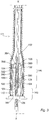
- Figs. 1-3 schematically shows three embodiments of the direct current cable termination apparatus according to the present invention, for terminating a HVDC cable for high voltage (e.g. 10 kV and above, especially 50 kV and above).
- each of the three embodiments of the apparatus comprises a current-carrying device 102, or a voltage-carrying device, comprising a terminal portion 104 of the HVDC cable, the cable at least comprising a central electrical conductor 106, generally made of a suitable metal, e.g.
- the circumferential conductive shield 110 may be made of an electrically conducting polymer.
- the structure of a HVDC cable and its parts, which may comprise further layers, is well known to the skilled person and thus not discussed in more detail herein.
- the HVDC cable may e.g. comprise a so called inner semicon, which is a layer/screen circumferentially surrounding the electrical conductor and being located inside of the insulating layer.
- the inner semicon may be made of an electrically conducting polymer.
- the apparatus comprises a housing 111 comprising a tubular outer shell 112 with an inner periphery 114.
- the outer shell 112 defines a longitudinal axis x-x and is formed by an electrically insulating and polymer-containing material, e.g. a composite.
- the apparatus is substantially rotation symmetric around the axis x-x .
- the outer periphery of the outer shell 112 is provided with sheds 116, or lips/wings, for example made of silicone.
- the current-carrying device 102 is adapted to extend in the axial direction of the outer shell 112.
- the outer shell 112 extends axially with a space 118 between its inner periphery 114 and the outer periphery of current-carrying device 102.
- the housing 111 is adapted to separate the space 118 from an atmosphere outside 120 the outer shell 112.
- a tubular partition 122 which is positioned around the current-carrying device 102, separates the space 118 into a first chamber 124 and a second chamber 126.
- the partition 122 may be made of an electrically insulating and polymer-containing material, for example glass fibre reinforced epoxy.
- the first chamber 124 is filled with an electrically insulating first fluid 125 in the form of an electrically insulating gas, e.g.
- the conductive shield 110 terminates inside the second chamber 126.
- the conductive shield 110 is terminated and forms a termination 109 in the form of a circumferential edge (also called semicon edge).
- the electric field control member 128 may comprise a rubber, polymeric or elastomeric body 129 stretched, or pushed, over the current-carrying device 102, more precisely the terminal portion 104 of the HVDC cable.
- the elastomeric body 129 may be mushroom-shaped.
- the apparatus may also include a plurality of electric field control members, i.e. two or several electric field control members.
- the electric field control member could also be in the form of a linear or non-linear resistive field grading material layer, e.g. in the form of a sleeve made of a non-linear resistive material.
- the electric field control member 128 may comprise a semiconducting, or conductive, layer 130, e.g. made of metal or a polymer material, which in conventional ways may be provided on the lower inner curved periphery of the elastomeric body 129.
- the semiconducting, or conductive, layer 130 may be embedded in the body 129 of the electric field control member 128.
- the semiconducting, or conductive, layer 130 may be formed and composed in various ways known to the skilled person.
- the conductive layer 130 may be called deflector.
- the conductive shield 110 terminates adjacent to the lower part of the electric field control member 128, below, or prior to, the triple point which is formed by the insulating material of the electric field control member 128, the insulating material of the electrically insulating layer 108, and the material of the semiconducting layer 130.
- the second chamber 126 is filled with an electrically insulating second fluid 127 in the form of an electrically insulating gel or an electrically insulating oil, or a mixture thereof.
- the outer shell 112 has a first end portion 132 adjacent to the first chamber 124 and also adjacent to the high voltage side, where the apparatus is connected to e.g. an overhead line or bus bar etc.
- the outer shell 112 has a second end portion 134 adjacent to the second chamber 126.
- the housing 111 may comprise a first flange 138, e.g. made of a metal, at the second end portion 134 of the outer shell 112, and a second flange 152, e.g. made of a metal, at the first end portion 132 of the outer shell 112.
- the HVDC cable enters the outer shell 112 via the second end portion 134 and via a first opening 136 defined by the first flange 138.
- the outer shell 112 extends axially with a gap 140 between its inner periphery 114 and the outer periphery of the partition 122.
- a first part 142 of the terminal portion 104 of the cable has the circumferential conductive shield 110, whereas a remainder part 144 of the terminal portion 104 of the cable has the conductive shield 110 removed, such that the insulating layer 108 is exposed.
- the first part 142 may be called semicon end and the remainder part 144 may be called stripped cable.
- the first part 142, with the conductive shield 110 present, is situated within the second chamber 126 and outside the first chamber 124.
- the current-carrying device 102 includes a connecting body 146 in which the electrical conductor 106 terminates, and the insulating layer 108 may terminate in close proximity of the connecting body 146.
- the connecting body 146 is adapted to electrically connect the terminated electrical conductor 106 to an electrically conducting member 148, here in the form of a rod, for example made of aluminium or copper.
- the conducting member 148 is adapted to extend axially in the first chamber 124 and to form part of the current-carrying device 102.
- the entire connecting body 146 is situated within the first chamber 124 and outside the second chamber 126.
- the conducting member 148 may extend to the outside of the outer shell 112 and exits the outer shell 112 via a second opening 150 defined by the second flange 152. After the exit from the outer shell 112, the conducting member 148 is electrically connected to electric equipment of the high voltage side in conventional ways known to person skilled in the art. Alternatively, the conducting member 148 may be connected to the electric equipment of the high voltage side via the second flange 152, e.g. without exiting the outer shell.
- the partition 122 is thus situated between the connecting body 146 and the second end portion 134 of the outer shell 112, and the second chamber 126 is situated between the connecting body 146 and the second end portion 134 of the outer shell 112.
- the terminal portion 104 of the cable extends from the second end portion 134 of the outer shell 112 to the connecting body 146.
- the partition 112 abuts against the connecting body 146, and the second fluid contained in the second chamber 126 is in physical contact with the connecting body 146.
- the partition 122 of the first embodiment of Fig. 1 forms a truncated cone-shaped inner shell 122 having and defining a first opening 154 at a first end 156 of the inner shell 122, and the first opening 154 seals around the current-carrying device 102, more precisely seals around the terminal portion 104 of the HVDC cable.
- a second open end 158 of the partition 122 is connected in a sealing manner to the first flange 138.
- the partition 122 extends axially with a gap 160 between its inner periphery 162 and an outer surface 164 of the electric field control member 128.
- the partition 122 extends axially with a gap 160 between its inner periphery 162 and the current-carrying device 102.
- the partition 222 of the second embodiment of Fig. 2 forms a cylinder-shaped inner shell 222 having a first basis 223 at a first end 256 of the inner shell 222.
- the first basis 223 is provided with a first opening 254 which seals around the current-carrying device 102, more precisely seals around the terminal portion 104 of the HVDC cable.
- the second embodiment of the apparatus includes a fluid circulation unit 280 connected to the second chamber 126.
- the fluid circulation unit 280 comprises a circuit 282 for circulation of fluid therein, and the second chamber 126 is part of the circuit 282.
- the fluid circulation unit 280 may contain other necessary equipment found in conventional circulation units, for example means for circulating the fluid, e.g. pump means, known to the skilled person.
- the partition 222 of Fig. 2 extends axially with a gap 160 between its inner periphery 262 and the outer surface 164 of the electric field control member 128.
- the partition 322 of the third embodiment of Fig. 3 forms an inner shell 322 having a dome-shaped end portion 356.
- the dome-shaped end portion 356 of the inner shell 322 is provided with a first opening 354, and the first opening 354 seals around the current-carrying device 102, more precisely seals around the terminal portion 104 of the HVDC cable.
- the partition 322 of Fig. 3 extends axially with a gap 160 between its inner periphery 362 and the outer surface 164 of the electric field control member 128.
- the third embodiment of the apparatus includes at least one circumferential field grading material layer 390 which is electrically, and in this embodiment also physically, connected to the conductive shield 110 of the terminal portion 104 of the cable, and is electrically, and in this embodiment also physically, connected to the electrical conductor 106 of the terminal portion 104 of the cable.
- the at least one field grading material layer 390 is herein made of a nonlinear field grading material, FGM, e.g. a resistive field grading material with a field dependent electrical resistivity, e.g. in the form of a SiC or ZnO filler in a suitable polymer base.
- FGM nonlinear field grading material
- the FGM layer 390 has a suitable thickness.
- the at least one FGM layer 390 extends axially and is positioned around the electrical conductor 106 and the electrically insulating layer 108 of the terminal portion 104 of the cable. More precisely, in this embodiment, along the remainder part 144 of the terminal portion 104 of the cable, which has the conductive shield 110 removed, the at least one FGM layer 390 extends axially and is positioned around the electrical conductor 106 and around the electrically insulating layer 108 of the terminal portion 104 of the cable.
- the electric field control member 128 has an inner periphery 166 facing the current-carrying device 102, and the at least one FGM layer 390 is provided such that the electric field control member 128 is positioned around the current-carrying device 102, more precisely around the terminal portion 104 of the cable, with the at least one FGM layer 390 between its inner periphery 166 and outer periphery of the current-carrying device 102.
- the at least one FGM layer 390 may be described as being layer sandwiched between the current-carrying device 102 and the inner periphery 166 of the electric field control member 128.
- the FGM layer 390 may be positioned around or cover the termination of the conductive shield 110, and the FGM layer 390 may also be positioned around or cover at least a portion of the first part 142 of the terminal portion 104 of the cable.
- At least a portion of the outer surface 164 of electric field control member 128, the outer surface 164 facing the partition 322, may also form part of the at least one FGM layer.
- the FGM layer may be applied to the apparatus in various ways, e.g. in the form of a tape wound around the current-carrying device, in the form of a sleeve positioned around the current-carrying device, or in the form a coating or a painted layer applied to the current-carrying device.
- first and second embodiments may be provided with a corresponding FGM layer as shown in Fig. 3
- first and third embodiments may be provided with a fluid circulation unit as shown in Fig. 2
- the second embodiment may have the fluid circulation unit excluded.
- the central electric conductor of the cable could also be terminated outside the outer shell, and thus excluding the connecting body and the conducting member.
Landscapes
- Cable Accessories (AREA)
Claims (15)
- Dispositif de terminaison de câble à courant continu pour la terminaison d'un câble de courant continu à haute tension, le dispositif comprend :un dispositif traversé par un courant (102) comprenant une portion de terminaison (104) du câble de courant continu, le câble comprenant au moins un conducteur électrique (106), une couche d'isolation électrique circonférentielle (108) située à l'extérieur du conducteur électrique et un blindage conducteur circonférentiel (110) situé à l'extérieur de la couche d'isolation du conducteur électrique ;un boîtier (111) comprenant une coque extérieure tubulaire (112) avec une périphérie intérieure (114), la coque extérieure définissant un axe longitudinal (x-x) et étant formée par un matériau électriquement isolant et contenant du polymère ;le dispositif traversé par un courant (102) étant adapté pour s'étendre dans la direction axiale de la coque extérieure,le long d'au moins une partie de l'extension axiale du dispositif traversé par un courant (102), la coque extérieure (112) s'étend axialement avec un espace (118) entre sa périphérie intérieure (114) et le dispositif traversé par un courant,le boîtier (111) est adapté pour séparer l'espace d'une atmosphère à l'extérieur (120) de la coque extérieure, dans lequelle dispositif comprend une partition (122 ;222 ;322) qui sépare l'espace en une première chambre (124) et une seconde chambre (126),la première chambre est remplie avec un premier fluide électriquement isolant (125) et la seconde chambre est remplie avec un second fluide électriquement isolant (127) autre que le premier fluide,le premier fluide comprend un gaz électriquement isolant et le second fluide comprend une matière de remplissage liquide,le blindage conducteur (110) aboutit à l'intérieur de la seconde chambre, etau moins un élément de commande de champ électrique (128) est situé à l'intérieur de la seconde chambre (126) à proximité de et espacé de la terminaison (109) du blindage conducteur (110).
- Dispositif de terminaison de câble à courant continu selon la revendication 1, caractérisé en ce que une première partie (142) de la portion de terminaison (104) du câble possède le blindage conducteur circonférentiel (110), alors que sur une partie restante (144) de la portion de terminaison du câble le blindage conducteur est dénudé, et en ce que la première partie (142) est située à l'intérieur de la seconde chambre extérieure (126) et à l'extérieur de la première chambre (124).
- Dispositif de terminaison de câble à courant continu selon la revendication 1 ou 2, caractérisé en ce que le matériau de remplissage liquide comprend un gel électriquement isolant et/ou une huile électriquement isolante.
- Dispositif de terminaison de câble à courant continu selon une quelconque des revendications 1 à 3, caractérisé en ce que le gaz électriquement isolant comprend du SF6, CO2 et/ou N2.
- Dispositif de terminaison de câble à courant continu selon une quelconque des revendications 1 à 4, caractérisé en ce que le dispositif comprend une unité de mise en circulation de fluide (280) raccordée à la seconde chambre (126), en ce que l'unité de mise en circulation de fluide comprend un circuit (282) pour la mise en circulation du fluide à l'intérieur de ce dernier et en ce que la seconde chambre fait partie du circuit.
- Dispositif de terminaison de câble à courant continu selon une quelconque des revendications 1 à 5, caractérisé en ce que la partition (122 ;222 ;322) est tubulaire et positionnée autour du dispositif traversé par un courant.
- Dispositif de terminaison de câble à courant continu selon une quelconque des revendications 1 à 6, caractérisé en ce que la coque extérieure (112) possède une première portion d'extrémité (132) adjacente à la première chambre (124) et une seconde portion d'extrémité (134) adjacente à la seconde chambre (126), en ce que le dispositif traversé par un courant (102) comprend un corps de raccordement (145) dans lequel le conducteur électrique (106) aboutit, le corps de raccordement étant adapté afin de connecter électriquement le conducteur électrique de terminaison (106) à un élément électriquement conducteur (148) adapté pour s'étendre axialement dans la première chambre (124) et faire partie du dispositif traversé par un courant (102), et en ce que au moins une portion du corps de raccordement (146) est située dans la première chambre.
- Dispositif de terminaison de câble à courant continu selon la revendication 7, caractérisé en ce que la totalité du corps de raccordement (146) est située à l'intérieur de la première chambre (124) et à extérieur de la seconde chambre (126).
- Dispositif de terminaison de câble à courant continu selon une quelconque des revendications 1 à 8, caractérisé en ce que la partition (122 ;222 ;322) est constituée d'un matériau électriquement isolant et contenant du polymère.
- Dispositif de terminaison de câble à courant continu selon une quelconque des revendications 1 à 9, caractérisé en ce que le dispositif comprend au moins une couche de matériau de gradation de champ (390) qui est connectée électriquement au blindage conducteur (110) de la portion de terminaison (104) du câble et peut être connecté électriquement au conducteur électrique (106) de la portion de terminaison du câble, et en ce que le long d'au moins une partie de l'extension axiale du dispositif traversé par un courant (102) à l'intérieur de la seconde chambre (126) au moins une couche de matériau de gradation de champ (390) s'étend actuellement et est positionnée autour d'au moins le conducteur électrique (106) de la portion de terminaison du câble.
- Dispositif de terminaison de câble à courant continu selon la revendication 10, caractérisé en ce que le long d'au moins une partie de l'extension axiale du dispositif traversé par un courant (102) à l'intérieur de la seconde chambre (126) au moins une couche de matériau de gradation de champ (390) est positionnée autour de la couche électriquement isolante (108) de la portion de terminaison (104) du câble.
- Dispositif de terminaison de câble à courant continu selon la revendication 10 ou 11, caractérisé en ce que à l'intérieur de la seconde chambre (126) une première partie (142) de la portion de terminaison du câble possède le blindage électriquement conducteur, alors que sur une partie restante (144) de la portion de terminaison (104) du câble le blindage conducteur (110) est dénudé, et en ce que le long d'au moins la partie restante (144) de la portion de terminaison du câble au moins une couche de matériau de dégradation de champ (390) s'étend actuellement et est positionnée autour d'au moins le conducteur électrique (106) de la portion de terminaison du câble.
- Dispositif de terminaison de câble à courant continu selon la revendication 12, caractérisé en ce que le long de la partie restante (144) de la portion de terminaison (104) du câble au moins une couche de matériau de gradation de champ (390) est positionnée autour de la couche électriquement isolante (108) de la portion de terminaison du câble.
- Dispositif de terminaison de câble à courant continu selon une quelconque des revendications 10 à 13, caractérisé en ce que l'élément de commande de champ électrique (128) possède une périphérie intérieure (166) faisant face au dispositif traversé par un courant (102), et en ce que l'élément de commande de champ électrique (128) est positionné autour du dispositif traversé par un courant (102) avec au moins une couche de matériau de gradation de champ (390) entre sa périphérie intérieure (166) et le dispositif traversé par un courant (102).
- Installation électrique, comprenant un câble de courant à haute tension qui comprend au moins un conducteur électrique (106), une couche isolante circonférentielle (108) située à l'extérieur du conducteur électrique et un blindage conducteur circonférentiel (110) situé à l'extérieur de la couche isolante et du conducteur électrique, et comprenant un dispositif de terminaison de câble à courant continu pour la terminaison du câble, caractérisé ce que le dispositif comprend les fonctionnalités mentionnées dans une quelconque des revendications 1 à 14.
Applications Claiming Priority (1)
| Application Number | Priority Date | Filing Date | Title |
|---|---|---|---|
| PCT/EP2010/057062 WO2011144253A2 (fr) | 2010-05-21 | 2010-05-21 | Appareil de terminaison de câble pour courant continu à haute tension |
Publications (2)
| Publication Number | Publication Date |
|---|---|
| EP2572421A2 EP2572421A2 (fr) | 2013-03-27 |
| EP2572421B1 true EP2572421B1 (fr) | 2019-12-04 |
Family
ID=44624826
Family Applications (1)
| Application Number | Title | Priority Date | Filing Date |
|---|---|---|---|
| EP10720426.5A Active EP2572421B1 (fr) | 2010-05-21 | 2010-05-21 | Appareil de terminaison de câble pour courant continu à haute tension |
Country Status (5)
| Country | Link |
|---|---|
| US (1) | US8946552B2 (fr) |
| EP (1) | EP2572421B1 (fr) |
| CN (1) | CN102906953B (fr) |
| CA (1) | CA2799601C (fr) |
| WO (1) | WO2011144253A2 (fr) |
Families Citing this family (19)
| Publication number | Priority date | Publication date | Assignee | Title |
|---|---|---|---|---|
| EP2572423A2 (fr) * | 2010-05-21 | 2013-03-27 | ABB Research Ltd. | Appareil de terminaison de câble pour courant continu à haute tension |
| CA2940072C (fr) | 2014-02-19 | 2019-09-17 | Abb Schweiz Ag | Dispositif de terminaison de cable d'alimentation pour appareillage de commutation isole au gaz |
| KR102238971B1 (ko) | 2014-02-21 | 2021-04-12 | 엘에스전선 주식회사 | Dc용 케이블의 종단접속함 |
| EP2927923B1 (fr) * | 2014-03-31 | 2017-01-04 | ABB Schweiz AG | Interrupteur de charge de transformateur à sec |
| CN103872636A (zh) * | 2014-04-03 | 2014-06-18 | 上海三原电缆附件有限公司 | 绝缘束接及其在高压直流终端中的应用 |
| EP2980820B1 (fr) * | 2014-08-01 | 2016-09-28 | ABB Schweiz AG | Changeur de prises en charge pour transformateurs secs et lesdits transformateurs |
| CN104535801B (zh) * | 2015-01-12 | 2017-10-31 | 国网上海市电力公司 | 一种用于电缆试验终端的油气混合绝缘装置 |
| DK3148027T3 (da) * | 2015-09-25 | 2020-03-23 | Abb Schweiz Ag | Kabelforskruning til forbindelse af et højspændingskabel til en højspændingskomponent |
| US10704353B2 (en) | 2015-12-22 | 2020-07-07 | Teledyne Instruments, Inc. | Modular electrical feedthrough |
| US9774131B2 (en) | 2015-12-22 | 2017-09-26 | Teledyne Instruments, Inc. | Fire-resistant electrical feedthrough |
| CN106961091A (zh) * | 2016-01-11 | 2017-07-18 | 泰科电子(上海)有限公司 | 电力电缆终端 |
| AU2017414065B2 (en) | 2017-05-11 | 2022-04-21 | Prysmian S.P.A. | Cable termination system, termination assembly and method for installing such a termination assembly |
| US11476614B2 (en) | 2017-05-11 | 2022-10-18 | Prysmian S.P.A. | Cable termination system, termination assembly and method for installing such a termination assembly |
| EP3460177B1 (fr) * | 2017-09-21 | 2021-11-10 | AccessESP UK Limited | Cônes de contrôle de contrainte destinés à des câbles d'alimentation encapsulés dans les tubes d'un système d'alimentation électrique de fond de trou |
| CN108169622B (zh) * | 2017-12-18 | 2021-06-11 | 中国电力科学研究院有限公司 | 直流电缆试验终端 |
| DE102018116416A1 (de) * | 2018-07-06 | 2020-01-09 | Nkt Gmbh & Co. Kg | Verbindungsmuffe |
| IT202000009172A1 (it) | 2020-04-28 | 2021-10-28 | Prysmian Spa | Terminale di cavo ad alta tensione di tipo a secco |
| CN112652912B (zh) * | 2020-12-16 | 2022-12-16 | 迈杰科输配电设备江苏有限公司 | 一种接线端子 |
| EP4024635A1 (fr) | 2020-12-29 | 2022-07-06 | Schneider Electric USA, Inc. | Dispositif de commutation à décharge partielle réduite et présentant des caractéristiques de point triple améliorées |
Citations (3)
| Publication number | Priority date | Publication date | Assignee | Title |
|---|---|---|---|---|
| US4059722A (en) * | 1974-10-12 | 1977-11-22 | Felten & Guilleaume Kabelwerke Aktiengesellschaft | Terminal connector for electrical cables |
| US4783576A (en) * | 1987-10-01 | 1988-11-08 | Pirelli Cable Corporation | High voltage gas filled pipe type cable |
| WO2008119782A1 (fr) * | 2007-03-30 | 2008-10-09 | Abb Research Ltd. | Agencement de terminaison de câble |
Family Cites Families (25)
| Publication number | Priority date | Publication date | Assignee | Title |
|---|---|---|---|---|
| US3439110A (en) * | 1968-06-04 | 1969-04-15 | G & W Electric Speciality Co | Prefabricated stress control shield |
| GB8303462D0 (en) | 1983-02-08 | 1983-03-16 | Raychem Gmbh | Electrical stress control |
| JPS62211813A (ja) * | 1986-03-12 | 1987-09-17 | 三菱電機株式会社 | ガスブツシング |
| DE3822288A1 (de) | 1988-07-01 | 1990-01-04 | Felten & Guilleaume Energie | Verbindungsmuffe fuer vpe-isolierte hoechstspannungskabel |
| EP0571386A4 (fr) * | 1990-08-24 | 1994-10-12 | Electric Power Res Inst | Terminaison de cable electrique a haute tension et a haute intensite comprenant un seul empilement de condensateurs de calibrage. |
| US5130495A (en) * | 1991-01-24 | 1992-07-14 | G & W Electric Company | Cable terminator |
| US5466891A (en) * | 1994-04-08 | 1995-11-14 | Abb Power T&D Company Inc. | Conical composite SF6 high voltage bushing with floating shield |
| GB9600819D0 (en) | 1996-01-16 | 1996-03-20 | Raychem Gmbh | Electrical stress control |
| DE19845006C1 (de) | 1998-10-01 | 2000-04-20 | Felten & Guilleaume Kabelwerk | Oberirdische Kabelverbindung |
| CZ300853B6 (cs) * | 2000-02-09 | 2009-08-26 | Nkt Cables Group Gmbh | Koncovka kabelu |
| JP3744876B2 (ja) * | 2002-04-08 | 2006-02-15 | 昭和電線電纜株式会社 | ポリマー套管およびこれを用いたケーブル終端接続部 |
| SE525492C2 (sv) * | 2002-10-22 | 2005-03-01 | Abb Research Ltd | Fältstyrande polymermatris försedd med fyllning |
| JP2005033930A (ja) * | 2003-07-07 | 2005-02-03 | Exsym Corp | 終端接続部用ストレスコーン |
| FR2867622B1 (fr) | 2004-03-09 | 2006-05-26 | Nexans | Materiau de controle de champ electrique |
| EP1577904B1 (fr) | 2004-03-15 | 2012-02-22 | ABB Research Ltd. | Traversée haute tension avec élément pour les contrôle du champ électrique |
| DE102004046134A1 (de) * | 2004-08-06 | 2006-03-16 | Südkabel GmbH | Freiluftendverschluss |
| EP1736998A1 (fr) | 2005-06-21 | 2006-12-27 | Abb Research Ltd. | Bande à la propriété de varistor pour le contrôle d'un champ électrique |
| BRPI0620938A2 (pt) * | 2005-12-30 | 2011-11-29 | Abb Technology Ag | bucha de alta voltagem e dispositivo de alta voltagem compreendendo esta bucha |
| CN200962512Y (zh) | 2006-05-10 | 2007-10-17 | 3M创新有限公司 | 高压电力电缆终端 |
| DE602006015937D1 (de) | 2006-06-21 | 2010-09-16 | Abb Technology Ltd | Vorrichtung zur elektrischen Feldsteuerung |
| DE102006036233B4 (de) | 2006-08-03 | 2008-03-27 | Nkt Cables Gmbh | Freiluftendverschluss |
| SE531409C2 (sv) | 2006-12-20 | 2009-03-24 | Abb Research Ltd | Fältstyrande material |
| EP2039496A1 (fr) * | 2007-09-20 | 2009-03-25 | ABB Research Ltd. | Procédé de fabrication d'un produit en caoutchouc |
| JP4801182B2 (ja) * | 2008-04-08 | 2011-10-26 | 昭和電線ケーブルシステム株式会社 | ゴムユニットおよびこれを用いたケーブル接続部 |
| EP2026438A1 (fr) | 2008-05-26 | 2009-02-18 | ABB Research LTD | Dispositif de contrôle de champ électrique de connexion de câble et agencement de connexion de câble doté de celui-ci |
-
2010
- 2010-05-21 WO PCT/EP2010/057062 patent/WO2011144253A2/fr not_active Ceased
- 2010-05-21 CA CA2799601A patent/CA2799601C/fr active Active
- 2010-05-21 CN CN201080066921.8A patent/CN102906953B/zh active Active
- 2010-05-21 EP EP10720426.5A patent/EP2572421B1/fr active Active
-
2012
- 2012-11-21 US US13/683,718 patent/US8946552B2/en active Active
Patent Citations (3)
| Publication number | Priority date | Publication date | Assignee | Title |
|---|---|---|---|---|
| US4059722A (en) * | 1974-10-12 | 1977-11-22 | Felten & Guilleaume Kabelwerke Aktiengesellschaft | Terminal connector for electrical cables |
| US4783576A (en) * | 1987-10-01 | 1988-11-08 | Pirelli Cable Corporation | High voltage gas filled pipe type cable |
| WO2008119782A1 (fr) * | 2007-03-30 | 2008-10-09 | Abb Research Ltd. | Agencement de terminaison de câble |
Also Published As
| Publication number | Publication date |
|---|---|
| US8946552B2 (en) | 2015-02-03 |
| US20130075124A1 (en) | 2013-03-28 |
| WO2011144253A2 (fr) | 2011-11-24 |
| CN102906953A (zh) | 2013-01-30 |
| CA2799601C (fr) | 2016-07-05 |
| WO2011144253A3 (fr) | 2012-05-03 |
| CA2799601A1 (fr) | 2011-11-24 |
| CN102906953B (zh) | 2016-04-13 |
| EP2572421A2 (fr) | 2013-03-27 |
Similar Documents
| Publication | Publication Date | Title |
|---|---|---|
| EP2572421B1 (fr) | Appareil de terminaison de câble pour courant continu à haute tension | |
| US8525025B2 (en) | High voltage direct current cable termination apparatus | |
| US8754329B2 (en) | High voltage direct current cable termination apparatus | |
| US10355470B2 (en) | Cable fitting for connecting a high-voltage cable to a high-voltage component | |
| JP5405949B2 (ja) | 2本の高電圧ケーブル間の接続点用装置 | |
| JP4751918B2 (ja) | 気中終端接続部及び気中終端接続部の組立方法 | |
| US8609987B2 (en) | High voltage direct current cable termination apparatus | |
| EP3731361A1 (fr) | Raccord de câble | |
| US11502499B2 (en) | Coupling sleeve | |
| AU2014383641B2 (en) | Power cable termination device for gas-insulated switchgear | |
| JP2018527873A (ja) | 変更ジョイント |
Legal Events
| Date | Code | Title | Description |
|---|---|---|---|
| PUAI | Public reference made under article 153(3) epc to a published international application that has entered the european phase |
Free format text: ORIGINAL CODE: 0009012 |
|
| 17P | Request for examination filed |
Effective date: 20121221 |
|
| AK | Designated contracting states |
Kind code of ref document: A2 Designated state(s): AL AT BE BG CH CY CZ DE DK EE ES FI FR GB GR HR HU IE IS IT LI LT LU LV MC MK MT NL NO PL PT RO SE SI SK SM TR |
|
| DAX | Request for extension of the european patent (deleted) | ||
| 17Q | First examination report despatched |
Effective date: 20140903 |
|
| RAP1 | Party data changed (applicant data changed or rights of an application transferred) |
Owner name: ABB HV CABLES (SWITZERLAND) GMBH |
|
| STAA | Information on the status of an ep patent application or granted ep patent |
Free format text: STATUS: EXAMINATION IS IN PROGRESS |
|
| RAP1 | Party data changed (applicant data changed or rights of an application transferred) |
Owner name: NKT HV CABLES GMBH |
|
| GRAP | Despatch of communication of intention to grant a patent |
Free format text: ORIGINAL CODE: EPIDOSNIGR1 |
|
| STAA | Information on the status of an ep patent application or granted ep patent |
Free format text: STATUS: GRANT OF PATENT IS INTENDED |
|
| INTG | Intention to grant announced |
Effective date: 20190628 |
|
| GRAS | Grant fee paid |
Free format text: ORIGINAL CODE: EPIDOSNIGR3 |
|
| GRAA | (expected) grant |
Free format text: ORIGINAL CODE: 0009210 |
|
| STAA | Information on the status of an ep patent application or granted ep patent |
Free format text: STATUS: THE PATENT HAS BEEN GRANTED |
|
| AK | Designated contracting states |
Kind code of ref document: B1 Designated state(s): AL AT BE BG CH CY CZ DE DK EE ES FI FR GB GR HR HU IE IS IT LI LT LU LV MC MK MT NL NO PL PT RO SE SI SK SM TR |
|
| REG | Reference to a national code |
Ref country code: GB Ref legal event code: FG4D |
|
| RIN1 | Information on inventor provided before grant (corrected) |
Inventor name: SVAHN, JOERGEN Inventor name: UNGE, MIKAEL Inventor name: FORSSEN, CECILIA Inventor name: LI, MING Inventor name: SALTZER, MARKUS Inventor name: GAEFVERT, UNO |
|
| REG | Reference to a national code |
Ref country code: CH Ref legal event code: EP |
|
| REG | Reference to a national code |
Ref country code: AT Ref legal event code: REF Ref document number: 1210612 Country of ref document: AT Kind code of ref document: T Effective date: 20191215 |
|
| REG | Reference to a national code |
Ref country code: DE Ref legal event code: R096 Ref document number: 602010062234 Country of ref document: DE |
|
| REG | Reference to a national code |
Ref country code: IE Ref legal event code: FG4D |
|
| REG | Reference to a national code |
Ref country code: FI Ref legal event code: FGE |
|
| REG | Reference to a national code |
Ref country code: NO Ref legal event code: T2 Effective date: 20191204 |
|
| REG | Reference to a national code |
Ref country code: DE Ref legal event code: R081 Ref document number: 602010062234 Country of ref document: DE Owner name: NKT HV CABLES AB, SE Free format text: FORMER OWNER: NKT HV CABLES GMBH, BADEN, CH |
|
| RAP2 | Party data changed (patent owner data changed or rights of a patent transferred) |
Owner name: NKT HV CABLES AB |
|
| REG | Reference to a national code |
Ref country code: NL Ref legal event code: PD Owner name: NKT HV CABLES AB; SE Free format text: DETAILS ASSIGNMENT: CHANGE OF OWNER(S), ASSIGNMENT; FORMER OWNER NAME: NKT HV CABLES GMBH Effective date: 20200304 |
|
| REG | Reference to a national code |
Ref country code: NL Ref legal event code: FP |
|
| REG | Reference to a national code |
Ref country code: LT Ref legal event code: MG4D |
|
| PG25 | Lapsed in a contracting state [announced via postgrant information from national office to epo] |
Ref country code: LT Free format text: LAPSE BECAUSE OF FAILURE TO SUBMIT A TRANSLATION OF THE DESCRIPTION OR TO PAY THE FEE WITHIN THE PRESCRIBED TIME-LIMIT Effective date: 20191204 Ref country code: LV Free format text: LAPSE BECAUSE OF FAILURE TO SUBMIT A TRANSLATION OF THE DESCRIPTION OR TO PAY THE FEE WITHIN THE PRESCRIBED TIME-LIMIT Effective date: 20191204 Ref country code: SE Free format text: LAPSE BECAUSE OF FAILURE TO SUBMIT A TRANSLATION OF THE DESCRIPTION OR TO PAY THE FEE WITHIN THE PRESCRIBED TIME-LIMIT Effective date: 20191204 Ref country code: BG Free format text: LAPSE BECAUSE OF FAILURE TO SUBMIT A TRANSLATION OF THE DESCRIPTION OR TO PAY THE FEE WITHIN THE PRESCRIBED TIME-LIMIT Effective date: 20200304 Ref country code: ES Free format text: LAPSE BECAUSE OF FAILURE TO SUBMIT A TRANSLATION OF THE DESCRIPTION OR TO PAY THE FEE WITHIN THE PRESCRIBED TIME-LIMIT Effective date: 20191204 |
|
| REG | Reference to a national code |
Ref country code: GR Ref legal event code: EP Ref document number: 20200400589 Country of ref document: GR Effective date: 20200511 |
|
| PG25 | Lapsed in a contracting state [announced via postgrant information from national office to epo] |
Ref country code: HR Free format text: LAPSE BECAUSE OF FAILURE TO SUBMIT A TRANSLATION OF THE DESCRIPTION OR TO PAY THE FEE WITHIN THE PRESCRIBED TIME-LIMIT Effective date: 20191204 |
|
| REG | Reference to a national code |
Ref country code: BE Ref legal event code: PD Owner name: NKT HV CABLES AB; SE Free format text: DETAILS ASSIGNMENT: CHANGE OF OWNER(S), CESSION; FORMER OWNER NAME: NKT HV CABLES GMBH Effective date: 20200410 |
|
| PG25 | Lapsed in a contracting state [announced via postgrant information from national office to epo] |
Ref country code: AL Free format text: LAPSE BECAUSE OF FAILURE TO SUBMIT A TRANSLATION OF THE DESCRIPTION OR TO PAY THE FEE WITHIN THE PRESCRIBED TIME-LIMIT Effective date: 20191204 |
|
| PG25 | Lapsed in a contracting state [announced via postgrant information from national office to epo] |
Ref country code: PT Free format text: LAPSE BECAUSE OF FAILURE TO SUBMIT A TRANSLATION OF THE DESCRIPTION OR TO PAY THE FEE WITHIN THE PRESCRIBED TIME-LIMIT Effective date: 20200429 Ref country code: RO Free format text: LAPSE BECAUSE OF FAILURE TO SUBMIT A TRANSLATION OF THE DESCRIPTION OR TO PAY THE FEE WITHIN THE PRESCRIBED TIME-LIMIT Effective date: 20191204 Ref country code: CZ Free format text: LAPSE BECAUSE OF FAILURE TO SUBMIT A TRANSLATION OF THE DESCRIPTION OR TO PAY THE FEE WITHIN THE PRESCRIBED TIME-LIMIT Effective date: 20191204 Ref country code: EE Free format text: LAPSE BECAUSE OF FAILURE TO SUBMIT A TRANSLATION OF THE DESCRIPTION OR TO PAY THE FEE WITHIN THE PRESCRIBED TIME-LIMIT Effective date: 20191204 |
|
| PG25 | Lapsed in a contracting state [announced via postgrant information from national office to epo] |
Ref country code: SM Free format text: LAPSE BECAUSE OF FAILURE TO SUBMIT A TRANSLATION OF THE DESCRIPTION OR TO PAY THE FEE WITHIN THE PRESCRIBED TIME-LIMIT Effective date: 20191204 Ref country code: SK Free format text: LAPSE BECAUSE OF FAILURE TO SUBMIT A TRANSLATION OF THE DESCRIPTION OR TO PAY THE FEE WITHIN THE PRESCRIBED TIME-LIMIT Effective date: 20191204 Ref country code: IS Free format text: LAPSE BECAUSE OF FAILURE TO SUBMIT A TRANSLATION OF THE DESCRIPTION OR TO PAY THE FEE WITHIN THE PRESCRIBED TIME-LIMIT Effective date: 20200404 |
|
| REG | Reference to a national code |
Ref country code: DE Ref legal event code: R097 Ref document number: 602010062234 Country of ref document: DE |
|
| REG | Reference to a national code |
Ref country code: AT Ref legal event code: MK05 Ref document number: 1210612 Country of ref document: AT Kind code of ref document: T Effective date: 20191204 |
|
| PLBE | No opposition filed within time limit |
Free format text: ORIGINAL CODE: 0009261 |
|
| STAA | Information on the status of an ep patent application or granted ep patent |
Free format text: STATUS: NO OPPOSITION FILED WITHIN TIME LIMIT |
|
| PG25 | Lapsed in a contracting state [announced via postgrant information from national office to epo] |
Ref country code: DK Free format text: LAPSE BECAUSE OF FAILURE TO SUBMIT A TRANSLATION OF THE DESCRIPTION OR TO PAY THE FEE WITHIN THE PRESCRIBED TIME-LIMIT Effective date: 20191204 |
|
| 26N | No opposition filed |
Effective date: 20200907 |
|
| PG25 | Lapsed in a contracting state [announced via postgrant information from national office to epo] |
Ref country code: AT Free format text: LAPSE BECAUSE OF FAILURE TO SUBMIT A TRANSLATION OF THE DESCRIPTION OR TO PAY THE FEE WITHIN THE PRESCRIBED TIME-LIMIT Effective date: 20191204 Ref country code: SI Free format text: LAPSE BECAUSE OF FAILURE TO SUBMIT A TRANSLATION OF THE DESCRIPTION OR TO PAY THE FEE WITHIN THE PRESCRIBED TIME-LIMIT Effective date: 20191204 Ref country code: PL Free format text: LAPSE BECAUSE OF FAILURE TO SUBMIT A TRANSLATION OF THE DESCRIPTION OR TO PAY THE FEE WITHIN THE PRESCRIBED TIME-LIMIT Effective date: 20191204 |
|
| PG25 | Lapsed in a contracting state [announced via postgrant information from national office to epo] |
Ref country code: LI Free format text: LAPSE BECAUSE OF NON-PAYMENT OF DUE FEES Effective date: 20200531 Ref country code: CH Free format text: LAPSE BECAUSE OF NON-PAYMENT OF DUE FEES Effective date: 20200531 Ref country code: MC Free format text: LAPSE BECAUSE OF FAILURE TO SUBMIT A TRANSLATION OF THE DESCRIPTION OR TO PAY THE FEE WITHIN THE PRESCRIBED TIME-LIMIT Effective date: 20191204 |
|
| GBPC | Gb: european patent ceased through non-payment of renewal fee |
Effective date: 20200521 |
|
| PG25 | Lapsed in a contracting state [announced via postgrant information from national office to epo] |
Ref country code: LU Free format text: LAPSE BECAUSE OF NON-PAYMENT OF DUE FEES Effective date: 20200521 |
|
| PG25 | Lapsed in a contracting state [announced via postgrant information from national office to epo] |
Ref country code: GB Free format text: LAPSE BECAUSE OF NON-PAYMENT OF DUE FEES Effective date: 20200521 Ref country code: IE Free format text: LAPSE BECAUSE OF NON-PAYMENT OF DUE FEES Effective date: 20200521 |
|
| PG25 | Lapsed in a contracting state [announced via postgrant information from national office to epo] |
Ref country code: TR Free format text: LAPSE BECAUSE OF FAILURE TO SUBMIT A TRANSLATION OF THE DESCRIPTION OR TO PAY THE FEE WITHIN THE PRESCRIBED TIME-LIMIT Effective date: 20191204 Ref country code: MT Free format text: LAPSE BECAUSE OF FAILURE TO SUBMIT A TRANSLATION OF THE DESCRIPTION OR TO PAY THE FEE WITHIN THE PRESCRIBED TIME-LIMIT Effective date: 20191204 Ref country code: CY Free format text: LAPSE BECAUSE OF FAILURE TO SUBMIT A TRANSLATION OF THE DESCRIPTION OR TO PAY THE FEE WITHIN THE PRESCRIBED TIME-LIMIT Effective date: 20191204 |
|
| PG25 | Lapsed in a contracting state [announced via postgrant information from national office to epo] |
Ref country code: MK Free format text: LAPSE BECAUSE OF FAILURE TO SUBMIT A TRANSLATION OF THE DESCRIPTION OR TO PAY THE FEE WITHIN THE PRESCRIBED TIME-LIMIT Effective date: 20191204 |
|
| P01 | Opt-out of the competence of the unified patent court (upc) registered |
Effective date: 20230527 |
|
| PGFP | Annual fee paid to national office [announced via postgrant information from national office to epo] |
Ref country code: NL Payment date: 20250522 Year of fee payment: 16 |
|
| PGFP | Annual fee paid to national office [announced via postgrant information from national office to epo] |
Ref country code: FI Payment date: 20250515 Year of fee payment: 16 |
|
| PGFP | Annual fee paid to national office [announced via postgrant information from national office to epo] |
Ref country code: DE Payment date: 20250520 Year of fee payment: 16 |
|
| PGFP | Annual fee paid to national office [announced via postgrant information from national office to epo] |
Ref country code: NO Payment date: 20250519 Year of fee payment: 16 |
|
| PGFP | Annual fee paid to national office [announced via postgrant information from national office to epo] |
Ref country code: BE Payment date: 20250522 Year of fee payment: 16 Ref country code: IT Payment date: 20250520 Year of fee payment: 16 |
|
| PGFP | Annual fee paid to national office [announced via postgrant information from national office to epo] |
Ref country code: FR Payment date: 20250516 Year of fee payment: 16 |
|
| PGFP | Annual fee paid to national office [announced via postgrant information from national office to epo] |
Ref country code: GR Payment date: 20250521 Year of fee payment: 16 |