EP2572637A2 - Dispositif pour l'examen de la fonction nerveuse - Google Patents
Dispositif pour l'examen de la fonction nerveuse Download PDFInfo
- Publication number
- EP2572637A2 EP2572637A2 EP11783689A EP11783689A EP2572637A2 EP 2572637 A2 EP2572637 A2 EP 2572637A2 EP 11783689 A EP11783689 A EP 11783689A EP 11783689 A EP11783689 A EP 11783689A EP 2572637 A2 EP2572637 A2 EP 2572637A2
- Authority
- EP
- European Patent Office
- Prior art keywords
- stimulator
- fixing member
- human body
- skin
- feet
- Prior art date
- Legal status (The legal status is an assumption and is not a legal conclusion. Google has not performed a legal analysis and makes no representation as to the accuracy of the status listed.)
- Withdrawn
Links
Images


Classifications
-
- A—HUMAN NECESSITIES
- A61—MEDICAL OR VETERINARY SCIENCE; HYGIENE
- A61B—DIAGNOSIS; SURGERY; IDENTIFICATION
- A61B5/00—Measuring for diagnostic purposes; Identification of persons
- A61B5/40—Detecting, measuring or recording for evaluating the nervous system
- A61B5/4005—Detecting, measuring or recording for evaluating the nervous system for evaluating the sensory system
-
- A—HUMAN NECESSITIES
- A61—MEDICAL OR VETERINARY SCIENCE; HYGIENE
- A61B—DIAGNOSIS; SURGERY; IDENTIFICATION
- A61B5/00—Measuring for diagnostic purposes; Identification of persons
- A61B5/48—Other medical applications
- A61B5/4824—Touch or pain perception evaluation
- A61B5/4827—Touch or pain perception evaluation assessing touch sensitivity, e.g. for evaluation of pain threshold
-
- A—HUMAN NECESSITIES
- A43—FOOTWEAR
- A43B—CHARACTERISTIC FEATURES OF FOOTWEAR; PARTS OF FOOTWEAR
- A43B3/00—Footwear characterised by the shape or the use
- A43B3/34—Footwear characterised by the shape or the use with electrical or electronic arrangements
- A43B3/35—Footwear characterised by the shape or the use with electrical or electronic arrangements with electric heating arrangements
- A43B3/355—Footwear characterised by the shape or the use with electrical or electronic arrangements with electric heating arrangements heated by an electric current from an external source, e.g. car batteries
-
- A—HUMAN NECESSITIES
- A43—FOOTWEAR
- A43B—CHARACTERISTIC FEATURES OF FOOTWEAR; PARTS OF FOOTWEAR
- A43B3/00—Footwear characterised by the shape or the use
- A43B3/34—Footwear characterised by the shape or the use with electrical or electronic arrangements
- A43B3/38—Footwear characterised by the shape or the use with electrical or electronic arrangements with power sources
-
- A—HUMAN NECESSITIES
- A43—FOOTWEAR
- A43B—CHARACTERISTIC FEATURES OF FOOTWEAR; PARTS OF FOOTWEAR
- A43B7/00—Footwear with health or hygienic arrangements
- A43B7/14—Footwear with health or hygienic arrangements with foot-supporting parts
- A43B7/1405—Footwear with health or hygienic arrangements with foot-supporting parts with pads or holes on one or more locations, or having an anatomical or curved form
- A43B7/1455—Footwear with health or hygienic arrangements with foot-supporting parts with pads or holes on one or more locations, or having an anatomical or curved form with special properties
- A43B7/146—Footwear with health or hygienic arrangements with foot-supporting parts with pads or holes on one or more locations, or having an anatomical or curved form with special properties provided with acupressure points or means for foot massage
-
- A—HUMAN NECESSITIES
- A43—FOOTWEAR
- A43B—CHARACTERISTIC FEATURES OF FOOTWEAR; PARTS OF FOOTWEAR
- A43B7/00—Footwear with health or hygienic arrangements
- A43B7/14—Footwear with health or hygienic arrangements with foot-supporting parts
- A43B7/1405—Footwear with health or hygienic arrangements with foot-supporting parts with pads or holes on one or more locations, or having an anatomical or curved form
- A43B7/1455—Footwear with health or hygienic arrangements with foot-supporting parts with pads or holes on one or more locations, or having an anatomical or curved form with special properties
- A43B7/147—Footwear with health or hygienic arrangements with foot-supporting parts with pads or holes on one or more locations, or having an anatomical or curved form with special properties for sick or disabled persons, e.g. persons having osteoarthritis or diabetes
-
- A—HUMAN NECESSITIES
- A61—MEDICAL OR VETERINARY SCIENCE; HYGIENE
- A61B—DIAGNOSIS; SURGERY; IDENTIFICATION
- A61B5/00—Measuring for diagnostic purposes; Identification of persons
- A61B5/01—Measuring temperature of body parts ; Diagnostic temperature sensing, e.g. for malignant or inflamed tissue
-
- A—HUMAN NECESSITIES
- A61—MEDICAL OR VETERINARY SCIENCE; HYGIENE
- A61B—DIAGNOSIS; SURGERY; IDENTIFICATION
- A61B5/00—Measuring for diagnostic purposes; Identification of persons
- A61B5/02—Detecting, measuring or recording for evaluating the cardiovascular system, e.g. pulse, heart rate, blood pressure or blood flow
- A61B5/0205—Simultaneously evaluating both cardiovascular conditions and different types of body conditions, e.g. heart and respiratory condition
-
- A—HUMAN NECESSITIES
- A61—MEDICAL OR VETERINARY SCIENCE; HYGIENE
- A61B—DIAGNOSIS; SURGERY; IDENTIFICATION
- A61B5/00—Measuring for diagnostic purposes; Identification of persons
- A61B5/02—Detecting, measuring or recording for evaluating the cardiovascular system, e.g. pulse, heart rate, blood pressure or blood flow
- A61B5/026—Measuring blood flow
-
- A—HUMAN NECESSITIES
- A61—MEDICAL OR VETERINARY SCIENCE; HYGIENE
- A61B—DIAGNOSIS; SURGERY; IDENTIFICATION
- A61B5/00—Measuring for diagnostic purposes; Identification of persons
- A61B5/145—Measuring characteristics of blood in vivo, e.g. gas concentration or pH-value ; Measuring characteristics of body fluids or tissues, e.g. interstitial fluid or cerebral tissue
- A61B5/1455—Measuring characteristics of blood in vivo, e.g. gas concentration or pH-value ; Measuring characteristics of body fluids or tissues, e.g. interstitial fluid or cerebral tissue using optical sensors, e.g. spectral photometrical oximeters
- A61B5/14551—Measuring characteristics of blood in vivo, e.g. gas concentration or pH-value ; Measuring characteristics of body fluids or tissues, e.g. interstitial fluid or cerebral tissue using optical sensors, e.g. spectral photometrical oximeters for measuring blood gases
-
- A—HUMAN NECESSITIES
- A61—MEDICAL OR VETERINARY SCIENCE; HYGIENE
- A61B—DIAGNOSIS; SURGERY; IDENTIFICATION
- A61B5/00—Measuring for diagnostic purposes; Identification of persons
- A61B5/40—Detecting, measuring or recording for evaluating the nervous system
- A61B5/4029—Detecting, measuring or recording for evaluating the nervous system for evaluating the peripheral nervous systems
- A61B5/4041—Evaluating nerves condition
- A61B5/4047—Evaluating nerves condition afferent nerves, i.e. nerves that relay impulses to the central nervous system
-
- A—HUMAN NECESSITIES
- A61—MEDICAL OR VETERINARY SCIENCE; HYGIENE
- A61B—DIAGNOSIS; SURGERY; IDENTIFICATION
- A61B5/00—Measuring for diagnostic purposes; Identification of persons
- A61B5/48—Other medical applications
- A61B5/4824—Touch or pain perception evaluation
- A61B5/4827—Touch or pain perception evaluation assessing touch sensitivity, e.g. for evaluation of pain threshold
- A61B5/483—Touch or pain perception evaluation assessing touch sensitivity, e.g. for evaluation of pain threshold by thermal stimulation
-
- A—HUMAN NECESSITIES
- A61—MEDICAL OR VETERINARY SCIENCE; HYGIENE
- A61B—DIAGNOSIS; SURGERY; IDENTIFICATION
- A61B5/00—Measuring for diagnostic purposes; Identification of persons
- A61B5/68—Arrangements of detecting, measuring or recording means, e.g. sensors, in relation to patient
- A61B5/6801—Arrangements of detecting, measuring or recording means, e.g. sensors, in relation to patient specially adapted to be attached to or worn on the body surface
- A61B5/6802—Sensor mounted on worn items
- A61B5/6804—Garments; Clothes
- A61B5/6806—Gloves
-
- A—HUMAN NECESSITIES
- A61—MEDICAL OR VETERINARY SCIENCE; HYGIENE
- A61B—DIAGNOSIS; SURGERY; IDENTIFICATION
- A61B5/00—Measuring for diagnostic purposes; Identification of persons
- A61B5/68—Arrangements of detecting, measuring or recording means, e.g. sensors, in relation to patient
- A61B5/6801—Arrangements of detecting, measuring or recording means, e.g. sensors, in relation to patient specially adapted to be attached to or worn on the body surface
- A61B5/6802—Sensor mounted on worn items
- A61B5/6804—Garments; Clothes
- A61B5/6807—Footwear
-
- A—HUMAN NECESSITIES
- A61—MEDICAL OR VETERINARY SCIENCE; HYGIENE
- A61B—DIAGNOSIS; SURGERY; IDENTIFICATION
- A61B5/00—Measuring for diagnostic purposes; Identification of persons
- A61B5/68—Arrangements of detecting, measuring or recording means, e.g. sensors, in relation to patient
- A61B5/6801—Arrangements of detecting, measuring or recording means, e.g. sensors, in relation to patient specially adapted to be attached to or worn on the body surface
- A61B5/6813—Specially adapted to be attached to a specific body part
- A61B5/6825—Hand
-
- A—HUMAN NECESSITIES
- A61—MEDICAL OR VETERINARY SCIENCE; HYGIENE
- A61B—DIAGNOSIS; SURGERY; IDENTIFICATION
- A61B5/00—Measuring for diagnostic purposes; Identification of persons
- A61B5/68—Arrangements of detecting, measuring or recording means, e.g. sensors, in relation to patient
- A61B5/6801—Arrangements of detecting, measuring or recording means, e.g. sensors, in relation to patient specially adapted to be attached to or worn on the body surface
- A61B5/6813—Specially adapted to be attached to a specific body part
- A61B5/6829—Foot or ankle
Definitions
- the present invention relates to a device for examining nerve function, and more specifically, to a device for examining nerve function which examines a sensation in the hands or the feet of a subject such as a patient having diabetes or spinal nerve damage, so as to check a disease condition, to prevent an accident, and to treat the disease.
- diabetes is a disease in which cells are unable to absorb sugars entered into the body and the blood sugar level increases, either because an enough amount of insulin that the body requires is not produced, or because the produced insulin does not work properly in the cells.
- the diabetes may lead to serious complications, for example complications in large blood vessels or small blood vessels developed from hardening of the arteries in blood vessels. This may cause renal failure and require long-term hemodialysis, or cause a coronary or cerebrovascular disorder or retinal damage, and even cause necrosis of the foot due to blood supply shortage.
- hypoesthesia first occurs in the feet in which blood circulation is not performed smoothly. Unless properly treating or preventing this, small blood vessels in the toes would be blocked and as a result the situation that the toes get rotten may occur.
- an object of the present invention is to provide a device for examining nerve function capable of: greatly improving accuracy and reliability of the examination using a standardized stimulator and a standardized stimulator fixing member; expressing as a number the degree of hypoesthesia or the status of hypoesthesia through the examination for the patient's nerve function; exactly determining the specific position of the patients' hypoesthesia so as to systematically and actively determine a diagnosis and treatment course for the patients having hypoesthesia for example those suffering diabetes; and especially detecting the state of blood circulation to check the position of hypoesthesia.
- Another object of the present invention is to provide a device for examining nerve function capable of: accurately adjusting the degree of stimulation by automatically moving a pressurizer having an actuator; and recording and checking the degree of hypoesthesia in real time and for a long period of time with a subject wearing an elastic clothing, stimulation gloves or stimulation boots in practical life.
- another object of the present invention is to provide a device for examining nerve function capable of: checking if a subject can feel pain caused by applying pressure, and if a subject can distinguish positions among multiple pressure points (positions of pressure points), and if a subject can detect vibration, if a subject can detect change in temperature, and if a subject can distinguish difference in the applied pressure, through the pain caused by the applied pressure; and checking the state of blood circulation through oxygen saturation or temperature of the hypoesthesia area.
- the present invention aims to provide a device for examining nerve function capable of not only proceeding with the process of measuring the above-mentioned capabilities step by step but also reviewing the measured capabilities and the state of blood circulation in an audio or video message or in a printed material.
- the device for examining nerve function includes at least one stimulator for stimulating the human body to examine nerve function in the human body; and a stimulator fixing member formed in the shape corresponding to the hands or the feet of the human body, in which the stimulator is located at one side of the stimulator fixing member so as to fix the hands or the feet of the human body.
- the stimulator may include at least one of a pressurizer for pressurizing the skin to provide stimulation and a vibrator for applying vibration-type stimulation to the skin.
- the pressurizer may include a hollow holder fixed at one side of the stimulator fixing member; and a stimulating pin inserted into a hollow which is formed inside the hollow holder and moving forward and backward in the hollow, in which the front end portion is moved to pressurize the skin to provide stimulation, and the back end portion may include a pressing unit or an actuator.
- the pressurizer may further include a raised portion formed on the stimulating pin to move together with the stimulating pin; and a stopper formed in the hollow, in which the raised portion is blocked by the stopper.
- the stimulator may include a hollow holder fixed at one side of the stimulator fixing member and having multiple hollows; and at least one stimulating pin inserted into a hollow that is formed inside the hollow holder and moving forward and backward in the hollow, in which the front end portion is moved to pressurize the skin to provide stimulation and the back end portion may include a pressing unit or an actuator.
- the stimulator may further include a holder fixing member for rotatably fixing the hollow holder to the simulator fixing member.
- the holder fixing member is integrally fixed to the simulator fixing member and may include a fixing ring having an inner circumferential surface so as to allow the hollow holder to be fitted to the fixing ring.
- the stimulator may include a toe moving member for moving the position of the toe to stimulate the toe.
- the toe moving member may include a lift for lifting the toe of the feet; and an elevator for elevating the lift.
- the stimulator may include an electric heater for applying heat to the skin to stimulate the skin.
- the present invention may further include at least one blood circulation detecting sensor placed on the stimulator fixing member for detecting blood circulation of the human body.
- the blood circulation detecting sensor may include at least one of an oxygen saturation sensor for measuring oxygen saturation in the blood inside the skin and a temperature measuring sensor for measuring skin temperature.
- the simulator fixing member may include an elastic clothing that is wearable on the hands or feet of the human body.
- the simulator fixing member may include a fixing frame corresponding to the hands or feet of the human body.
- the fixing frame may include a supporting plate for supporting the hands or feet of the human body; and a first extendable rod extending to the upward direction of the supporting plate, inwhich the stimulator is integrally fixed to the first extendable rod.
- the fixing frame may include a supporting plate for supporting the hands or feet of the human body; a first extendable rod extending to the upward direction of the supporting plate; a second extendable rod extending to the different direction from the first extendable rod and having the stimulator at the front end portion; and a joint for fixing the second extendable rod to the first extendable rod.
- the simulator fixing member may further include a stimulator movement rail for guiding the path of movement of the stimulator.
- the stimulator movement rail may have a rail groove corresponding to a protrusion formed on one side of the stimulator.
- the present invention includes: a stimulator for stimulating the human body to examine nerve function of the human body, having at least one of a pressurizer for pressurizing the skin to provide stimulation, a vibrator for applying vibration-type stimulation to the skin, a toe moving member for moving the position of the toe to stimulate the toe, and an electric heater for applying heat to the skin to stimulate the skin; a stimulator fixing member formed in the shape corresponding to the hands or feet of the human body, in which the stimulator is located at one side so as to fix the stimulator to the hands or feet of the human body; a blood circulation detecting sensor for detecting blood circulation of the human body, placed on the stimulator fixing member and having at least one of an oxygen saturation sensor for measuring oxygen saturation in the blood inside the skin and a temperature measuring sensor for measuring skin temperature; a confirmation button operated by a subject to produce a confirmation signal which confirms that the skin or the toe has been stimulated by the stimulator; a terminal for setting a sequential measurement process by comparing a pre-set stepwise
- the device for examining nerve function has the following effects: significantly improving precision and reliability of examinations for nerve function; and systemically and actively determining an exact diagnosis for patients having hypoesthesia with the symptoms of diabetes or spinal nerve damage; also exactly diagnosing the area of chronic neurological complications, and accurately adjusting the degree of stimulation; and recording and checking the degree of hypoesthesia in real time and for a long period of time with a subject wearing an elastic clothing, stimulation gloves or stimulation boots in practical life.
- the device is capable of: checking if a subject can feel pain caused by applying pressure, and if a subject can distinguish positions between two pressure points (positions of two areas), and if a subject can detect vibration, if a subject can detect change in temperature, and if a subject can distinguish difference in the applied pressure, through the pain caused by the applied pressure; and checking the degree of hypoesthesia by screening the state of blood circulation through oxygen saturation or temperature of the hypoesthesia area.
- the device is capable of not only guiding the stepwise process of measuring the capabilities by voice or display, it is possible to not only perform examinations with ease, but also to see the measured capabilities and the state of blood circulation in an audio or video message, or in a printed material so as to understand the degree of hypoesthesia with ease.
- FIG. 1 is a cross-sectional view illustrating a device for examining nerve function according to the first embodiment of the present invention.
- FIG. 2 is a cross-sectional view illustrating an example of the pressurizer illustrated in FIG. 1 .
- FIG. 3 is a cross-sectional view illustrating an example of the vibrator illustrated in FIG. 1 .
- FIG. 4 is a cross-sectional view illustrating an example of the movement rail illustrated in FIG. 1 .
- FIG. 5 is a cross-sectional view illustrating a device for examining nerve function according to the second embodiment of the present invention.
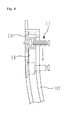
- FIG. 6 is a cross-sectional view illustrating a first extendable rod, a second extendable rod and a joint of FIG. 5 .
- FIG. 7 is a cross-sectional view illustrating a device for examining nerve function according to the third embodiment of the present invention.
- FIG. 8 is a cross-sectional view illustrating a device for examining nerve function according to the fourth embodiment of the present invention.
- FIG. 9 is a cross-sectional view illustrating a device for examining nerve function according to the fifth embodiment of the present invention.
- FIG. 10 is a cross-sectional view illustrating a device for examining nerve function according to the sixth embodiment of the present invention.
- FIG. 11 is a cross-sectional view illustrating a device for examining nerve function according to the seventh embodiment of the present invention.
- FIG. 12 is a cross-sectional view illustrating a device for examining nerve function according to the eighth embodiment of the present invention.
- the device for examining nerve function may include a stimulator 10 and a stimulator fixing member 20, as shown in FIGs. 1 to 4 .
- the stimulator 10 which generates stimulation on the human body in order to examine nerve function of the human body, includes a pressurizer 11 for pressurizing the skin with a stick-type stimulating pin 112 as shown in FIG. 2 and/or a vibrator 12 for applying vibration to the skin that comes into contact with a vibration surface 112 with a vibration motor 121 as shown in FIG. 3 .
- the pressurizer 11 may include a hollow holder 111 and a stimulating pin 112 as shown in FIG. 2 .
- the hollow holder 111 is fixed at one side of an elastic clothing 21, which is a kind of stimulator fixing member 20, and multiple hollow holders may be provided, for example at an important stimulation point such as a meridian point, at a main check point representing a long distance from the heart, or at a position representing a certain distance from the toes.
- the stimulating pin 112 may be made of wood or of a monofilament of plastic material or nylon material. Such a stimulating pin 112 is inserted into a hollow 111a that is formed inside the hollow holder 111 in such a manner so as to be movable forward and backward.
- the stimulating pin 112 may has a blunt front end portion, but it is rather preferable to form an actuate stimulation point 112a.
- the back end portion may preferably include a pressing unit 112b or an actuator 13 for enabling forward and backward movement of the stimulating pin 112 in a selective manner.
- Such an actuator 13 can be configured to adjust the movement distance of the stimulating pin 112 which moves forward and backward depending on the magnitude of supplied voltage.
- inspectors may therefore check an accurate response from the subject's response when considering the numerical stimulation that is expressed in a certain distance from the toes of the subject, i.e. the length of forward movement of the stimulating pin 112 that is moved forward by the actuator 113.
- the device is capable of automatically and numerically measuring how much the symptoms of hypoesthesia have improved or deteriorated.
- the movement distance of the stimulating pin 112 is adjusted by the actuator 113, it is able to adjust the strength of the contact of the stimulating pin 112, thereby precisely checking the sensory reaction from the subject.
- the stimulating pin 112 described above may be connected to a sensor for detecting the movement distance when moving forward and backward, which is not illustrated. It is preferable that such a sensor is placed in the hollow holder 111 and may include a normal optical sensor or hall sensor. Those skilled in the art could easily understand the configuration of such a sensor, and thus its detailed description will be omitted.
- multiple pressurizers 11 may be provided with one adjacent to another and with one separated from another. These pressurizers 11 individually pressurize the skin in a state where they are separated from one another. In other words, the pressurizers 11 individually pressurize two areas at the same time. Therefore, the subject may check whether to distinguish two stimulation points at which the stimulation occurs. That is, if the subject is unable to distinguish two stimulation points, it may be determined that the sensation has been reduced at the areas corresponding to the stimulation points.
- a raised portion 112c may be formed on the stimulating pin 112 so as to prevent the stimulating pin 112 that moves inside the hollow holder 111 from moving away from the hollow holder 111 as shown in FIG. 2 , and a stopper 111b may be formed in the hollow 111a. That is, the raised portion 112c is blocked by the stopper 111b and thereby restricting the forward/backward distance of the stimulating pin 112.
- the hollow holder 111 described above, as illustrated, may be integrally fixed to the stimulator fixing member 20 via a movement rail 40, which will be described below.
- the hollow holder 111 may be indirectly fixed to the stimulator fixing member 20.
- Such a hollow holder 111 may be fixed to the movement rail 40 in a detachable manner by bolting, and it may also be permanently fixed to the movement rail 40 by welding or bonding.
- the hollow holder 111 may be directly fixed to the stimulator fixing member 20.
- the hollow holder 111 is directly connected to the stimulator fixing member 20 by bolting or bonding.
- the stimulator fixing member 20 is the elastic clothing 21 described above
- the hollow holder 111 may be fixed to the elastic clothing 21 by bonding, or fixed to the elastic clothing 21 by bolting using an bracket, which is not illustrated.
- the vibrator described above is fixed to the stimulator fixing member 20, the movement rail 40 or the elastic clothing 21 in the same way as the hollow holder 111.
- Those skilled in the art could easily carry out the method of fixing such a hollow holder 111 and a vibrator 12, and thus its detailed description will be omitted
- the stimulator fixing member 20 may include multiple pressurizers 11 and multiple vibrators 12 at one side to fix the stimulator 10 to the hands 1 or the feet 2 of the human body, and it is formed in the shape corresponding to the feet 2 of the human body, and it may also include the elastic clothing 21 which is wearable on the feet 2.
- the elastic clothing 21 may include either a socks-type item of clothing or a stocking-type item of clothing, as shown in FIG. 1 .
- the subject when using the device for examining nerve function according to the present invention, the subject may move in a state where the subject is wearing the elastic clothing 21 and at the same time check the degree of hypoesthesia by receiving various types of stimulation such as pressure or vibration.
- the device for examining nerve function may further include a blood circulation detecting sensor 30 for detecting blood circulation of the human body, which is placed on the stimulator fixing member 20.
- the blood circulation detecting sensor 30, which is a sensor for detecting blood circulation of the human body, may include an oxygen saturation sensor 31 for measuring oxygen saturation in the blood inside the skin and/or a temperature measuring sensor 32 for measuring skin temperature, as shown in FIG. 1 .
- the subject when using the device for examining nerve function according to the present invention, the subject may move in a state where the subject is wearing the elastic clothing 21 and at the same time check the patient's nerve function by measuring oxygen saturation in the blood circulating in the feet or feet temperature.
- a stimulator movement rail 40 on the stimulator fixing member 20 for guiding the path of movement of the stimulator 10 so as to reduce the number of pressurizers 11 or vibrators 12 arranged on the feet of the subject and to provide stimulation to one point or to some points contiously, as shown in FIG. 4 .
- the stimulator movement rail 40 has a rail groove 41 formed to correspond to a protrusion 13 that is formed on one side of the pressurizer 11 or the vibrator 12 as shown in FIG. 4 , so that the pressurizer 11 or the vibrator 12 could apply stimulation to specific points or to a specific point or to some points continuously moving along the rail groove 41.
- the stimulator movement rail 40 may be provided on sensitive boots 23, which will be described below, and in this case, a scaled ruler 224 may be placed at one side so as to measure the movement distance, height, etc. of the stimulator 10.
- the device for examining nerve function may include a fixing frame 22 corresponding to the feet 2 of the human body, as a kind of stimulator fixing member 20.
- the fixing frame 22 includes a supporting plate 220, a first extendable rod 221, a second extendable rod 222 and a joint 223, as shown in FIG. 5 .
- the supporting plate 220 supports the feet 2 of the human body.
- the oxygen saturation sensor 31 and the temperature measuring sensor 32 placed on the supporting plate 220 may check blood condition of the patent's feet.
- the oxygen saturation sensor 31 and the temperature measuring sensor 32 of the supporting plate 220 may also be placed at the first extendable rod 221 so that they may operate above the supporting plate 220, as marked in a broken line in the figure. That is, the oxygen saturation sensor 31 and the temperature measuring sensor 32 may be either placed on the first extendable rod 221 so as to measure the upper portion of the feet 2, or placed on the supporting plate 220 so as to measure the bottom surface of the feet 2.
- the first extendable rod 221 is placed in such a manner as to extend above the supporting plate 220, as shown in FIG. 5 . If there are scale marks 224 for measuring the height of the pressurizer 11 or the vibrator 12, the measurement position will be expressed in a number.
- first extendable rod 221 is hinge-connected to a hinge shaft 225 placed on the supporting plate 220. Before the subject puts the feet on the supporting plate 220, the first extendable rod 221 remains splayed out. When the subject puts the feet on the supporting plate 220, however, the first extendable rod 221 stands up to the direction of the feet, resulting in easier sensation examination.
- the second extendable rod 222 is placed in such a manner as to extend to the different direction from the first extendable rod 221, in which the pressurizer 11 or the vibrator is placed at the front end portion of the second extendable rod. At this time, it is preferable that the second extendable rod 222 is placed in such a manner as to extend to the perpendicular direction with regard to the first extendable rod 221.
- the pressurizer 11 or the vibrator 12 may be placed on the first extendable rod 221.
- the pressurizer 11 or the vibrator 12 may be embedded into the supporting plate 220.
- the joint 223 fixes the second extendable rod 222 to the first extendable rod 221.
- the joint 223, which fixes the first extendable rod 221 and the second extendable rod 222 to each other using a fixing unit such as a clamping screw 226, may freely adjust the horizontal position and vertical position of the stimulator 10, as shown in FIG. 6 .
- the device for examining nerve function may include sensitive boots 23 which are wearable on the feet 2 of the human body, as a kind of stimulator fixing member 20.
- the sensitive boots 23 may include a pressurizer 11, a vibrator 12, an oxygen saturation sensor 31 and a temperature measuring sensor 32, all of which were described above.
- the sensitive boots 23 may include a data storage unit 100 for storing measurement values measured in the oxygen saturation sensor 31 and temperature measuring sensor 32, so that the subject can measure changes in oxygen saturation and temperature of the feet 2 in practical life for a long period of time, and a battery 200 for supplying power to the stimulator 10 and the data storage unit 100.
- the subject can record and check the degree of hypoesthesia in real time and for a long period of time, wearing the sensitive boots 23 in practical life.
- the device for examining nerve function may include sensitive gloves 24 which are wearable on the hands 1 of the human body, as a kind of stimulator fixing member 20.
- the sensitive gloves 24 may include a pressurizer 11, a vibrator 12, an oxygen saturation sensor 31 and a temperature measuring sensor 32, all of which were described above.
- the sensitive gloves 24 may include a data storage unit 100 for storing measurement values measured in the oxygen saturation sensor 31 and temperature measuring sensor 32, so that the subject can measure changes in oxygen saturation and temperature of the hands 1 in practical life for a long period of time, and a battery 200 for supplying power to the stimulator 10 and the data storage unit 100.
- the subject can record and check the degree of hypoesthesia in real time and for a long period of time, wearing the sensitive gloves 24 in practical life.
- the device for examining nerve function according to the fifth embodiment of the present invention has the same configuration as the device according to the first embodiment, except that there is an only difference from the first embodiment in that the stimulator includes an electric heater 19.
- This electric heater 19 generates heat with an internal electric coil (not illustrated) to stimulate the skin through the heat by applying the heat of the electric coil to the skin. Therefore, the subject may detect the stimulation by the heat and check the area of hypoesthesia. That is, the subject may determine that the sensation is not reduced on the area where the electric heater 19 is located if the subject feels the heat from the electric heater 19. Otherwise, it may be determined that the sensation has been reduced.
- the electric heater 19 may be placed on the stimulator fixing member 20 together with the pressurizer 11 and the vibrator 12 described above, but it may also be placed on the stimulator fixing member 20 alone. When the electric heater 19 is arranged in the above-described movement rail 40 illustrated in FIG. 4 , it may move along the movement rail 40.
- the configuration of the electric heater 19 could easily be not only understood but also embodied by those skilled in the art, and thus its detailed description will be omitted.
- the device for examining nerve function according to the sixth embodiment of the present invention is different from the device according to the embodiment described above only in that the stimulator includes a toe moving member 15.
- the toe moving member 15 elevates the toe to move the position of the toe.
- the toe moving member 15, for example, may include a lift 15a for lifting the toe and an elevator for elevating the lift 15a, as illustrated.
- the lift 15a may be formed either in the shape of the plate so as to support a lower portion of the toe as illustrated, or in a cylinder so as to allow the toe to be inserted.
- the elevator may include a rotating motor 15d, a pivot shaft 15c which is pivotally rotated by the rotating motor 15d on the supporting plate, and an elevation nut 15b that is screw-connected to the pivot shaft 15c to be elevated and connected to the lift 15a.
- the toe moving member 15 may include a lift 15a, a rotating motor 15d, a pivot shaft 15c and an elevation nut 15b.
- the pivot shaft 15c is pivotally rotated by the rotating motor 15d to elevate the lift 15a along with the elevation nut 15b, thereby moving the position of the toe.
- the subject may check the area of the toe where the sensation is reduced through the stimulation to the toe produced by the movement of the position. That is, the subject may determine that the sensation of the examined toe is not reduced if the subject detects the stimulation by the movement of the position. Otherwise, it may be determined that the sensation of the examined toe has been reduced.
- the device for examining nerve function according to the seventh embodiment of the present invention is configured in a different manner from the above-described ones in the pressurizer 11.
- a pressurizer 11 may include a hollow holder 111' fixed to the stimulator fixing member 20 described above through the movement rail 40 and having multiple hollows 111a, and at least one stimulating pin 112 inserted into a hollow 111a that is formed inside the hollow holder 111' and moves forward and backward in the hollow, in which the front end portion is moved to pressurize the skin to provide stimulation and the back end portion comprises a pressing unit 112b or an actuator 113, as illustrated.
- the hollow holder 111' is fixed at one end of the movement rail 40 to be connected to the stimulator fixing member 20 described above.
- the pressurizer 11 described above may further include a holder fixing member for rotatably fixing the hollow holder 111' to the movement rail 40 on the stimulator fixing member 20 described above.
- the holder fixing member for example, is integrally connected to the movement rail 40 on the stimulator fixing member 20 described above, and may include a fixing ring having an inner circumferential surface so as to allow the hollow holder to be fitted to the fixing ring.
- the hollow holder 111' is mounted into the fixing ring 114 to be fixed to the movement rail 40, thereby being rotatably fixed to the movement rail 40.
- the fixing ring 114 may be fixed to the movement rail 40 in a detachable manner by bolting, or permanently fixed to the movement rail 40 by welding or bonding.
- a fixing ring 114 preferably has an end portion which is formed in such a manner as to be bent inwards as illustrated. Therefore, the bent end portion allows the fixing ring 114 to rotatably bind the hollow holder 111'.
- the stimulating pins 112 comes in various thickness and each is inserted into one of multiple hollows 111a. That is, the stimulating pins 112 include multiple pins which are different from each other in thickness. Therefore, only one of the stimulating pins 112 comes out of the hollow holder 111' to stimulate the skin as needed.
- the stimulating pins 112 come out one by one based on their thickness to stimulate the skin. In other words, the inspector may examine the subject's skin in various ways.
- the hollow holder 111' or the fixing ring 114 described above is placed on the fixing frame 22.
- the hollow holder 111' or the fixing ring 114 is fixed to the first extendable rod 221 or the second extendable rod 222 of the fixing frame 22.
- the hollow holder 111' or the fixing ring 114 is preferably fixed to the first extendable rod 221 or the second extendable rod 222 via the joint 223 described above.
- the device for examining nerve function according to the first to sixth embodiments of the present invention described above may be configured to examine a patient in a state where the patient is lying. This could be easily understood by those skilled in the art, and thus its detailed description will be omitted.
- the device for examining nerve function includes a stimulator 10, a stimulator fixing member 20, a blood circulation detecting sensor 30, a confirmation button 59, a terminal 51, a printer 57, and a guiding unit.
- the stimulator 10 includes at least one of a pressurizer 11, a vibrator 14, a toe moving member 15, and an electric heater 19, all of which were described above.
- the stimulator fixing member 20 includes an elastic clothing 21 or a fixing frame 22, both of which were described above.
- the blood circulation detecting sensor 30 includes an oxygen saturation sensor 31 and/or a temperature measuring sensor 32, both of which were described above.
- the terminal 51 may include a common personal computer (PC).
- the guiding unit may include, for example, a monitor 52 or a speaker 55 as illustrated.
- the confirmation button 59 is connected to the terminal 51.
- the resultant confirmation signal is transmitted to the terminal 51.
- a confirmation signal is transmitted to the terminal 51 by the confirmation button 59 when either the skin or the toe is stimulated by the stimulator 10 and the subject operates the confirmation button 59, and the measurement value that is measured in the blood circulation detecting sensor 30 is also transmitted to the terminal 51. Therefore, the terminal 51 sets a sequential measurement process by comparing the pre-set stepwise measurement process based on the confirmation signal produced by operating the confirmation button and the measurement value measured in the blood circulation detecting sensor 30, or converts the confirmation signal or the measurement value into printable data. The terminal 51 sets the sequential measurement process through an installed drive program.
- the terminal 51 is capable of storing the printable data in a file, transmitting the data online, or storing the data on a storage medium in a CD type.
- the terminal may inform the patient's condition, based on the confirmation signal produced by the confirmation button, through a guiding unit. This could be easily understood or embodied by those skilled in the art, and thus its detailed description will be omitted.
- the pre-set stepwise measurement process described above refers to the order of the stepwise operation of the stimulator 10. That is, the stepwise measurement process is a process of performing many different types of examinations in order using the multiple types of stimulators 10 including a pressurizer 11, a vibrator 14, a toe moving member 15, and an electric heater 19.
- the stepwise measurement process may include the following steps in order: pressurizing the skin with the pressurizer 10; and then vibrating the skin with the vibrator 14; and thereafter stimulating the toe with the two moving member 15, and finally stimulating the skin with the electric heater 19.
- the terminal 51 guides the stepwise measurement process in a video or audio message via a monitor 52 or a speaker 55.
- the terminal 51 informs via a monitor 52 or a speaker 55 that another examination will be carried out by the vibrator 14.
- the terminal 51 is confirmed that the stimulation by the pressurizer 11 has been complete through a confirmation signal produced by the confirmation button 59.
- the terminal 51 informs via a monitor 52 or a speaker 55 that another examination will be carried out by the toe moving member 15 once it is confirmed by the confirmation button 59 that the stimulation by the vibrator 14 has been complete.
- the terminal 51 guides patients in such a way until the final examination by the electric heater 19 is complete.
- the printer 57 may be connected to the guiding unit through the terminal 51 so as to communicate with each other.
- the printer 57 prints out the data converted in the terminal 51. Accordingly, the inspector may see the subject's examination results at a single look.
- the device for examining nerve function can check if the sensation is detected by a stimulator to examine nerve function, and it is therefore capable of greatly improving accuracy and reliability of examinations for nerve function.
Landscapes
- Health & Medical Sciences (AREA)
- Life Sciences & Earth Sciences (AREA)
- Physics & Mathematics (AREA)
- Public Health (AREA)
- General Health & Medical Sciences (AREA)
- Engineering & Computer Science (AREA)
- Biophysics (AREA)
- Pathology (AREA)
- Biomedical Technology (AREA)
- Heart & Thoracic Surgery (AREA)
- Medical Informatics (AREA)
- Molecular Biology (AREA)
- Surgery (AREA)
- Animal Behavior & Ethology (AREA)
- Veterinary Medicine (AREA)
- Neurology (AREA)
- Physiology (AREA)
- Pain & Pain Management (AREA)
- Neurosurgery (AREA)
- Epidemiology (AREA)
- Microelectronics & Electronic Packaging (AREA)
- Cardiology (AREA)
- Hospice & Palliative Care (AREA)
- Psychiatry (AREA)
- Optics & Photonics (AREA)
- Spectroscopy & Molecular Physics (AREA)
- Diabetes (AREA)
- Rheumatology (AREA)
- Hematology (AREA)
- Pulmonology (AREA)
- Percussion Or Vibration Massage (AREA)
- Finger-Pressure Massage (AREA)
- Measurement Of The Respiration, Hearing Ability, Form, And Blood Characteristics Of Living Organisms (AREA)
- Measuring And Recording Apparatus For Diagnosis (AREA)
Applications Claiming Priority (2)
| Application Number | Priority Date | Filing Date | Title |
|---|---|---|---|
| KR1020100046093A KR101004001B1 (ko) | 2010-05-17 | 2010-05-17 | 신경기능 검사장치 |
| PCT/KR2011/002718 WO2011145807A2 (fr) | 2010-05-17 | 2011-04-15 | Dispositif pour l'examen de la fonction nerveuse |
Publications (2)
| Publication Number | Publication Date |
|---|---|
| EP2572637A2 true EP2572637A2 (fr) | 2013-03-27 |
| EP2572637A4 EP2572637A4 (fr) | 2013-11-06 |
Family
ID=43513385
Family Applications (1)
| Application Number | Title | Priority Date | Filing Date |
|---|---|---|---|
| EP11783689.0A Withdrawn EP2572637A4 (fr) | 2010-05-17 | 2011-04-15 | Dispositif pour l'examen de la fonction nerveuse |
Country Status (6)
| Country | Link |
|---|---|
| US (1) | US20130066216A1 (fr) |
| EP (1) | EP2572637A4 (fr) |
| JP (1) | JP2013530737A (fr) |
| KR (1) | KR101004001B1 (fr) |
| CN (1) | CN102892351A (fr) |
| WO (1) | WO2011145807A2 (fr) |
Cited By (3)
| Publication number | Priority date | Publication date | Assignee | Title |
|---|---|---|---|---|
| WO2018037146A1 (fr) * | 2016-08-25 | 2018-03-01 | Operacion Sonrie, S.L. | Article chaussant à moteurs vibrants et système avec ledit article chaussant |
| EP3267873B1 (fr) * | 2015-03-09 | 2019-11-20 | Pearce, Christopher Jon | Article chaussant |
| WO2024107939A1 (fr) * | 2022-11-16 | 2024-05-23 | Accu-Therm Systems, Inc. | Appareil de capteur non invasif et procédé d'évaluation de la performance cardiaque des pieds |
Families Citing this family (25)
| Publication number | Priority date | Publication date | Assignee | Title |
|---|---|---|---|---|
| US20120322022A1 (en) * | 2011-06-16 | 2012-12-20 | Garbin Development | Tooth vitality tester |
| US20130245491A1 (en) * | 2012-03-16 | 2013-09-19 | Mauziar Nikzad | Multi functional medical device for sensory diagnostics |
| US11229789B2 (en) | 2013-05-30 | 2022-01-25 | Neurostim Oab, Inc. | Neuro activator with controller |
| EP3441109A1 (fr) | 2013-05-30 | 2019-02-13 | Graham H. Creasey | Timbre dermique souple pour système de neurostimuleur topique |
| US11077301B2 (en) | 2015-02-21 | 2021-08-03 | NeurostimOAB, Inc. | Topical nerve stimulator and sensor for bladder control |
| GB2538506B (en) * | 2015-05-18 | 2018-10-31 | Bu Innovations Ltd | A device, system and method for vibration sensitivity assessment |
| KR101964144B1 (ko) * | 2017-06-13 | 2019-08-13 | 한국생산기술연구원 | 당뇨발 진단 인덴터 및 당뇨발 진단 방법 |
| WO2019094365A1 (fr) | 2017-11-07 | 2019-05-16 | Neurostim Oab, Inc. | Activateur de nerf non invasif à circuit adaptatif |
| CN107961004A (zh) * | 2018-01-02 | 2018-04-27 | 田锋 | 神经内科触觉感知装置 |
| CN108309242A (zh) * | 2018-02-12 | 2018-07-24 | 广州日建医疗科技有限公司 | 一种神经损伤检测刺激器 |
| KR102161459B1 (ko) * | 2018-11-12 | 2020-10-06 | 동국대학교 산학협력단 | 2점 식별 검사 장치 및 그 방법 |
| US11083373B1 (en) * | 2019-03-20 | 2021-08-10 | University Of South Florida | Systems and methods for neurologic vibratory sense evaluation |
| US20220125374A1 (en) * | 2019-05-15 | 2022-04-28 | Ecole Polytechnique Federale De Lausanne | System and method for closed loop control of autonomic function |
| CA3144957A1 (fr) | 2019-06-26 | 2020-12-30 | Neurostim Technologies Llc | Activateur de nerf non invasif a circuit adaptatif |
| WO2021126921A1 (fr) | 2019-12-16 | 2021-06-24 | Neurostim Solutions, Llc | Activateur nerveux non invasif à distribution de charge amplifiée |
| KR102880317B1 (ko) | 2019-12-19 | 2025-11-03 | 삼성전자주식회사 | 신발형 장치를 위한 감각 역치 정보 결정 방법 및 장치, 신발형 장치와 신발형 장치의 제어 방법 |
| CN111248863B (zh) * | 2020-01-19 | 2023-01-31 | 国家康复辅具研究中心 | 一种诱发人体皮肤充血响应的加压装置 |
| CN112472039B (zh) * | 2021-01-15 | 2022-06-03 | 溧阳市人民医院 | 神经内科触觉感知诊断装置 |
| KR102458177B1 (ko) * | 2021-01-20 | 2022-10-25 | 서울대학교병원 | 당뇨발 분석 장치 및 당뇨발 관리 시스템 |
| CN113180597B (zh) * | 2021-04-16 | 2022-09-02 | 梁兆娟 | 一种辅助糖尿病周围神经病变检查的工具 |
| WO2023283494A1 (fr) * | 2021-07-09 | 2023-01-12 | Dignity Health | Dispositifs et procédés pour appliquer une stimulation dans l'évaluation de la conscience |
| CN114082069A (zh) * | 2021-11-16 | 2022-02-25 | 徐州市中心医院 | 催醒刺激器 |
| KR102620461B1 (ko) * | 2022-02-22 | 2024-01-03 | 의료법인 명지의료재단 | 자동화된 당뇨병성 신경병증 스크리닝 기기 |
| CN115486819B (zh) * | 2022-11-15 | 2023-03-24 | 安徽星辰智跃科技有限责任公司 | 一种感知觉神经通路多级联检测量化的方法、系统和装置 |
| CN117562510B (zh) * | 2024-01-10 | 2024-04-09 | 北京神州龙芯科技有限公司 | 一种便携式的糖尿病足筛查装置 |
Family Cites Families (17)
| Publication number | Priority date | Publication date | Assignee | Title |
|---|---|---|---|---|
| GB8707591D0 (en) * | 1987-03-31 | 1987-05-07 | Heaton S | Leg exerciser |
| DE3811855A1 (de) * | 1988-04-08 | 1989-10-19 | Koeltringer Peter | Verfahren und vorrichtung zur diagnose bei polyneuropathiesyndromen |
| DE58905145D1 (de) * | 1988-04-08 | 1993-09-09 | Koeltringer Peter | Verfahren und vorrichtung zur diagnose bei polyneuropathiesyndromen. |
| US4936292A (en) * | 1988-11-28 | 1990-06-26 | Nishiguchi Hidetsugu | Massage device |
| US5363859A (en) * | 1990-01-24 | 1994-11-15 | Topical Testing, Inc. | Tactile testing device and methods |
| DE4017251A1 (de) * | 1990-05-29 | 1991-12-05 | Phywe Systeme Gmbh | Vorrichtung zur erzeugung von tastreizen durch vibration eines auf die haut eines menschen aufzusetzenden stoessels |
| WO1999025245A1 (fr) * | 1997-11-14 | 1999-05-27 | Scientific Learning Corporation | Dispositif informatise permettant d'ameliorer la motricite chez un sujet par l'entrainement sensitif |
| US6058331A (en) * | 1998-04-27 | 2000-05-02 | Medtronic, Inc. | Apparatus and method for treating peripheral vascular disease and organ ischemia by electrical stimulation with closed loop feedback control |
| JP2006521879A (ja) * | 2003-03-06 | 2006-09-28 | アフェレント コーポレイション | 人間の平衡及び歩行の改善並びに足の傷害の防止のための方法及び装具 |
| US8133177B2 (en) * | 2003-09-23 | 2012-03-13 | Vasamed, Inc. | System and method for assessing capillary vitality |
| US7717859B2 (en) * | 2003-12-03 | 2010-05-18 | Applied Medical Technologies Llc. | Method and combination electronic communication and medical diagnostic apparatus for detecting/monitoring neuropathy |
| KR20040052553A (ko) * | 2004-03-25 | 2004-06-23 | 한상현 | 당뇨성 말초혈관 및 신경 기능장애 검사 시스템 |
| DE102004054656B3 (de) * | 2004-11-11 | 2006-07-13 | Universität Trier | Vorrichtung zur Durchführung eines neuropsychologischen Tests |
| JP2009523503A (ja) * | 2006-01-16 | 2009-06-25 | コンティネンス コントロール システムズ インターナショナル プロプライエタリー リミテッド | 身体機能を制御するための刺激装置 |
| KR100892408B1 (ko) * | 2007-10-24 | 2009-04-10 | 한국과학기술원 | 진동감각검사기 |
| KR200447803Y1 (ko) * | 2008-04-25 | 2010-02-22 | 김성욱 | 사지압박 공기 마사지기 |
| GB2465157B (en) * | 2008-11-05 | 2010-12-29 | Ian James Spruce | Force transducer,medical instrument, and machine implemented method |
-
2010
- 2010-05-17 KR KR1020100046093A patent/KR101004001B1/ko not_active Expired - Fee Related
-
2011
- 2011-04-15 JP JP2013511098A patent/JP2013530737A/ja not_active Withdrawn
- 2011-04-15 EP EP11783689.0A patent/EP2572637A4/fr not_active Withdrawn
- 2011-04-15 WO PCT/KR2011/002718 patent/WO2011145807A2/fr not_active Ceased
- 2011-04-15 CN CN2011800242560A patent/CN102892351A/zh active Pending
- 2011-04-15 US US13/698,586 patent/US20130066216A1/en not_active Abandoned
Cited By (6)
| Publication number | Priority date | Publication date | Assignee | Title |
|---|---|---|---|---|
| EP3267873B1 (fr) * | 2015-03-09 | 2019-11-20 | Pearce, Christopher Jon | Article chaussant |
| WO2018037146A1 (fr) * | 2016-08-25 | 2018-03-01 | Operacion Sonrie, S.L. | Article chaussant à moteurs vibrants et système avec ledit article chaussant |
| WO2024107939A1 (fr) * | 2022-11-16 | 2024-05-23 | Accu-Therm Systems, Inc. | Appareil de capteur non invasif et procédé d'évaluation de la performance cardiaque des pieds |
| KR20250099393A (ko) * | 2022-11-16 | 2025-07-01 | 아큐-썸 시스템즈 인크. | 발의 심장 성능을 평가하기 위한 비침습적 센서 장치 및 방법 |
| JP2025536660A (ja) * | 2022-11-16 | 2025-11-07 | アキュ-サーム システムズ, インク. | 患者の四肢の温度プロファイルを測定する装置及び監視するシステム |
| JP7776701B2 (ja) | 2022-11-16 | 2025-11-26 | アキュ-サーム システムズ, インク. | 患者の四肢の温度プロファイルを測定する装置及び監視するシステム |
Also Published As
| Publication number | Publication date |
|---|---|
| US20130066216A1 (en) | 2013-03-14 |
| WO2011145807A3 (fr) | 2012-02-23 |
| KR101004001B1 (ko) | 2010-12-31 |
| JP2013530737A (ja) | 2013-08-01 |
| EP2572637A4 (fr) | 2013-11-06 |
| WO2011145807A2 (fr) | 2011-11-24 |
| CN102892351A (zh) | 2013-01-23 |
Similar Documents
| Publication | Publication Date | Title |
|---|---|---|
| EP2572637A2 (fr) | Dispositif pour l'examen de la fonction nerveuse | |
| RU2589543C1 (ru) | Устройство и способ для оценки диабетической периферической нейропатии | |
| KR101906884B1 (ko) | 비복 신경 전도 속도 및 진폭의 자동 측정 장치 및 방법 | |
| US8332027B2 (en) | Electroacupuncture system and method for determining meridian energy balance number | |
| US8961428B2 (en) | Force transducer, medical instrument, and machine implemented method | |
| JP6049224B2 (ja) | 皮膚感覚の評価装置、および皮膚感覚の評価方法 | |
| US20150051454A1 (en) | Sudomotor function for peripheral diabetic neuropathy evaluation | |
| KR20120016616A (ko) | 작열통 및 진동 민감도를 평가하는 장치 및 방법 | |
| JP5447396B2 (ja) | 光測定装置 | |
| Wegeberg et al. | Cardiac vagal tone as a novel screening tool to recognize asymptomatic cardiovascular autonomic neuropathy: aspects of utility in type 1 diabetes | |
| JP2008507325A (ja) | 治療の決定に電気的読みを使用するシステム及び方法 | |
| WO2012128787A1 (fr) | Appareil de test d'occlusion vasculaire, systèmes, et procédés pour analyser l'oxygénation tissulaire | |
| KR101928237B1 (ko) | 신경학적검사의 정량화를 위한 근육분절검사장치 | |
| Ziegler et al. | The natural course of peripheral and autonomic neural function during the first two years after diagnosis of type 1 diabetes | |
| KR20100008074A (ko) | 비침습 혈당 측정 장치 및 방법 | |
| Cox et al. | Effects of Type II Diabetes on upper extremity muscle characteristics in older adults | |
| Jabre et al. | Criterion validity of the NC-stat automated nerve conduction measurement instrument | |
| Sorathiya et al. | Comparison of the effects of left, right, and bilateral carotid baroreceptor stimulation on autonomic and hemodynamic responses using an indigenously developed paired neck chamber device | |
| KR102248962B1 (ko) | Mmi프로그램을 활용한 족부 대상의 근육활성도검사장치 | |
| EP3818925A1 (fr) | Article chaussant et système de test sensoriel des pieds | |
| KR200352568Y1 (ko) | 당뇨성 말초혈관 및 신경 기능장애 검사 장치 | |
| KR102619006B1 (ko) | 비체중부하 상태의 발바닥 압력 및 강성측정을 위한 인덴터 장치 | |
| JP2009082595A (ja) | 光生体測定装置 | |
| KR20040052553A (ko) | 당뇨성 말초혈관 및 신경 기능장애 검사 시스템 | |
| Sundar et al. | Autofeelment: Design and Development of an Automated Monofilament Testing Device For Peripheral Diabetic Neuropathy |
Legal Events
| Date | Code | Title | Description |
|---|---|---|---|
| PUAI | Public reference made under article 153(3) epc to a published international application that has entered the european phase |
Free format text: ORIGINAL CODE: 0009012 |
|
| 17P | Request for examination filed |
Effective date: 20121207 |
|
| AK | Designated contracting states |
Kind code of ref document: A2 Designated state(s): AL AT BE BG CH CY CZ DE DK EE ES FI FR GB GR HR HU IE IS IT LI LT LU LV MC MK MT NL NO PL PT RO RS SE SI SK SM TR |
|
| DAX | Request for extension of the european patent (deleted) | ||
| A4 | Supplementary search report drawn up and despatched |
Effective date: 20131007 |
|
| RIC1 | Information provided on ipc code assigned before grant |
Ipc: A61B 5/026 20060101ALI20130930BHEP Ipc: A41D 19/00 20060101ALI20130930BHEP Ipc: A43B 7/14 20060101ALI20130930BHEP Ipc: A61B 5/11 20060101ALI20130930BHEP Ipc: A61B 5/0205 20060101ALI20130930BHEP Ipc: A61B 5/0484 20060101ALI20130930BHEP Ipc: A61B 5/00 20060101ALI20130930BHEP Ipc: A61B 5/0482 20060101AFI20130930BHEP Ipc: A61B 5/1455 20060101ALI20130930BHEP Ipc: A61B 5/01 20060101ALI20130930BHEP |
|
| STAA | Information on the status of an ep patent application or granted ep patent |
Free format text: STATUS: THE APPLICATION IS DEEMED TO BE WITHDRAWN |
|
| 18D | Application deemed to be withdrawn |
Effective date: 20140507 |