EP2572977B1 - Element zum verstopfen einer öffnung - Google Patents
Element zum verstopfen einer öffnung Download PDFInfo
- Publication number
- EP2572977B1 EP2572977B1 EP11783230.3A EP11783230A EP2572977B1 EP 2572977 B1 EP2572977 B1 EP 2572977B1 EP 11783230 A EP11783230 A EP 11783230A EP 2572977 B1 EP2572977 B1 EP 2572977B1
- Authority
- EP
- European Patent Office
- Prior art keywords
- closing member
- spacer
- opening
- outer peripheral
- wing
- Prior art date
- Legal status (The legal status is an assumption and is not a legal conclusion. Google has not performed a legal analysis and makes no representation as to the accuracy of the status listed.)
- Not-in-force
Links
- 230000002093 peripheral effect Effects 0.000 claims description 51
- 125000006850 spacer group Chemical group 0.000 claims description 39
- 239000000463 material Substances 0.000 claims description 17
- 239000002828 fuel tank Substances 0.000 claims description 11
- 239000012212 insulator Substances 0.000 description 36
- 238000007789 sealing Methods 0.000 description 16
- 239000000446 fuel Substances 0.000 description 13
- 239000011810 insulating material Substances 0.000 description 5
- 238000012423 maintenance Methods 0.000 description 4
- 239000000853 adhesive Substances 0.000 description 2
- 230000001070 adhesive effect Effects 0.000 description 2
- 229920001971 elastomer Polymers 0.000 description 2
- 238000007689 inspection Methods 0.000 description 2
- 238000000034 method Methods 0.000 description 2
- 229920005989 resin Polymers 0.000 description 2
- 239000011347 resin Substances 0.000 description 2
- KXGFMDJXCMQABM-UHFFFAOYSA-N 2-methoxy-6-methylphenol Chemical compound [CH]OC1=CC=CC([CH])=C1O KXGFMDJXCMQABM-UHFFFAOYSA-N 0.000 description 1
- VGGSQFUCUMXWEO-UHFFFAOYSA-N Ethene Chemical compound C=C VGGSQFUCUMXWEO-UHFFFAOYSA-N 0.000 description 1
- 239000005977 Ethylene Substances 0.000 description 1
- 239000004696 Poly ether ether ketone Substances 0.000 description 1
- 239000004642 Polyimide Substances 0.000 description 1
- JUPQTSLXMOCDHR-UHFFFAOYSA-N benzene-1,4-diol;bis(4-fluorophenyl)methanone Chemical compound OC1=CC=C(O)C=C1.C1=CC(F)=CC=C1C(=O)C1=CC=C(F)C=C1 JUPQTSLXMOCDHR-UHFFFAOYSA-N 0.000 description 1
- 230000000694 effects Effects 0.000 description 1
- 239000012530 fluid Substances 0.000 description 1
- 239000003365 glass fiber Substances 0.000 description 1
- 230000001771 impaired effect Effects 0.000 description 1
- 238000003780 insertion Methods 0.000 description 1
- 230000037431 insertion Effects 0.000 description 1
- 238000009413 insulation Methods 0.000 description 1
- 230000000149 penetrating effect Effects 0.000 description 1
- 229920001568 phenolic resin Polymers 0.000 description 1
- 239000005011 phenolic resin Substances 0.000 description 1
- 229920002530 polyetherether ketone Polymers 0.000 description 1
- 239000005020 polyethylene terephthalate Substances 0.000 description 1
- 229920001721 polyimide Polymers 0.000 description 1
- 230000002265 prevention Effects 0.000 description 1
Images




Classifications
-
- B—PERFORMING OPERATIONS; TRANSPORTING
- B64—AIRCRAFT; AVIATION; COSMONAUTICS
- B64C—AEROPLANES; HELICOPTERS
- B64C1/00—Fuselages; Constructional features common to fuselages, wings, stabilising surfaces or the like
- B64C1/14—Windows; Doors; Hatch covers or access panels; Surrounding frame structures; Canopies; Windscreens accessories therefor, e.g. pressure sensors, water deflectors, hinges, seals, handles, latches, windscreen wipers
-
- B—PERFORMING OPERATIONS; TRANSPORTING
- B64—AIRCRAFT; AVIATION; COSMONAUTICS
- B64C—AEROPLANES; HELICOPTERS
- B64C3/00—Wings
- B64C3/34—Tanks constructed integrally with wings, e.g. for fuel or water
-
- Y—GENERAL TAGGING OF NEW TECHNOLOGICAL DEVELOPMENTS; GENERAL TAGGING OF CROSS-SECTIONAL TECHNOLOGIES SPANNING OVER SEVERAL SECTIONS OF THE IPC; TECHNICAL SUBJECTS COVERED BY FORMER USPC CROSS-REFERENCE ART COLLECTIONS [XRACs] AND DIGESTS
- Y02—TECHNOLOGIES OR APPLICATIONS FOR MITIGATION OR ADAPTATION AGAINST CLIMATE CHANGE
- Y02T—CLIMATE CHANGE MITIGATION TECHNOLOGIES RELATED TO TRANSPORTATION
- Y02T50/00—Aeronautics or air transport
- Y02T50/40—Weight reduction
Definitions
- a main wing of an aircraft has a hollow structure with wing surface panels forming wing surfaces mounted above and below spar materials.
- this main wing has an inner space used as a fuel tank.
- the access door is configured of a door body placed on an inner space side of the main wing with respect to the opening and a clamp ring placed on an outer side of the main wing.
- the door body and the clamp ring each have an external dimension larger than that of the opening. With the edge part of the opening being interposed by the outer peripheral part of the door body and the outer periphery part of the clamp ring, the door body and the clamp ring are fastened together with fastener members or the like, thereby closing the opening by the door body.
- Patent Document 4 relates to a system and a method for preventing sparking or arcing within a fuel tank area.
- the access door is opened and closed for maintenance and other purposes.
- the insulating material is boned to the outer peripheral part of the door body, and may possibly fall off from the door body with repeated opening and closing. If the door body is mounted on the opening on the main wing without awareness of the falling-off of the insulating material, there is a possibility that the door body and the main wing are electrically in direct contact with each other.
- the present invention is accomplished based on this technical problem, and has an object of providing a closing member for an opening, the closing member capable of more reliably maintaining a lightning-protective function.
- the present invention is directed to a closing member according to claim 1.
- the second spacer is interposed between the outer peripheral part of the closing member body and the facing surface, and therefore a clearance can be ensured between the closing member body and the panel.
- first spacer and second spacer may be provided in plural so as to be spaced apart from each other in a circumferential direction of the closing member body. At least one of the first spacer and the second spacer is preferably in a ring shape continuous in a circumferential direction of the closing member body.
- the second spacer can be configured to have a clearance between the outer peripheral part of the closing member body and the facing surface.
- a portion facing the first spacer in the outer peripheral part of the closing member body is formed to have a clearance between the portion and the facing surface in a state in which the first spacer falls off and the second spacer is interposed between the outer peripheral part of the closing member body and the facing surface.
- the second spacer can be formed of a material softer than a material of the first spacer, and can be configured to be interposed between the outer peripheral part of the closing member body and the facing surface, with the first spacer being interposed between the outer peripheral part of the closing member body and the facing surface.
- a seal member is provided between the outer peripheral part of the closing member body and the facing surface, the seal member being in a ring shape continuous in a circumferential direction of the closing member body and ensuring fluid tightness between the outer peripheral part of the closing member body and the facing surface. While the first spacer and the second spacer can be provided separately from the sealing member, the sealing member can also function as the second spacer.
- the sealing member in order to prevent the sealing member from being crushed to be unable to ensure a clearance between the closing member body and the panel, the sealing member preferably has a core and a seal part formed of a material more pliable than a material of the core.
- the opening may be provided at any position on the aircraft and for any purpose, the opening is particularly effective when provided on a main wing configuring the airframe and at an entrance to or an exit from a fuel tank accommodated in the main wing.
- the second spacer when the first spacer falls off, the second spacer is interposed between the outer peripheral part of the closing member body and the facing surface, and therefore a clearance can be ensured between the closing member body and the panel. With this, the lightning-protective function can be more reliably maintained.
- FIG. 1 is a perspective view of an access door (a closing member) 20 provided on a main wing 10 configuring the airframe of an aircraft to which the closing member for an opening in the present embodiment is applied, the view viewed from the inside of the main wing 10.
- the access door 20 is provided on a wing surface panel (a panel) 11 forming a surface on upper or lower side of the main wing 10 so as to allow a maintenance worker to enter or exit from a fuel tank provided in an inner space of the main wing 10.
- an opening 12 communicating with the inside and outside of the main wing 10 is formed on the wing surface panel 11.
- This opening 12 can be in a shape as appropriate, for example, in an oval type, an elliptical shape, or a circular shape.
- the access door 20 is configured of a door body (a closing member body) 30 placed on an inner space side of the main wing 10 with respect to the opening 12, a clamp ring (a clamp member) 40 placed on an outer side of the main wing 10, and fastening members (fasteners) 50 fastening the door body 30 and the clamp ring 40 together.
- the door body 30 has an external dimension larger than that of the opening 12.
- the door body 30 includes a plate part 31 having an outer surface 31a forming a surface continuous to a wing outer surface 11a of the wing surface panel 11 and having an external dimension smaller than that of the opening 12 and a flange part 32 integrally formed with an outer peripheral part of the plate part 31 and abutting on the perimeter of the opening 12 on the inner space side of the main wing 10.
- a plurality of receiving parts 33 are provided along a circumferential direction of an outer peripheral part of the door body 30, corresponding to positions for placement of the fastener members 50.
- Each receiving part 33 is provided to project toward the inner space side of the main wing 10 and is formed with a recessed part 33a opening on a side facing the clamp ring 40. And, a nut 51 configuring the fastener member 50 is held with a retainer 53 in the recessed part 33a, and also a shank part 52a of a fastener body 52 configuring the fastener member 50 is accommodated therein.
- an abutting surface 34 abutting on an inner peripheral side of the facing surface 40b of the clamp ring 40 is formed.
- an abutting surface 14 abutting on the outer peripheral side of the facing surface 40b of the clamp ring 40 is formed.
- clamp ring 40 is mounted so as to abut on the abutting surfaces 14 and 34 via a gasket 43.
- a ring groove 60 continuous in a circumferential direction of the door body 30 is formed on the abutting surface 32a of the flange part 32 of the door body 30.
- a ring-shaped fuel sealing member (a sealing member) 61 made of a rubber-based material is fitted in the ring groove 60.
- the fuel sealing member 61 lies between the flange part 32 and the wing inner surface 11b of the wing surface panel 11, thereby preventing leakage of fuel.
- a first insulator (a first spacer) 63 having an annular shape and a predetermined thickness is interposed between an annular outer peripheral planar part 62 positioned on an inner peripheral side of the ring groove 60 and the wing inner surface 11b of the wing surface panel 11.
- the first insulator 63 is made of, for example, a phenolic resin, and is bonded to the outer peripheral planar part 62 with an adhesive.
- the second insulator 65 is also included between the door body 30 and the wing inner surface 11b around the opening 12.
- the first insulator 63 is interposed between the outer peripheral planar part 62 and the wing inner surface 11b, thereby preventing the door body 30 and the wing inner surface 11b from being electrically in direct contact with each other.
- the second insulator 65 is interposed between the inner peripheral planar part 64 and the wing inner surface 11b, thereby preventing the door body 30 and the wing inner surface 11b from being electrically in direct contact with each other. Even when the first insulator 63 falls off, it is possible to prevent an arc or spark from occurring at the time of lightning.
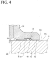
- the second insulator 65 is configured to face the wing inner surface 11b with the predetermined clearance C, with the first insulator 63 being tightly interposed between the outer peripheral planar part 62 and the wing inner surface 11b, in the above embodiment, this is not meant to be restrictive. That is, as shown in FIG. 6 , the second insulator 65 may be interposed between the inner peripheral planar part 64 and the wing inner surface 11b, with the first insulator 63 being tightly interposed between the outer peripheral planar part 62 and the wing inner surface 11b.
- the second insulator 65 is formed of a material softer than the material of the first insulator 63 and, when a fastening force of the fastening member 50 acts, a force of the door body 30 and the wing inner surface 11b being pressed to each other is preferably exerted mainly by the first insulator 63.
- the configuration can be such that the fuel sealing member 61 is caused to function as the second insulator 65.
- the fuel sealing member 61 preferably includes a core 68 made of, for example, PEEK, or the like, having a sufficient strength that can sustain the fastening force of the fastener member 50 and a seal part 69 provided to the outer peripheral part of the core 68 and made of a rubber-based material or the like softer than the material of the core 68.
- the fuel sealing member 61 as the second insulator 65 is interposed between the inner peripheral planar part 64 and the wing inner surface 11b, and the core 68 prevents the door body 30 and the wing inner surface 11b from being electrically in direct contact with each other.
- the configuration may be such that the cross-sectional area, density, an others of the fuel sealing member 61 are set so that the door body 30 and the wing inner surface 11b are not electrically in direct contact with each other even when the first insulator 63 falls off and the fuel sealing member 61 is interposed between the inner peripheral planar part 64 and the wing inner surface 11b to be crushed inside the ring groove 60.
- door body 30 and the clamp ring 40 are described in the above embodiment, their fastening structure, the shapes of the door body 30 and the clamp ring 40, and others are not intended to be restricted to the above, and can be configured in another manner as appropriate.
- the materials of the first insulator 63 and the second insulator 65 are not restricted to the above-listed materials.
- any of materials including polyimide, PET, ethylene-based resin, and others can be used as long as it satisfies necessary conditions, such as insulation properties, heat resistance, oil resistance, and adhesiveness.
Landscapes
- Engineering & Computer Science (AREA)
- Mechanical Engineering (AREA)
- Aviation & Aerospace Engineering (AREA)
- Special Wing (AREA)
- Gasket Seals (AREA)
- Connection Of Plates (AREA)
- Insulators (AREA)
Claims (5)
- Schließelement (20) für eine Öffnung (12), die an einer Platte (11), die eine Außenfläche einer Flugzeugzelle eines Flugzeugs bildet, ausgebildet ist,
das Schließelement (20) umfasst:einen Schließelementkörper (30), der so eingerichtet ist, dass er an einer Seitenfläche der Platte (11) vorgesehen ist und eine Außenabmessung aufweist, die größer ist als eine Außenabmessung der Öffnung (12), um die Öffnung (12) zu schließen;ein ringförmiges Klemmelement (40), das so eingerichtet ist, dass es auf einer anderen Seitenfläche der Platte (11) vorgesehen ist und eine Außenabmessung aufweist, die größer ist als die Außenabmessung der Öffnung (12), und
ein Befestigungselement (50) zur gemeinsamen Befestigung des Schließelementkörpers (30) und des Klemmelements (40),
ein Außenumfangsteil (62) des Schließelementkörpers (30) und ein Außenumfangsteil des Klemmelements (40) dazu eingerichtet sind, an beiden Seitenflächen der Platte (11) zu liegen,
das Schließelement (20) einen ersten Abstandshalter (63) und ein zweiten Abstandshalter (65) umfasst, die eingerichtet sind, zwischen dem Außenumfangsteil (62) des Schließelementkörpers (30) und einer Stirnfläche (11b) der Platte (11) zu liegen, die dem Außenumfangsteil (62) um die Öffnung herum gegenüberliegt,
der erste Abstandshalter (63) zwischen dem Außenumfangsteil (62) des Schließelementkörpers (30) und der Stirnfläche (11b) eingeschoben ist, wenn die Öffnung (12) mit dem Schließelementkörper (30) geschlossen ist, und der zweite Abstandshalter (65) zwischen dem Außenumfangsteil (62) des Schließelementkörpers (30) und der Stirnfläche (11b) zumindest in einem Zustand eingeschoben ist, in dem der erste Abstandshalter (63) abgefallen ist, gekennzeichnet dadurch, dass
wenn der erste Abstandshalter (63) zwischen dem Außenumfangsteil (62) des Schließelementkörpers (30) und der Stirnfläche (11b) eingeschoben ist, der zweite Abstandshalter (65) einen Freiraum (C) zu der Stirnfläche (11b) aufweist. - Schließelement für eine Öffnung nach Anspruch 1, wobei ein Abschnitt des Schließelementkörpers (30), der dem ersten Abstandshalter (63) gegenüberliegt, in dem Außenumfangsteil (62) eingerichtet ist, einen Freiraum (C2) zwischen dem Abschnitt und der Stirnfläche (11b) der Platte (11) in einem Zustand aufzuweisen, in dem der erste Abstandshalter (63) abgefallen ist und der zweite Abstandshalter (65) zwischen dem Außenumfangsteil (62) des Schließelementkörpers (30) und der Stirnfläche (11b) eingeschoben ist.
- Schließelement (20) für eine Öffnung (12) nach einem der Ansprüche 1 oder 2, wobei der erste Abstandshalter (63) und der zweite Abstandshalter (65) aus unterschiedlichen Materialien gebildet sind.
- Schließelement für eine Öffnung nach einem der Ansprüche 1 bis 3, wobei mindestens einer von dem ersten Abstandshalter (63) und dem zweiten Abstandshalter (65) eine Ringform aufweist und sich in einer Umfangsrichtung des Schließelementkörpers (30) erstreckt.
- Schließelement (20) für eine Öffnung (12) nach einem der Ansprüche 1 bis 4, eingerichtet um die Öffnung (12), die auf einem Hauptflügel, der die Flugzeugzelle ausbildet, vorgesehen ist, schließt, und einen Einlass oder einen Auslass für einen Kraftstofftank, der in dem Hauptflügel aufgenommen ist, ausbildet.
Priority Applications (1)
| Application Number | Priority Date | Filing Date | Title |
|---|---|---|---|
| EP15180358.2A EP2962933B1 (de) | 2010-05-17 | 2011-05-11 | Schliesselement für eine öffnung |
Applications Claiming Priority (2)
| Application Number | Priority Date | Filing Date | Title |
|---|---|---|---|
| JP2010112782A JP5529624B2 (ja) | 2010-05-17 | 2010-05-17 | 開口部の閉塞部材 |
| PCT/JP2011/002607 WO2011145291A1 (ja) | 2010-05-17 | 2011-05-11 | 開口部の閉塞部材 |
Related Child Applications (2)
| Application Number | Title | Priority Date | Filing Date |
|---|---|---|---|
| EP15180358.2A Division-Into EP2962933B1 (de) | 2010-05-17 | 2011-05-11 | Schliesselement für eine öffnung |
| EP15180358.2A Division EP2962933B1 (de) | 2010-05-17 | 2011-05-11 | Schliesselement für eine öffnung |
Publications (3)
| Publication Number | Publication Date |
|---|---|
| EP2572977A1 EP2572977A1 (de) | 2013-03-27 |
| EP2572977A4 EP2572977A4 (de) | 2014-07-30 |
| EP2572977B1 true EP2572977B1 (de) | 2016-04-27 |
Family
ID=44991413
Family Applications (2)
| Application Number | Title | Priority Date | Filing Date |
|---|---|---|---|
| EP15180358.2A Not-in-force EP2962933B1 (de) | 2010-05-17 | 2011-05-11 | Schliesselement für eine öffnung |
| EP11783230.3A Not-in-force EP2572977B1 (de) | 2010-05-17 | 2011-05-11 | Element zum verstopfen einer öffnung |
Family Applications Before (1)
| Application Number | Title | Priority Date | Filing Date |
|---|---|---|---|
| EP15180358.2A Not-in-force EP2962933B1 (de) | 2010-05-17 | 2011-05-11 | Schliesselement für eine öffnung |
Country Status (6)
| Country | Link |
|---|---|
| US (1) | US8684216B2 (de) |
| EP (2) | EP2962933B1 (de) |
| JP (1) | JP5529624B2 (de) |
| BR (1) | BR112012015834B1 (de) |
| CA (1) | CA2781961C (de) |
| WO (1) | WO2011145291A1 (de) |
Families Citing this family (16)
| Publication number | Priority date | Publication date | Assignee | Title |
|---|---|---|---|---|
| US9476251B2 (en) | 2011-08-19 | 2016-10-25 | Aerovironment, Inc. | Water-tight compartment with removable hatch and two-sided gel seal for multiple conduit access |
| JP5875377B2 (ja) * | 2012-01-13 | 2016-03-02 | 三菱航空機株式会社 | 航空機の機体 |
| US9016631B2 (en) * | 2012-04-09 | 2015-04-28 | R4 Integration, Inc. | Multi-purpose hatch system |
| EP2842865B1 (de) * | 2013-08-28 | 2019-12-18 | Airbus Operations GmbH | Fensterscheibe für ein flugwerk und verfahren zur herstellung davon |
| JP6381191B2 (ja) | 2013-09-11 | 2018-08-29 | 三菱重工業株式会社 | 燃料タンク用ダム |
| US9517830B2 (en) * | 2014-03-18 | 2016-12-13 | The Boeing Company | Seal design for vehicle and structure application |
| US9718533B2 (en) * | 2014-07-01 | 2017-08-01 | Textron Innovations, Inc. | Fuel tank access door systems and methods |
| JP6382019B2 (ja) * | 2014-08-08 | 2018-08-29 | 三菱航空機株式会社 | 航空機 |
| JP6674740B2 (ja) * | 2015-02-10 | 2020-04-01 | 三菱航空機株式会社 | バーストディスク装置および航空機 |
| US10112695B2 (en) * | 2015-08-20 | 2018-10-30 | Georgian Aerospace Llc | Receptacle, payload assembly and related methods for an aircraft |
| FR3043063B1 (fr) * | 2015-10-28 | 2017-11-24 | Aviacomp | Porte d'acces au reservoir de carburant ou a une zone seche d'un aeronef |
| FR3043062B1 (fr) * | 2015-10-28 | 2017-11-24 | Aviacomp | Porte d'acces au reservoir de carburant ou a une zone seche d'un aeronef |
| US10183735B2 (en) | 2016-02-01 | 2019-01-22 | The Boeing Company | Window frame assembly for aircraft |
| US11352063B2 (en) * | 2018-08-30 | 2022-06-07 | Clark Equipment Company | Frame access aperture |
| US11794124B2 (en) * | 2018-10-02 | 2023-10-24 | Snap Ships LLC | Connection systems for toy construction pieces, toy construction pieces including the same, and toy construction kits including the same |
| GB2600409B (en) * | 2020-10-27 | 2022-11-02 | Airbus Operations Ltd | Fuel tank assemblies |
Family Cites Families (15)
| Publication number | Priority date | Publication date | Assignee | Title |
|---|---|---|---|---|
| US4345739A (en) * | 1980-08-07 | 1982-08-24 | Barton Valve Company | Flanged sealing ring |
| US4428867A (en) * | 1981-11-02 | 1984-01-31 | Lockheed Corporation | Electrically conductive structural adhesive |
| US4579248A (en) * | 1983-11-10 | 1986-04-01 | The Boeing Company | Access panel assembly for aircraft fuel tank |
| US4530443A (en) * | 1983-11-10 | 1985-07-23 | The Boeing Company | Unitary access panel for aircraft fuel tanks |
| JPS60131395A (ja) | 1983-12-19 | 1985-07-13 | Tech Res & Dev Inst Of Japan Def Agency | 掃海索展開装置 |
| US4597583A (en) * | 1985-07-08 | 1986-07-01 | Felt Products Mfg. Co. | Gasket assembly for sealing covers to automotive engines |
| JPH0533600Y2 (de) * | 1985-08-30 | 1993-08-26 | ||
| JP2001004031A (ja) * | 1999-04-21 | 2001-01-09 | Bridgestone Corp | ガスケット及びその製造方法 |
| CA2508734C (en) * | 2002-12-06 | 2008-09-23 | Yachiyo Industry Co., Ltd. | Cover-mounting structure of plastic container |
| ATE500526T1 (de) | 2005-12-13 | 2011-03-15 | Varioptic Sa | Hermetische elektrowettingvorrichtung |
| US7576966B2 (en) * | 2006-02-23 | 2009-08-18 | The Boeing Company | Method and system for electrical bonding of fuel tank penetrations |
| US8091831B2 (en) * | 2006-11-28 | 2012-01-10 | Airbus Deutschland Gmbh | Aircraft with door seal arrangement |
| ES2347507B1 (es) * | 2007-12-27 | 2011-08-17 | Airbus Operations, S.L. | Boca de acceso de aeronave optimizada. |
| US8443575B1 (en) * | 2009-10-27 | 2013-05-21 | The Boeing Company | Composite access door |
| ES2404456B1 (es) * | 2011-01-26 | 2014-04-29 | Airbus Operations S.L. | Montaje de una boca de acceso en el revestimiento inferior de un ala de aeronave realizada con un material compuesto. |
-
2010
- 2010-05-17 JP JP2010112782A patent/JP5529624B2/ja not_active Expired - Fee Related
-
2011
- 2011-05-11 US US13/511,496 patent/US8684216B2/en active Active
- 2011-05-11 EP EP15180358.2A patent/EP2962933B1/de not_active Not-in-force
- 2011-05-11 BR BR112012015834-1A patent/BR112012015834B1/pt not_active IP Right Cessation
- 2011-05-11 WO PCT/JP2011/002607 patent/WO2011145291A1/ja not_active Ceased
- 2011-05-11 EP EP11783230.3A patent/EP2572977B1/de not_active Not-in-force
- 2011-05-11 CA CA2781961A patent/CA2781961C/en active Active
Non-Patent Citations (1)
| Title |
|---|
| None * |
Also Published As
| Publication number | Publication date |
|---|---|
| JP2011240754A (ja) | 2011-12-01 |
| BR112012015834A2 (pt) | 2016-06-14 |
| US20130062352A1 (en) | 2013-03-14 |
| CA2781961C (en) | 2014-09-02 |
| US8684216B2 (en) | 2014-04-01 |
| BR112012015834B1 (pt) | 2020-07-07 |
| EP2962933A1 (de) | 2016-01-06 |
| WO2011145291A1 (ja) | 2011-11-24 |
| EP2572977A4 (de) | 2014-07-30 |
| EP2962933B1 (de) | 2016-12-07 |
| CA2781961A1 (en) | 2011-11-24 |
| JP5529624B2 (ja) | 2014-06-25 |
| EP2572977A1 (de) | 2013-03-27 |
Similar Documents
| Publication | Publication Date | Title |
|---|---|---|
| EP2962933B1 (de) | Schliesselement für eine öffnung | |
| US5014934A (en) | Removable seal for discontinuities in aircraft skin | |
| US8662451B2 (en) | Manhole assembly in the lower skin of an aircraft wing made of a composite material | |
| US6119305A (en) | Sealing elements | |
| CA2703575C (en) | Lightning protection aircraft skin assembly | |
| EP2441678B1 (de) | Blitzschlagschutz für Flugzeuge | |
| US5175665A (en) | Lighting resistant composite structures | |
| CA2827997C (en) | Insulated and sealed cap assembly for a fastener component | |
| EP4005931B1 (de) | Verankerungsmutter für ein eme-schutzkappensystem | |
| EP2500272A2 (de) | Kupplungsstruktur für Luftrahmenkomponenten | |
| EP3059172B1 (de) | Flugzeugstruktur, verfahren zur herstellung einer struktur für ein flugzeug und verfahren zur herstellung von entwurfsinformationen einer struktur für ein flugzeug | |
| JP7664704B2 (ja) | 一方の側からの雷害耐性の設置 | |
| EP3611098A2 (de) | Druckmontierte fensteranordnung | |
| WO2014126652A1 (en) | Wing fuel tank access door | |
| EP2535264A1 (de) | Verschlusselement zum öffnen | |
| EP2606544B1 (de) | Neue dichtungsvorrichtung | |
| US9309003B2 (en) | Access door for possible use with a helicopter fuel tank | |
| KR100417980B1 (ko) | 항공기의 내부 검사를 위한 홀 구조 | |
| AU2023274151A1 (en) | Horn Speaker Cover Assembly |
Legal Events
| Date | Code | Title | Description |
|---|---|---|---|
| PUAI | Public reference made under article 153(3) epc to a published international application that has entered the european phase |
Free format text: ORIGINAL CODE: 0009012 |
|
| 17P | Request for examination filed |
Effective date: 20120620 |
|
| AK | Designated contracting states |
Kind code of ref document: A1 Designated state(s): AL AT BE BG CH CY CZ DE DK EE ES FI FR GB GR HR HU IE IS IT LI LT LU LV MC MK MT NL NO PL PT RO RS SE SI SK SM TR |
|
| DAX | Request for extension of the european patent (deleted) | ||
| A4 | Supplementary search report drawn up and despatched |
Effective date: 20140627 |
|
| RIC1 | Information provided on ipc code assigned before grant |
Ipc: B64C 1/14 20060101AFI20140623BHEP Ipc: B64C 3/34 20060101ALI20140623BHEP |
|
| 17Q | First examination report despatched |
Effective date: 20150319 |
|
| GRAP | Despatch of communication of intention to grant a patent |
Free format text: ORIGINAL CODE: EPIDOSNIGR1 |
|
| INTG | Intention to grant announced |
Effective date: 20151022 |
|
| RAP1 | Party data changed (applicant data changed or rights of an application transferred) |
Owner name: MITSUBISHI AIRCRAFT CORPORATION |
|
| RIN1 | Information on inventor provided before grant (corrected) |
Inventor name: TACHIBANA, KAZUKI |
|
| GRAS | Grant fee paid |
Free format text: ORIGINAL CODE: EPIDOSNIGR3 |
|
| GRAR | Information related to intention to grant a patent recorded |
Free format text: ORIGINAL CODE: EPIDOSNIGR71 |
|
| GRAA | (expected) grant |
Free format text: ORIGINAL CODE: 0009210 |
|
| INTG | Intention to grant announced |
Effective date: 20160311 |
|
| AK | Designated contracting states |
Kind code of ref document: B1 Designated state(s): AL AT BE BG CH CY CZ DE DK EE ES FI FR GB GR HR HU IE IS IT LI LT LU LV MC MK MT NL NO PL PT RO RS SE SI SK SM TR |
|
| REG | Reference to a national code |
Ref country code: GB Ref legal event code: FG4D |
|
| REG | Reference to a national code |
Ref country code: CH Ref legal event code: EP |
|
| REG | Reference to a national code |
Ref country code: AT Ref legal event code: REF Ref document number: 794455 Country of ref document: AT Kind code of ref document: T Effective date: 20160515 |
|
| REG | Reference to a national code |
Ref country code: IE Ref legal event code: FG4D |
|
| REG | Reference to a national code |
Ref country code: FR Ref legal event code: PLFP Year of fee payment: 6 |
|
| REG | Reference to a national code |
Ref country code: DE Ref legal event code: R096 Ref document number: 602011025979 Country of ref document: DE |
|
| REG | Reference to a national code |
Ref country code: LT Ref legal event code: MG4D |
|
| PG25 | Lapsed in a contracting state [announced via postgrant information from national office to epo] |
Ref country code: BE Free format text: LAPSE BECAUSE OF NON-PAYMENT OF DUE FEES Effective date: 20160531 |
|
| REG | Reference to a national code |
Ref country code: NL Ref legal event code: MP Effective date: 20160427 |
|
| REG | Reference to a national code |
Ref country code: AT Ref legal event code: MK05 Ref document number: 794455 Country of ref document: AT Kind code of ref document: T Effective date: 20160427 |
|
| PG25 | Lapsed in a contracting state [announced via postgrant information from national office to epo] |
Ref country code: NL Free format text: LAPSE BECAUSE OF FAILURE TO SUBMIT A TRANSLATION OF THE DESCRIPTION OR TO PAY THE FEE WITHIN THE PRESCRIBED TIME-LIMIT Effective date: 20160427 |
|
| PG25 | Lapsed in a contracting state [announced via postgrant information from national office to epo] |
Ref country code: PL Free format text: LAPSE BECAUSE OF FAILURE TO SUBMIT A TRANSLATION OF THE DESCRIPTION OR TO PAY THE FEE WITHIN THE PRESCRIBED TIME-LIMIT Effective date: 20160427 Ref country code: FI Free format text: LAPSE BECAUSE OF FAILURE TO SUBMIT A TRANSLATION OF THE DESCRIPTION OR TO PAY THE FEE WITHIN THE PRESCRIBED TIME-LIMIT Effective date: 20160427 Ref country code: NO Free format text: LAPSE BECAUSE OF FAILURE TO SUBMIT A TRANSLATION OF THE DESCRIPTION OR TO PAY THE FEE WITHIN THE PRESCRIBED TIME-LIMIT Effective date: 20160727 Ref country code: LT Free format text: LAPSE BECAUSE OF FAILURE TO SUBMIT A TRANSLATION OF THE DESCRIPTION OR TO PAY THE FEE WITHIN THE PRESCRIBED TIME-LIMIT Effective date: 20160427 |
|
| PG25 | Lapsed in a contracting state [announced via postgrant information from national office to epo] |
Ref country code: HR Free format text: LAPSE BECAUSE OF FAILURE TO SUBMIT A TRANSLATION OF THE DESCRIPTION OR TO PAY THE FEE WITHIN THE PRESCRIBED TIME-LIMIT Effective date: 20160427 Ref country code: PT Free format text: LAPSE BECAUSE OF FAILURE TO SUBMIT A TRANSLATION OF THE DESCRIPTION OR TO PAY THE FEE WITHIN THE PRESCRIBED TIME-LIMIT Effective date: 20160829 Ref country code: SE Free format text: LAPSE BECAUSE OF FAILURE TO SUBMIT A TRANSLATION OF THE DESCRIPTION OR TO PAY THE FEE WITHIN THE PRESCRIBED TIME-LIMIT Effective date: 20160427 Ref country code: AT Free format text: LAPSE BECAUSE OF FAILURE TO SUBMIT A TRANSLATION OF THE DESCRIPTION OR TO PAY THE FEE WITHIN THE PRESCRIBED TIME-LIMIT Effective date: 20160427 Ref country code: ES Free format text: LAPSE BECAUSE OF FAILURE TO SUBMIT A TRANSLATION OF THE DESCRIPTION OR TO PAY THE FEE WITHIN THE PRESCRIBED TIME-LIMIT Effective date: 20160427 Ref country code: GR Free format text: LAPSE BECAUSE OF FAILURE TO SUBMIT A TRANSLATION OF THE DESCRIPTION OR TO PAY THE FEE WITHIN THE PRESCRIBED TIME-LIMIT Effective date: 20160728 Ref country code: LV Free format text: LAPSE BECAUSE OF FAILURE TO SUBMIT A TRANSLATION OF THE DESCRIPTION OR TO PAY THE FEE WITHIN THE PRESCRIBED TIME-LIMIT Effective date: 20160427 Ref country code: RS Free format text: LAPSE BECAUSE OF FAILURE TO SUBMIT A TRANSLATION OF THE DESCRIPTION OR TO PAY THE FEE WITHIN THE PRESCRIBED TIME-LIMIT Effective date: 20160427 |
|
| PG25 | Lapsed in a contracting state [announced via postgrant information from national office to epo] |
Ref country code: IT Free format text: LAPSE BECAUSE OF FAILURE TO SUBMIT A TRANSLATION OF THE DESCRIPTION OR TO PAY THE FEE WITHIN THE PRESCRIBED TIME-LIMIT Effective date: 20160427 Ref country code: BE Free format text: LAPSE BECAUSE OF FAILURE TO SUBMIT A TRANSLATION OF THE DESCRIPTION OR TO PAY THE FEE WITHIN THE PRESCRIBED TIME-LIMIT Effective date: 20160427 |
|
| REG | Reference to a national code |
Ref country code: CH Ref legal event code: PL |
|
| REG | Reference to a national code |
Ref country code: DE Ref legal event code: R097 Ref document number: 602011025979 Country of ref document: DE |
|
| PG25 | Lapsed in a contracting state [announced via postgrant information from national office to epo] |
Ref country code: MC Free format text: LAPSE BECAUSE OF FAILURE TO SUBMIT A TRANSLATION OF THE DESCRIPTION OR TO PAY THE FEE WITHIN THE PRESCRIBED TIME-LIMIT Effective date: 20160427 Ref country code: CZ Free format text: LAPSE BECAUSE OF FAILURE TO SUBMIT A TRANSLATION OF THE DESCRIPTION OR TO PAY THE FEE WITHIN THE PRESCRIBED TIME-LIMIT Effective date: 20160427 Ref country code: RO Free format text: LAPSE BECAUSE OF FAILURE TO SUBMIT A TRANSLATION OF THE DESCRIPTION OR TO PAY THE FEE WITHIN THE PRESCRIBED TIME-LIMIT Effective date: 20160427 Ref country code: SK Free format text: LAPSE BECAUSE OF FAILURE TO SUBMIT A TRANSLATION OF THE DESCRIPTION OR TO PAY THE FEE WITHIN THE PRESCRIBED TIME-LIMIT Effective date: 20160427 Ref country code: LI Free format text: LAPSE BECAUSE OF NON-PAYMENT OF DUE FEES Effective date: 20160531 Ref country code: DK Free format text: LAPSE BECAUSE OF FAILURE TO SUBMIT A TRANSLATION OF THE DESCRIPTION OR TO PAY THE FEE WITHIN THE PRESCRIBED TIME-LIMIT Effective date: 20160427 Ref country code: EE Free format text: LAPSE BECAUSE OF FAILURE TO SUBMIT A TRANSLATION OF THE DESCRIPTION OR TO PAY THE FEE WITHIN THE PRESCRIBED TIME-LIMIT Effective date: 20160427 Ref country code: CH Free format text: LAPSE BECAUSE OF NON-PAYMENT OF DUE FEES Effective date: 20160531 |
|
| REG | Reference to a national code |
Ref country code: IE Ref legal event code: MM4A |
|
| PG25 | Lapsed in a contracting state [announced via postgrant information from national office to epo] |
Ref country code: SM Free format text: LAPSE BECAUSE OF FAILURE TO SUBMIT A TRANSLATION OF THE DESCRIPTION OR TO PAY THE FEE WITHIN THE PRESCRIBED TIME-LIMIT Effective date: 20160427 |
|
| PLBE | No opposition filed within time limit |
Free format text: ORIGINAL CODE: 0009261 |
|
| STAA | Information on the status of an ep patent application or granted ep patent |
Free format text: STATUS: NO OPPOSITION FILED WITHIN TIME LIMIT |
|
| 26N | No opposition filed |
Effective date: 20170130 |
|
| REG | Reference to a national code |
Ref country code: FR Ref legal event code: PLFP Year of fee payment: 7 |
|
| PG25 | Lapsed in a contracting state [announced via postgrant information from national office to epo] |
Ref country code: SI Free format text: LAPSE BECAUSE OF FAILURE TO SUBMIT A TRANSLATION OF THE DESCRIPTION OR TO PAY THE FEE WITHIN THE PRESCRIBED TIME-LIMIT Effective date: 20160427 Ref country code: IE Free format text: LAPSE BECAUSE OF NON-PAYMENT OF DUE FEES Effective date: 20160511 |
|
| REG | Reference to a national code |
Ref country code: FR Ref legal event code: PLFP Year of fee payment: 8 |
|
| PG25 | Lapsed in a contracting state [announced via postgrant information from national office to epo] |
Ref country code: CY Free format text: LAPSE BECAUSE OF FAILURE TO SUBMIT A TRANSLATION OF THE DESCRIPTION OR TO PAY THE FEE WITHIN THE PRESCRIBED TIME-LIMIT Effective date: 20160427 Ref country code: HU Free format text: LAPSE BECAUSE OF FAILURE TO SUBMIT A TRANSLATION OF THE DESCRIPTION OR TO PAY THE FEE WITHIN THE PRESCRIBED TIME-LIMIT; INVALID AB INITIO Effective date: 20110511 |
|
| PG25 | Lapsed in a contracting state [announced via postgrant information from national office to epo] |
Ref country code: MK Free format text: LAPSE BECAUSE OF FAILURE TO SUBMIT A TRANSLATION OF THE DESCRIPTION OR TO PAY THE FEE WITHIN THE PRESCRIBED TIME-LIMIT Effective date: 20160427 Ref country code: TR Free format text: LAPSE BECAUSE OF FAILURE TO SUBMIT A TRANSLATION OF THE DESCRIPTION OR TO PAY THE FEE WITHIN THE PRESCRIBED TIME-LIMIT Effective date: 20160427 Ref country code: IS Free format text: LAPSE BECAUSE OF FAILURE TO SUBMIT A TRANSLATION OF THE DESCRIPTION OR TO PAY THE FEE WITHIN THE PRESCRIBED TIME-LIMIT Effective date: 20160427 Ref country code: LU Free format text: LAPSE BECAUSE OF NON-PAYMENT OF DUE FEES Effective date: 20160511 Ref country code: MT Free format text: LAPSE BECAUSE OF NON-PAYMENT OF DUE FEES Effective date: 20160531 |
|
| PG25 | Lapsed in a contracting state [announced via postgrant information from national office to epo] |
Ref country code: BG Free format text: LAPSE BECAUSE OF FAILURE TO SUBMIT A TRANSLATION OF THE DESCRIPTION OR TO PAY THE FEE WITHIN THE PRESCRIBED TIME-LIMIT Effective date: 20160427 |
|
| PG25 | Lapsed in a contracting state [announced via postgrant information from national office to epo] |
Ref country code: AL Free format text: LAPSE BECAUSE OF FAILURE TO SUBMIT A TRANSLATION OF THE DESCRIPTION OR TO PAY THE FEE WITHIN THE PRESCRIBED TIME-LIMIT Effective date: 20160427 |
|
| REG | Reference to a national code |
Ref country code: FR Ref legal event code: PLFP Year of fee payment: 13 |
|
| PGFP | Annual fee paid to national office [announced via postgrant information from national office to epo] |
Ref country code: GB Payment date: 20230330 Year of fee payment: 13 |
|
| PGFP | Annual fee paid to national office [announced via postgrant information from national office to epo] |
Ref country code: FR Payment date: 20230411 Year of fee payment: 13 Ref country code: DE Payment date: 20230331 Year of fee payment: 13 |
|
| REG | Reference to a national code |
Ref country code: DE Ref legal event code: R119 Ref document number: 602011025979 Country of ref document: DE |
|
| GBPC | Gb: european patent ceased through non-payment of renewal fee |
Effective date: 20240511 |
|
| PG25 | Lapsed in a contracting state [announced via postgrant information from national office to epo] |
Ref country code: DE Free format text: LAPSE BECAUSE OF NON-PAYMENT OF DUE FEES Effective date: 20241203 |
|
| PG25 | Lapsed in a contracting state [announced via postgrant information from national office to epo] |
Ref country code: FR Free format text: LAPSE BECAUSE OF NON-PAYMENT OF DUE FEES Effective date: 20240531 |
|
| PG25 | Lapsed in a contracting state [announced via postgrant information from national office to epo] |
Ref country code: GB Free format text: LAPSE BECAUSE OF NON-PAYMENT OF DUE FEES Effective date: 20240511 |