EP2572985B1 - Verfahren und System zum dualen Einstieg für ein Flugzeug - Google Patents
Verfahren und System zum dualen Einstieg für ein Flugzeug Download PDFInfo
- Publication number
- EP2572985B1 EP2572985B1 EP12183860.1A EP12183860A EP2572985B1 EP 2572985 B1 EP2572985 B1 EP 2572985B1 EP 12183860 A EP12183860 A EP 12183860A EP 2572985 B1 EP2572985 B1 EP 2572985B1
- Authority
- EP
- European Patent Office
- Prior art keywords
- aircraft
- passengers
- doorway
- width
- flow
- Prior art date
- Legal status (The legal status is an assumption and is not a legal conclusion. Google has not performed a legal analysis and makes no representation as to the accuracy of the status listed.)
- Active
Links
Images



Classifications
-
- B—PERFORMING OPERATIONS; TRANSPORTING
- B64—AIRCRAFT; AVIATION; COSMONAUTICS
- B64C—AEROPLANES; HELICOPTERS
- B64C1/00—Fuselages; Constructional features common to fuselages, wings, stabilising surfaces or the like
- B64C1/14—Windows; Doors; Hatch covers or access panels; Surrounding frame structures; Canopies; Windscreens accessories therefor, e.g. pressure sensors, water deflectors, hinges, seals, handles, latches, windscreen wipers
- B64C1/1407—Doors; surrounding frames
- B64C1/1423—Passenger doors
-
- B—PERFORMING OPERATIONS; TRANSPORTING
- B64—AIRCRAFT; AVIATION; COSMONAUTICS
- B64C—AEROPLANES; HELICOPTERS
- B64C1/00—Fuselages; Constructional features common to fuselages, wings, stabilising surfaces or the like
- B64C1/18—Floors
-
- B—PERFORMING OPERATIONS; TRANSPORTING
- B64—AIRCRAFT; AVIATION; COSMONAUTICS
- B64D—EQUIPMENT FOR FITTING IN OR TO AIRCRAFT; FLIGHT SUITS; PARACHUTES; ARRANGEMENT OR MOUNTING OF POWER PLANTS OR PROPULSION TRANSMISSIONS IN AIRCRAFT
- B64D11/00—Passenger or crew accommodation; Flight-deck installations not otherwise provided for
-
- B—PERFORMING OPERATIONS; TRANSPORTING
- B64—AIRCRAFT; AVIATION; COSMONAUTICS
- B64F—GROUND OR AIRCRAFT-CARRIER-DECK INSTALLATIONS SPECIALLY ADAPTED FOR USE IN CONNECTION WITH AIRCRAFT; DESIGNING, MANUFACTURING, ASSEMBLING, CLEANING, MAINTAINING OR REPAIRING AIRCRAFT, NOT OTHERWISE PROVIDED FOR; HANDLING, TRANSPORTING, TESTING OR INSPECTING AIRCRAFT COMPONENTS, NOT OTHERWISE PROVIDED FOR
- B64F1/00—Ground or aircraft-carrier-deck installations
- B64F1/30—Ground or aircraft-carrier-deck installations for embarking or disembarking passengers
Definitions
- the present disclosure relates generally to aircraft and, in particular, to passenger flow control systems for aircraft. Still more particularly, the present disclosure relates to a method and apparatus for boarding passengers onto and deplaning passengers from an aircraft.
- This passenger cabin may be a section of the aircraft with seats in which passengers travel.
- a passenger cabin may be divided into several parts.
- Seats within the passenger area may be arranged in different groupings. These groupings may be defined by seats arranged in rows. One or more aisles also may be present in the aircraft to further divide the seats into the groupings. Further, different passenger areas for different classes of travel may be present for different groupings of seats. The amount of space provided per passenger may increase with the presence of a higher class of travel, such as first class or business class as compared to economy class.
- Configurations of seats may be made with a goal of increasing the density of passengers in a cabin. As the number of passengers that can be seated increases, time for boarding and/or disembarking of passengers from an aircraft may be a factor taken into account when operating the aircraft.
- the time needed for passengers to board and/or disembark an aircraft may be greater than desired. Reducing the amount of time needed to load and/or unload passengers may be desirable. By reducing the amount of time needed to load and/or unload passengers, the amount of time needed between flights may be decreased. As a result of reduced time between flights, an aircraft also may fly more flights during a day through the reduction of time at the gate.
- the effect of reduced gate time on increasing availability of aircraft for additional flights may increase as the size of the aircraft decreases. Typically, smaller aircraft may be used for shorter flights and perform more flights during a day than larger aircraft. Some factors involved in reducing the amount of time at the gate may be the amount of fuel and cargo that are loaded and unloaded.
- the corridor connects the doorway to a first aisle and a second aisle in the interior of the aircraft.
- the flow of the passengers is at least one of a dual staggered flow and a dual flow of the passengers.
- the aircraft has at least one aisle in the interior of the aircraft.
- the different advantageous embodiments recognize and take into account one or more different considerations.
- the different advantageous embodiments recognize and take into account that with boarding aircraft, the configuration of the aircraft may affect the time needed for passengers to reach their seats on an aircraft. For example, as the length of an aisle in the aircraft increases, backups in passengers along the aisle may occur more frequently.
- the different advantageous embodiments recognize and take into account that passengers may stop to place carry-on luggage in overhead bins.
- one manner in which loading may be made more efficient is to perform loading in groups based on locations in the aircraft or the design of the aircraft itself. For example, passengers with seat assignments near the rear of the aircraft may be allowed to board first with those having seats in the forward part of the aircraft boarding last. Additionally, aircraft with aft boarding stairs may be used for boarding simultaneously through two separate doors, one forward and one aft. This type of boarding may result in congestion between passengers meeting in aisles in locations between the doors. Even with this type of loading of passengers, backups still may occur in an aisle.
- the different advantageous embodiments also recognize and take into account that in some aircraft, more than one aisle may be present. For example, an aircraft may have two aisles that allow for passengers to reach their seats more quickly through those aisles as compared to a single aisle. The different advantageous embodiments recognize and take into account that although two aisles may provide for quicker boarding of passengers, entry into the aircraft to reach those aisles may still be a source of congestion.
- the different advantageous embodiments recognize and take into account that the time needed to board passengers into aircraft may be reduced by loading passengers using more than one door.
- a door closer to the front of the aircraft may be used to allow passengers to enter the aircraft down one aisle while a second door located farther to the aft portion of the aircraft may be used to allow passengers to enter and find seats using a second aisle in the aircraft.
- the different advantageous embodiments also recognize and take into account that if two aisles are used, boarding of passengers through a single door may occur from both aisles with the use of a larger doorway.
- the different advantageous embodiments recognize and take into account that the width of the door, as well as the width of the doorway, may be increased to allow substantially two passengers to enter the aircraft at substantially the same time.
- This type of boarding may be considered dual boarding or dual staggered boarding of passengers. With staggered dual boarding, some passengers may enter side-by-side while other passengers may enter in a more staggered fashion into the aircraft through the doorway.
- the corridor leading to the aisles also may have a width to allow for passengers to walk substantially side-by-side or in a staggered fashion in some cases.
- the different advantageous embodiments recognize and take into account that currently available aircraft doorways for passengers may be unable to accommodate dual entry by passengers.
- dual entry may occur when two passengers are able to walk side-by-side through a doorway in the aircraft.
- the different advantageous embodiments recognize and take into account that most designers designing aircraft and loading systems for aircraft may not have taken into account federal aviation requirements regarding the space inside the doorway in a correct manner.
- the different advantageous embodiments recognize and take into account that space inside the doorway prior to reaching the aisles may be reserved for use by crew members.
- This space may be defined by federal aviation requirements set out by the Federal Aviation Administration.
- the different advantageous embodiments recognize and take into account that this space inside the doorway may not be used by passengers during some emergency situations.
- the different advantageous embodiments recognize and take into account, however, that the space inside the doorway may be used by passengers during normal boarding and does not need to be reserved for crew members during this process.
- the different advantageous embodiments recognize and take into account that this space inside the doorway may be used during normal boarding.
- the different advantageous embodiments recognize and take into account that the use of wider doorways for dual entry may not have been used because of a failure to take into account that the spaces reserved for emergency situations may be used during normal boarding.
- the different advantageous embodiments recognize and take into account that designers may not desire to move walls in a corridor to provide additional space in addition to the reserved spaces for use by passengers boarding the aircraft.
- the different advantageous embodiments recognize and take into account that increasing the widths of corridors may result in reducing the number of seats that can be placed in an aircraft.
- the different advantageous embodiments provide a method and apparatus for controlling the flow of passengers through a doorway into an aircraft in which the passengers may be arranged in two lines outside of the doorway in which the doorway is configured to allow at least a dual staggered entry of passengers through the doorway. These two lines may be next to each other outside of the door way.
- the flow of passengers may be controlled through a corridor connecting the doorway to a first aisle and a second aisle in the interior of the aircraft.
- the flow of the passengers may pass through a number of spaces in the corridor in which the number of spaces may be reserved for a number of crew members during an emergency operation in which passengers exit the aircraft.
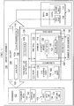
- aircraft environment 100 may be an environment in which passengers 102 may enter and exit aircraft 104 .
- aircraft 104 may have seats 106 .
- Aisles 107 may be present and may provide access to seats 106 .
- aisles 107 may comprise first aisle 108 and second aisle 110 .
- First aisle 108 and second aisle 110 may extend longitudinally through aircraft 104 between seats 106 .
- Aircraft 104 may have door 111 with doorway 112 .
- Passengers 102 may reach seats 106 by entering aircraft 104 through doorway 112 in aircraft 104 when door 111 is open.
- First aisle 108 and second aisle 110 may be reached from doorway 112 through corridor 114 .
- Corridor 114 may be in part defined by first wall 116 and second wall 118 . In these illustrative examples, these walls may take the form of bulkheads for aircraft 104 .
- Number of spaces 120 may be present.
- Number of spaces 120 may be spaces reserved for use during emergency operations. In other words, number of spaces 120 may be required to be clear for use by number of crew members 122 during an emergency exit from aircraft 104 .
- Number of spaces 120 may be defined by a regulatory agency and/or other organizations. For example, the regulatory agency may be the Federal Aviation Administration.
- number of spaces 120 may comprise first space 124 and second space 126 .
- First space 124 may be located by first wall 116 and second space 126 may be located by second wall 118 .
- passenger flow control system 128 may be implemented to load passengers 102 onto aircraft 104 .
- passenger flow control system 128 may be configuration 129 of at least one of doorway 112 and corridor 114 .
- the phrase "at least one of”, when used with a list of items, means different combinations of one or more of the listed items may be used and only one of each item in the list may be needed.
- “at least one of item A, item B, and item C” may include, for example, without limitation, item A, or item A and item B. This example also may include item A, item B, and item C, or item B and item C.
- Passenger flow control system 128 may operate to control flow 130 of passengers 102 onto aircraft 104 .
- Flow 130 of passengers 102 may be controlled to move passengers through doorway 112 into corridor 114 and then through first aisle 108 and second aisle 110 to reach seats 106 in these illustrative examples.
- corridor 114 may be a cross-aisle leading to first aisle 108 and second aisle 110 .
- passengers 102 may be arranged in lines 132 outside of aircraft 104 .
- passengers 102 may be arranged in two lines, first line 133 and second line 134 .
- Flow 130 of passengers 102 in first line 133 and second line 134 onto aircraft 104 may be controlled using at least one of doorway 112 and corridor 114 .
- a partition between first line 133 and second line 134 may be absent.
- corridor 114 may have first width 136 and doorway 112 may have second width 138 .
- First width 136 and second width 138 may be substantially the same in these illustrative examples.
- doorway 112 may be configured to allow at least dual staggered entry 140 of passengers 102 . Depending on passenger sizes 142 and/or carry-on items 144 for passengers 102, doorway 112 may allow for dual entry 146 of passengers 102 .
- flow 130 of passengers 102 also may be controlled through corridor 114 by passenger flow control system 128.
- the control of flow 130 of passengers 102 through corridor 114 may be such that flow 130 of passengers 102 passes through number of spaces 120 in corridor 114.
- number of spaces 120 may be located in corridor 114 between first wall 116 and second wall 118.
- first width 136 being substantially equal to second width 138, flow 130 of passengers 102 may pass through number of spaces 120. In this manner, flow 130 of passengers 102 may pass through doorway 112 and corridor 114 with reduced congestion or bottlenecks.
- flow 130 of passengers 102 may be dual staggered flow 148, dual flow 150, or a combination of the two. Dual flow 150 may be present depending on passenger sizes 142 and/or carry-on items 144.
- Dual flow 150 may be present when passengers 102 pass through at least one of doorway 112 and corridor 114 side-by-side. If passengers 102 are offset from each other rather than side-by-side, flow 130 may be dual staggered flow 148. In other words, when passenger sizes 142 are large enough for passengers 102 and/or carry-on items 144 are large enough, dual flow 150 may be present instead of dual staggered flow 148.
- first width 136 and/or second width 138 may be a usable width for these components.
- the actual width of doorway 112 may be larger than second width 138.
- This difference may take into account components for door 111 that may partially block doorway 112.
- a hinge for door 111 may partially block space in doorway 112 when door 111 is in an open position.
- second width 138 may be designed to be substantially equal to first width 136 by taking into account these factors.
- doorway 112 configured for dual staggered entry 140, dual entry 146, or both
- passengers 102 may enter aircraft 104 through doorway 112 more quickly as compared to currently used doors that may not allow for this type of entry.
- corridor 114 being configured to control flow 130 of passengers 102 to pass through number of spaces 120 in corridor 114, congestion of passengers 102 traveling to seats 106 may be reduced.
- flow 130 of passengers 102 through corridor 114 to first aisle 108 and second aisle 110 may occur more quickly.
- passenger flow control system 1208 the amount of time that aircraft 104 spends at a gate may be reduced. The reduction of this time may allow for increased number of flights.
- Passenger flow control system 128 may be especially useful when aircraft 104 is used to perform shorter flights. For example, passenger flow control system 128 may be especially useful on a short- to medium-range aircraft.
- a short flight may be one that is from about one hour to about two hours long.
- Airlines that operate aircraft using shorter flights may benefit greatly from using passenger flow control system 128. For example, if the time between flights at a gate is reduced by about 10 minutes, about six flights may result in a savings of about 60 minutes. This reduction in time may leave sufficient time for an additional flight in the same day. The additional flight may provide additional desired revenues for the same aircraft.
- passenger flow control system 128 also may be used to control the flow of passengers 102 from seats 106 out of aircraft 104.
- aircraft 104 may have more than one level in which seats are located. These additional seats may be seats in addition to seats 106. The flow of passengers may be controlled in a similar fashion or through other mechanisms depending on the particular implementation.
- another doorway may be present in which passengers may enter and reach first aisle 108 and second aisle 110.
- another door may be present to reach another set of aisles. This set of aisles may be for seats in a different class of seating as compared to seats 106.
- an advantageous embodiment may be used to manage flow 130 of passengers 102 in a manner that may reduce the amount of time needed to board passengers 102.
- the time that aircraft 104 may need to be at a gate may be reduced.
- an increased number of flights may be performed by the same aircraft.
- revenues generated by a particular aircraft also may be increased with the use of aircraft environment 100.
- Aircraft design environment 200 may be an example of a design environment that may be used to design different components for aircraft 104 shown in block form in Figure 1 .
- aircraft design environment 200 may be used for aircraft 104 and/or components such as passenger flow control system 128 in Figure 1 .
- design module 202 may be located in computer system 204.
- Design module 202 may be implemented using software, hardware, or a combination of the two.
- Computer system 204 may comprise a number of computers. When more than one computer is present in computer system 204, those computers may be in communication with each other using a medium, such as a network.
- design module 202 may generate passenger flow control system design 206 based on input 210.
- Passenger flow control system design 206 may be used to implement a passenger flow control system, such as passenger flow control system 128 in Figure 1 .
- Passenger flow control system design 206 may be generated by taking into account fuselage design 208 in these illustrative examples. In other illustrative examples, passenger flow control system design 206 may affect the design of fuselage design 208.
- input 210 may specify various goals and parameters.
- input 210 may include passenger density, number of passengers, aircraft size, desired time to seat passengers, desired time to deplane passengers, and other suitable types of input.
- design module 202 may generate configuration 212 for passenger flow control system design 206.
- Configuration 212 may include, for example, at least one of seat configuration 214, aisles 216, corridor 218, door 220, doorway 222, number of spaces 224, passenger entry process 226, and other suitable components for the aircraft.
- seat configuration 214 may be an arrangement of seats within an aircraft.
- Aisles 216 may identify the location of aisles relative to seats.
- Corridor 218 may be an identification of a space connecting the doorway to the aisles.
- Number of spaces 224 may be spaces reserved for use by crew members during emergency operations.
- Passenger entry process 226 may be the process for how passengers enter the aircraft.
- Corridor 218 may have first width 228 in these illustrative examples.
- Doorway 222 may have second width 230.
- first width 228 and second width 230 may be selected to be substantially equal to each other. Further, first width 228 and second width 230 may be selected to provide for dual staggered flow 232, dual flow 234, or a combination of the two in passenger entry process 226.
- first width 228 and second width 230 may be based on passenger sizes 236 and/or carry-on item sizes 238. For example, without limitation, values for these widths may be selected to allow passenger sizes 236 to pass through doorway 222 and/or corridor 218 with dual flow 234.
- Passenger sizes 236 include the passenger sizes that are within about a 97.5 th percentile for passenger sizes.
- passenger sizes 236 within about the 97.5 th percentile for passenger sizes may include the passengers sizes that are smaller than about the largest 2.5 percent of the passenger sizes. In particular, the largest 2.5 percent may be with respect to male passenger sizes.
- passenger sizes 236 may be with respect to height.
- two passengers having a height up to about the largest 2.5 percent of male heights may be allowed to pass through doorway 222 and corridor 218 side-by-side in dual flow 234.
- passenger sizes larger than the 97.5 th percentile passengers may pass through doorway 222 and corridor 218 using dual staggered flow 232.
- first width 228 for corridor 218 and second width 230 for doorway 222 may be selected based on allowing for dual flow 234 when a selected size for carry-on items in carry-on item sizes 238 is present.
- passenger flow control system design 206 may be generated for new aircraft, for reconfiguring current aircraft, and for other suitable purposes.
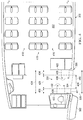
- Aircraft environment 300 in Figure 3 may be an example of a physical implementation for aircraft environment 100 shown in block form in Figure 1 .
- Aircraft environment 300 may include aircraft 302 located at gate 304.
- passengers 301 may board aircraft 302 from gate 304 through walkway 306.
- Walkway 306 may be a structure configured to provide passengers access to aircraft 302 from gate 304 in a manner that may protect passengers from the environment.
- Walkway 306 may be, for example, without limitation, a jet bridge, a passenger walkway, a passenger boarding bridge, a loading bridge, a passenger stairway, a passenger ramp, and other suitable platforms.
- aircraft 302 may have doors 308, 310, 312, 314, 316, 318, 320, and 322.
- Walkway 306 may be positioned relative to door 322 in this illustrative example.
- Passengers 301 may enter aircraft 302 by moving through walkway 306 and into aircraft 302 through doorway 324 for door 322. In these illustrative examples, entering aircraft 302 may be referred to as "boarding" aircraft 302.
- passengers 301 may leave aircraft 302 by moving from interior 332 through corridor 330 and out into walkway 306 through doorway 324. Leaving aircraft 302 may be referred to as "disembarking" aircraft 302 in the depicted examples.
- passenger flow control system 326 may be implemented with aircraft 302 to decrease the amount of time needed for passengers 301 to board aircraft 302, disembark aircraft 302, or a combination of the two.
- passenger flow control system 326 may control flow 328 of passengers 301 that enter aircraft 302 through doorway 324 and through corridor 330 in interior 332 of aircraft 302.
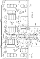
- FIG. 4 an illustration of a portion of an aircraft incorporating a passenger flow control system is depicted in accordance with an advantageous embodiment.
- a more detailed view of aircraft 302 with passenger flow control system 326 in Figure 3 is depicted in this partially exposed view.
- Passenger flow control system 326 may comprise doorway 324 and/or corridor 330.
- Doorway 324 may have width 408 or width 410.
- width 408 may be selected when dual staggered entry, dual entry, or some combination of the two is desired for entry into interior 332 of aircraft 302.
- width 408 may be about 60 inches while width 410 may be about 42 inches. These widths may be usable widths through which passengers may pass. As a result, the actual physical width of doorway 324 may be larger than width 408.
- Width 408 may be the width not blocked by components in doorway 324, such as hinge 411 for door 322. In other words, width 408 may be the usable width of doorway 324 for boarding passengers, deplaning passengers, or a combination of the two.
- corridor 330 may be located in interior 332 of aircraft 302. Corridor 330 may provide a connection between doorway 324, first aisle 416, and second aisle 418. First aisle 416 and second aisle 418 may provide access to seats 419.
- Corridor 330 may be defined in part by first wall 420 and second wall 422.
- corridor 330 may have width 424.
- width 424 of corridor 330 may be substantially equal to width 408. In this depicted example, width 424 may be about 60 inches.
- Width 424 in some cases, may be greater than width 408. However, increasing width 424 for corridor 330 to a value greater than width 408 for doorway 324 may result in an undesired loss of space in interior 332 of aircraft 302 that may not be used for other purposes. For example, a loss in number of seats 419 may occur if width 424 is increased to be greater in size than width 408.
- first space 426 may be located substantially adjacent to first wall 420 and second space 428 may be located substantially adjacent to second wall 422.
- first space 426 and second space 428 may be spaces reserved for use by crew members (not shown) during emergency exits. These spaces, however, may not be defined using physical structures. Instead, these spaces may be ones reserved for use by crew members (not shown) that also may not be used by passengers (not shown) during emergency exits of aircraft 302.
- first space 426 may have width 430 and depth 432.
- Second space 428 may have width 434 and depth 436.
- Width 430 and width 434 may each be about 12.25 inches.
- Depth 432 and depth 436 may each be about 20.5 inches.
- doorway 324 may have width 410.
- Width 410 may be substantially equal to width 429 within corridor 330.
- Width 429 may exclude width 430 for first space 426 and width 434 for second space 428. With width 410 for doorway 324 and width 429 for corridor 330, only single file entry and single file flow may occur.
- first space 426 and second space 428 may be used during entry of passengers (not shown) into aircraft 302
- width 408 may be selected for doorway 324 without changing width 424 of corridor 330.
- passenger flow control system 326 may move passengers (not shown) through first space 426 and second space 428 in these illustrative examples.
- width 424 of corridor 330 may be designed to have a smaller or smallest value possible to allow for dual staggered entry, dual entry, or a combination of the two through doorway 324.
- width 424 of corridor 330 may not need to be widened to take into account first space 426 and/or second space 428.
- door 322 with doorway 324 may be selected to have width 408 rather than width 410 without changing width 429 of corridor 330. In this manner, time needed to board and/or deplane aircraft 302 may be reduced without a reduction in seats available for passengers on aircraft 302.
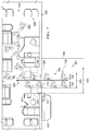
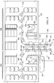
- passenger flow control system 501 also may be used at doorway 324 of aircraft 302.
- passenger flow control system 501 may comprise at least one of doorway 324 and corridor 506.
- Door 507 may be associated with doorway 324. Door 507 is shown in an open position. Doorway 324 may have width 508 rather than width 510. Doorway 324 may lead to corridor 506.
- corridor 506 may have width 512.
- Width 512 may be substantially equal to width 508.
- width 512 and width 508 may have a value of about 60 inches.
- Width 508 may be a usable width through which passengers may pass. As a result, the actual physical width of doorway 324 may be larger than width 508.
- Width 508 may be the width not blocked by components in doorway 324, such as hinge 511 for door 507. In other words, width 508 may be the usable width of doorway 324 for boarding passengers, deplaning passengers, or a combination of the two.
- Corridor 506 may be defined by first wall 514 and second wall 516. Corridor 506 may connect first aisle 518 and second aisle 520 to doorway 324 in these illustrative examples. First aisle 518 and second aisle 520 may be used to reach seats 522 within aircraft 302.
- first space 524 and second space 526 may be present.
- First space 524 may be adjacent to first wall 514.
- Second space 526 may be adjacent to second wall 516.
- First space 524 may have width 528 and depth 530.
- Second space 526 may have width 532 and depth 534. Width 528 and width 532 may each be about 12.25 inches.
- Depth 530 and depth 534 may each be about 20.5 inches.
- walkway 540 may be positioned relative to doorway 324. Walkway 540 may provide a path to gate 304 (not shown).
- FIG. 6 an illustration of a flow of passengers boarding an aircraft is depicted in accordance with an advantageous embodiment.
- flow 600 of passengers 602 is depicted.
- Flow 600 may begin with first line 604 and second line 606 on walkway 540.
- First line 604 and second line 606 may be next to each other.
- first line 604 and second line 606 may be considered to be parallel lines.
- first line 604 and second line 606 may enter aircraft 302 through doorway 324 as illustrated by flow 600 of passengers 602. Further, flow 600 may pass through corridor 506 to first aisle 518 and second aisle 520. In this manner, passengers 602 may reach seats 522.
- flow 600 of passengers 602 may take the form of dual flow 608.
- passengers 602 may enter aircraft 302 through doorway 324 side-by-side. This entry through doorway 324 may be a dual entry for doorway 324.
- passengers 602 also may move through corridor 506 in a side-by-side fashion before reaching first aisle 518 and/or second aisle 520.
- passenger 610 and passenger 612 in passengers 602 may be shown as passing through doorway 324 in a side-by-side fashion.
- flow 600 of passengers 602 is into aircraft 302 in this depicted example.
- flow 600 of passengers 602 may be out of aircraft 302.
- passengers 602 may use dual flow 608 provided by first line 604 and second line 606 to exit aircraft 302.
- flow 600 of passengers 602 also may be such that some of passengers 602 enter aircraft 302 while other passengers 602 exit aircraft 302.
- first line 604 of passengers 602 may be located at doorway 324 and enter aircraft 302 as shown by first flow 620 to reach first aisle 518 and second aisle 520 in first section 622 in aircraft 302.
- the movement of these other passengers in second flow 624 from first aisle 518 and second aisle 520 in second section 626 of aircraft 302 may form second line 606 as those passengers exit aircraft 302.
- first section 622 and second section 626 are relative to corridor 506. In other words, these sections are on either side of corridor 506. Also, these flows may pass through first space 524 and second space 526 in corridor 506.
- the sections may be identified differently in other illustrative examples.
- the sections may be selected as ones to facilitate boarding and exiting processes that may be used or desired for aircraft 302.
- FIG. 7 an illustration of a flow of passengers boarding an aircraft is depicted in accordance with an advantageous embodiment.
- flow 700 of passengers 702 is shown in dual staggered flow 704.
- passengers 702 may line up in first line 706 and second line 708. Thereafter, passengers 702 may move in flow 700 through doorway 324 and corridor 506 to first aisle 518 and second aisle 520.
- Dual staggered flow 704 passengers 702 may not pass through doorway 324 and/or corridor 506 in a side-by-side fashion. Instead, passengers 702 may be offset from each other. Dual staggered flow 704 through doorway 324 may result in staggered entry through doorway 324 in these illustrative examples. For example, passenger 710 and passenger 712 may pass through doorway 324 in a staggered fashion. Dual staggered flow 704 may be in contrast to a single file flow (not shown) in which passengers 702 may not have sufficient space to be offset from each other.
- Flow 700 of passengers 702 is into aircraft 302 in this depicted example.
- flow 700 of passengers 702 may be out of aircraft 302.
- passengers 702 may use dual staggered flow 704 provided by first line 706 and second line 708 to exit aircraft 302.
- dual flow 608 in Figure 6 and dual staggered flow 704 in Figure 7 are shown as independent flows with respect to each other, these flows may be combined in actual boarding of passengers 702.
- both dual flow 608 and dual staggered flow 704 may be present depending on the particular implementation.
- FIG. 8 an illustration of a passenger flow control system for an aircraft is depicted in accordance with an advantageous embodiment.
- flow 600 of passengers 602 from Figure 6 is depicted in a different configuration of aircraft 302.
- second aisle 520 from Figures 5 and 6 is excluded in aircraft 302.
- first aisle 518 may be used to reach seats 522 within aircraft 302.
- passengers 602 in first line 604 may enter first aisle 518 walking in a forward direction, while passengers 602 in second line 606 may enter first aisle 518 walking in an aft direction.
- passenger control system 501 may increase passenger flow and thereby reduce passenger boarding times even when only one aisle is present in aircraft 302.
- flow 600 of passengers 602 is into aircraft 302 in this depicted example.
- flow 600 of passengers 602 may be out of aircraft 302.
- passengers 602 may use dual flow 608 provided by first line 604 and second line 606 to exit aircraft 302.
- Passengers 602 coming from the forward portion of first aisle 518 may flow into first line 604 to exit aircraft 302, while passengers 602 coming from the aft portion of second aisle 520 may flow into second line 606 to exit aircraft 302.
- first line 604 of passenger 602 may be located at doorway 324 and enter aircraft 302 as shown by first flow 800 to reach first aisle 518 in first section 622 in aircraft 302.
- the movement of these other passengers in second flow 802 from first aisle 518 in second section 626 of aircraft 302 may form second line 606 as those passengers exit aircraft 302.
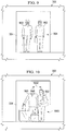
- FIG. 9 an illustration of a dual entry through a doorway is depicted in accordance with an advantageous embodiment.
- passenger 900 and passenger 902 may pass through doorway 324 by dual entry 904.
- passenger 900 and passenger 902 may pass through doorway 324 side-by-side.
- FIG. 10 an illustration of a dual staggered entry through a doorway is depicted in accordance with an advantageous embodiment.
- passenger 900 and passenger 902 may pass through doorway 324 using dual staggered entry 1000 in contrast to dual entry 904 in Figure 9 .
- passenger 900 and passenger 902 may have offset 1002 from each other when passing through doorway 324. Offset 1002 may be a distance from a single file entry in which passenger 900 is substantially behind passenger 902. Passenger 900 and passenger 902, however, may not enter using a single file entry in this example.
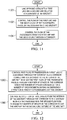
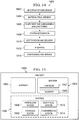
- FIG. 11 an illustration of a flowchart of a process for boarding an aircraft is depicted in accordance with an advantageous embodiment.
- the process illustrated in Figure 11 may be implemented using passenger flow control system 128 in Figure 1 .
- the process may begin by lining up passengers 102 into first line 133 and second line 134 relative to doorway 112 of aircraft 104 (operation 1100 ).
- First line 133 and second line 134 may be next to each other at doorway 112 in this illustrative example.
- the process then may control flow 130 of first line 133 and second line 134 of passengers 102 through doorway 112 into aircraft 104 (operation 1102 ).
- doorway 112 may be configured to allow at least one of dual staggered entry 140 and dual entry 146 of passengers 102 in first line 133 and second line 134 through doorway 112.
- the process may control flow 130 of passengers 102 from first line 133 and second line 134 through corridor 114 (operation 1104 ) with the process terminating thereafter.
- Corridor 114 may connect doorway 112 to first aisle 108 and second aisle 110 in aircraft 104.
- Flow 130 of passengers 102 in operation 1004 may pass through number of spaces 120 in corridor 114.
- Number of spaces 120 may be reserved for a number of crew members during emergency operations when passengers 102 exit aircraft 104.
- this process is illustrated for boarding aircraft 104, the process also may be used to disembark aircraft 104. Further, although the different processes are illustrated with respect to a walkway, these processes also may be used with other boarding platforms, such as a mobile stairway or other suitable platform.
- FIG. 12 an illustration of a flowchart of a process for managing movement of passengers is depicted in accordance with an illustrative embodiment.
- the process illustrated in Figure 12 may be implemented using passenger flow control system 128 in Figure 1 .
- the process may control first flow 620 of passengers 602 in first line 604 at doorway 324 through doorway 324 and corridor 506 connecting doorway 324 to the interior of the aircraft in which first flow 620 of passengers 602 passes through a number of spaces in corridor 506 which the number of spaces is reserved for a number of crew members during an emergency operation in which passengers 602 exit the aircraft (operation 1200 ).
- the process also may control second flow of passengers 602 from the interior of the aircraft through corridor 506 to doorway 324 in which passengers 602 in second flow 624 pass through the number of spaces in corridor 506 to exit aircraft 302 in second line 606 outside of the aircraft (operation 1202 ), with the process terminating thereafter.
- the first line may be adjacent to the second line outside of the aircraft.
- first flow 620 may be to first section 622 in aircraft 302, while second flow 624 may be from second section 626 in aircraft 302.
- each block in the flowcharts or block diagrams may represent a module, segment, function, and/or a portion of an operation or step.
- one or more of the blocks may be implemented as program code, in hardware, or a combination of the program code and hardware.
- the hardware may, for example, take the form of integrated circuits that are manufactured or configured to perform one or more operations in the flowcharts or block diagrams.
- the function or functions noted in the block may occur out of the order noted in the figures.
- two blocks shown in succession may be executed substantially concurrently, or the blocks may sometimes be performed in the reverse order, depending upon the functionality involved.
- other blocks may be added in addition to the illustrated blocks in a flowchart or block diagram.
- first line 133 and second line 134 may be formed based on locations of passengers 102 in an aircraft. For example, passengers farther back in a passenger cabin may be closer to the front of the line than passengers closer to the front of a passenger cabin. As another example, passengers of a higher class of travel, such as first class, may be closer to the front of the line than passengers of a lower class of travel, such as an economy class.
- the operation 1200 and operation 1202 in Figure 12 may occur at substantially the same time.
- the process in Figure 11 may be performed at one door in an aircraft while the process in Figure 12 may be used at another door of the aircraft.
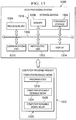
- Data processing system 1300 is an example of a data processing system that may be used to implement one or more computers in computer system 204 shown in block form in Figure 2 .
- data processing system 1300 includes communications framework 1302, which provides communications between processor unit 1304, memory 1306, persistent storage 1308, communications unit 1310, input/output (I/O) unit 1312, and display 1314.
- communications framework 1302 provides communications between processor unit 1304, memory 1306, persistent storage 1308, communications unit 1310, input/output (I/O) unit 1312, and display 1314.
- Processor unit 1304 serves to execute instructions for software that may be loaded into memory 1306.
- Processor unit 1304 may be a number of processors, a multi-processor core, or some other type of processor, depending on the particular implementation.
- a number, as used herein with reference to an item, means one or more items.
- processor unit 1304 may be implemented using a number of heterogeneous processor systems in which a main processor is present with secondary processors on a single chip.
- processor unit 1304 may be a symmetric multi-processor system containing multiple processors of the same type.
- Memory 1306 and persistent storage 1308 are examples of storage devices 1316.
- a storage device may be any piece of hardware that is capable of storing information, such as, for example, without limitation, data, program code in functional form, and other suitable information either on a temporary basis and/or a permanent basis.
- Storage devices 1316 also may be referred to as computer readable storage devices in these examples.
- Memory 1306, in these examples, may be, for example, a random access memory or any other suitable volatile or non-volatile storage device.
- Persistent storage 1308 may take various forms, depending on the particular implementation.
- persistent storage 1308 may contain one or more components or devices.
- persistent storage 1308 may be a hard drive, a flash memory, a rewritable optical disk, a rewritable magnetic tape, or some combination of the above.
- the media used by persistent storage 1308 also may be removable.
- a removable hard drive may be used for persistent storage 1308.
- Communications unit 1310 in these examples, provides for communications with other data processing systems or devices.
- communications unit 1310 may be a network interface card.
- Communications unit 1310 may provide communications through the use of either or both physical and wireless communications links.
- Input/output unit 1312 allows for input and output of data with other devices that may be connected to data processing system 1300.
- input/output unit 1312 may provide a connection for user input through a keyboard, a mouse, and/or some other suitable input device. Further, input/output unit 1312 may send output to a printer.
- Display 1314 provides a mechanism to display information to a user.
- Instructions for the operating system, applications, and/or programs may be located in storage devices 1316, which are in communication with processor unit 1304 through communications framework 1302.
- the instructions may be in a functional form on persistent storage 1308. These instructions may be loaded into memory 1306 for execution by processor unit 1304.
- the processes of the different embodiments may be performed by processor unit 1304 using computer implemented instructions, which may be located in a memory, such as memory 1306.
- program code may be referred to as program code, computer usable program code, or computer readable program code that may be read and executed by a processor in processor unit 1304.
- the program code in the different embodiments may be embodied on different physical or computer readable storage media, such as memory 1306 or persistent storage 1308.
- Program code 1318 may be located in a functional form on computer readable media 1320 that is selectively removable and may be loaded onto or transferred to data processing system 1300 for execution by processor unit 1304.
- Program code 1318 and computer readable media 1320 form computer program product 1322 in these examples.
- computer readable media 1320 may be computer readable storage media 1324 or computer readable signal media 1326.
- Computer readable storage media 1324 may include, for example, an optical or magnetic disk that may be inserted or placed into a drive or other device that is part of persistent storage 1308 for transfer onto a storage device, such as a hard drive, that is part of persistent storage 1308.
- Computer readable storage media 1324 also may take the form of a persistent storage, such as a hard drive, a thumb drive, or a flash memory, that may be connected to data processing system 1300. In some instances, computer readable storage media 1324 may not be removable from data processing system 1300. In these examples, computer readable storage media 1324 may be a physical or tangible storage device used to store program code 1318 rather than a medium that propagates or transmits program code 1318. Computer readable storage media 1324 also may be referred to as a computer readable tangible storage device or a computer readable physical storage device. In other words, computer readable storage media 1324 may be media that can be touched by a person.
- a persistent storage such as a hard drive, a thumb drive, or a flash memory
- program code 1318 may be transferred to data processing system 1300 using computer readable signal media 1326.
- Computer readable signal media 1326 may be, for example, a propagated data signal containing program code 1318.
- Computer readable signal media 1326 may be an electromagnetic signal, an optical signal, and/or any other suitable type of signal. These signals may be transmitted over communications links, such as wireless communications links, optical fiber cable, coaxial cable, a wire, and/or any other suitable type of communications link.
- the communications link and/or the connection may be physical or wireless in the illustrative examples.
- program code 1318 may be downloaded over a network to persistent storage 1308 from another device or data processing system through computer readable signal media 1326 for use within data processing system 1300.
- a program code stored in a computer readable storage medium in a server data processing system may be downloaded over a network from the server to data processing system 1300.
- the data processing system providing program code 1318 may be a server computer, a client computer, or some other device capable of storing and transmitting program code 1318.
- data processing system 1300 The different components illustrated for data processing system 1300 are not meant to provide architectural limitations to the manner in which different embodiments may be implemented.
- the different advantageous embodiments may be implemented in a data processing system including components in addition to and/or in place of those illustrated for data processing system 1300.
- Other components shown in Figure 13 can be varied from the illustrative examples shown.
- the different embodiments may be implemented using any hardware device or system capable of running a program code.
- processor unit 1304 may take the form of a hardware unit that has circuits that are manufactured or configured for a particular use. This type of hardware may perform operations without needing a program code to be loaded into a memory from a storage device to be configured to perform the operations.
- processor unit 1304 when processor unit 1304 takes the form of a hardware unit, processor unit 1304 may be a circuit system, an application specific integrated circuit (ASIC), a programmable logic device, or some other suitable type of hardware configured to perform a number of operations.
- ASIC application specific integrated circuit
- a programmable logic device the device may be configured to perform the number of operations. The device may be reconfigured at a later time or may be permanently configured to perform the number of operations.
- Examples of programmable logic devices include, for example, a programmable logic array, a programmable array logic, a field programmable logic array, a field programmable gate array, and other suitable hardware devices.
- program code 1318 may be omitted because the processes for the different embodiments are implemented in a hardware unit.
- processor unit 1304 may be implemented using a combination of processors found in computers and hardware units.
- Processor unit 1304 may have a number of hardware units and a number of processors that are configured to run program code 1318. With this depicted example, some of the processes may be implemented in the number of hardware units, while other processes may be implemented in the number of processors.
- a bus system may be used to implement communications framework 1302 and may be comprised of one or more buses, such as a system bus or an input/output bus.
- the bus system may be implemented using any suitable type of architecture that provides for a transfer of data between different components or devices attached to the bus system.
- a communications unit may include a number of more devices that transmit data, receive data, or transmit and receive data.
- a communications unit may be, for example, a modem or a network adapter, two network adapters, or some combination thereof.
- a memory may be, for example, memory 1306, or a cache, such as found in an interface and memory controller hub that may be present in communications framework 1302.
- aircraft manufacturing and service method 1400 may be described in the context of aircraft manufacturing and service method 1400 as shown in Figure 14 and aircraft 1500 as shown in Figure 15 .
- Figure 14 an illustration of an aircraft manufacturing and service method is depicted in accordance with an advantageous embodiment.
- aircraft manufacturing and service method 1400 may include specification and design 1402 of aircraft 1500 in Figure 15 and material procurement 1404.
- aircraft 1500 in Figure 15 During production, component and subassembly manufacturing 1406 and system integration 1408 of aircraft 1500 in Figure 15 takes place. Thereafter, aircraft 1500 in Figure 15 may go through certification and delivery 1410 in order to be placed in service 1412. While in service 1412 by a customer, aircraft 1500 in Figure 15 is scheduled for routine maintenance and service 1414, which may include modification, reconfiguration, refurbishment, and other maintenance or service.
- Each of the processes of aircraft manufacturing and service method 1400 may be performed or carried out by a system integrator, a third party, and/or an operator.
- the operator may be a customer.
- a system integrator may include, without limitation, any number of aircraft manufacturers and major-system subcontractors
- a third party may include, without limitation, any number of vendors, subcontractors, and suppliers
- an operator may be an airline, a leasing company, a military entity, a service organization, and so on.
- aircraft 1500 is produced by aircraft manufacturing and service method 1400 in Figure 14 and may include airframe 1502 with plurality of systems 1504 and interior 1506.
- Interior 1506 may include corridor 1507 and/or at least a portion of doorway 1509.
- Corridor 1507 may be, for example, without limitation, corridor 114 in Figure 1 .
- Doorway 1509 may be, for example, without limitation, doorway 112 in Figure 1 .
- Corridor 1507 and/or doorway 1509 may be, for example, without limitation, designed during specification and design 1402 in Figure 14 , manufactured during component and subassembly manufacturing 1406, and put in use during in service 1412.
- doorway 1509 and corridor 1507 may be used to provide dual flow 150 and/or dual staggered flow 148 in Figure 1 .
- systems 1504 include one or more of propulsion system 1508, electrical system 1510, hydraulic system 1512, and environmental system 1514. Any number of other systems may be included.
- Apparatuses and methods embodied herein may be employed during at least one of the stages of aircraft manufacturing and service method 1400 in Figure 14 .
- doorway 324 may be configured during component and subassembly manufacturing 1406, as an upgrade, or as a reconfiguration of aircraft 1500 during maintenance and service 1414.
- One or more apparatus embodiments, method embodiments, or a combination thereof may be utilized while aircraft 1500 is in service 1412 and/or during maintenance and service 1414 in Figure 14 .
- passenger flow control system 128 may be used during in service 1412.
- the use of one or more advantageous embodiments may reduce the amount of time that aircraft 1500 spends at a gate while in service 1412.
Landscapes
- Engineering & Computer Science (AREA)
- Aviation & Aerospace Engineering (AREA)
- Mechanical Engineering (AREA)
- Traffic Control Systems (AREA)
- Power-Operated Mechanisms For Wings (AREA)
Claims (13)
- Verfahren zum Boarding eines Luftfahrzeuges (104), wobei das Verfahren die Schritte aufweist:Aufreihen (1100) von Passagieren (102) in einer ersten Reihe (133) und einer zweiten Reihe (134) relativ zu einer Türöffnung (112) für das Luftfahrzeug (100); undSteuern (1102, 1104) eines Stromes (130) der Passagiere (102) in der ersten Reihe (133) und der zweiten Reihe (134) durch die Türöffnung (112) und einen Korridor (114) hindurch, der die Türöffnung (112) mit einem Innenraum des Luftfahrzeuges (104) verbindet, wobei der Strom der Passagiere (102) eine Anzahl von Räumen (120) in dem Korridor (114) durchläuft, wobei die Anzahl der Räume (120) für eine Anzahl von Crewmitgliedern (122) während eines Notfalleinsatzes reserviert ist, bei dem die Passagiere (102) das Luftfahrzeug (104) verlassen.
- Verfahren nach Anspruch 1, wobei der Korridor (114) die Türöffnung (112) mit einem ersten Gang (108) und einem zweiten Gang (110) in dem Innenraum des Luftfahrzeuges (104) verbindet.
- Verfahren nach Anspruch 1 oder Anspruch 2, wobei der Strom (130) der Passagiere (102) wenigstens einer der folgenden Ströme ist: ein dual versetzter Strom (148) und/oder ein dualer Strom (150) der Passagiere (102).
- Verfahren nach einem beliebigen vorhergehenden Anspruch, ferner mit den Schritten:Steuern (1102, 1104) des Stromes (130) der ersten Reihe (133) und der zweiten Reihe (134) der Passagiere (102) durch die Türöffnung (112) hindurch in das Luftfahrzeug, wobei die Türöffnung (112) dazu konfiguriert ist, einen dual versetzten Einlass (140) und/oder einen dualen Einlass (146) der Passagiere (102) in der ersten Reihe (133) und der zweiten Reihe (134) durch die Türöffnung (112) hindurch zu ermöglichen.
- Verfahren nach einem beliebigen vorhergehenden Anspruch, wobei der Korridor (114) eine erste Breite (136) hat, die im Wesentlichen gleich einer zweiten Breite (138) der Türöffnung (112) ist.
- Verfahren nach einem beliebigen vorhergehenden Anspruch, wobei die Türöffnung (112) eine Breite (138) hat, die dazu konfiguriert ist, um zwei der Passagiere (102) durch die Türöffnung (112) im Wesentlichen Seite an Seite durchzulassen, wobei die Passagiere (102) sich hinsichtlich der Größe etwa innerhalb eines Perzentilwertes von 97,5 bzw. 0,975 befinden.
- Verfahren nach einem beliebigen vorhergehenden Anspruch, wobei die Anzahl der Räume (120) durch eine Aufsichtsbehörde spezifiziert ist.
- Verfahren nach einem beliebigen vorhergehenden Anspruch, wobei die Anzahl der Räume (120) einen ersten Raum (124) und einen zweiten Raum (126) beinhaltet.
- Steuersystem (128) für einen Passagierstrom, mit:einer Türöffnung (112) in einem Luftfahrzeug (104), die dazu konfiguriert ist, um Passagiere (102), die außerhalb der Türöffnung (112) des Luftfahrzeuges (104) in zwei Reihen (133, 134) angeordnet sind, das Luftfahrzeug (104) Seite an Seite durch die Türöffnung (112) hindurch zu betreten;einem Korridor (114) im Inneren des Luftfahrzeuges (104), der die Türöffnung (112) mit einem Innenraum des Luftfahrzeuges (104) verbindet, wobei eine erste Wand (116) und eine zweite Wand (118) eine Breite (136) des Korridors (114) definieren und wobei die Breite (136) des Korridors (114) eine erste Breite (136) von wenigstens 1254 mm [60 Zoll] ist, die gleich einer zweiten Breite (138) der Türöffnung (112) ist; undeiner Anzahl von Räumen (120) in dem Korridor (114), die dazu konfiguriert sind, dass ein Strom (130) der Passagiere (102) durch die Anzahl der Räume (120) in dem Korridor (114) hindurch geht, wobei die Anzahl der Räume (120) für eine Anzahl von Crewmitgliedern (122) während eines Notfalleinsatzes reserviert ist, bei dem die Passagiere (102) das Luftfahrzeug (104) verlassen, wobei ein Raum von der Anzahl von Räumen (120) eine dritte Breite von etwa 311 mm [12,25 Zoll] und eine Tiefe von etwa 520 mm [20,5 Zoll] besitzt und benachbart zu der ersten Wand (116) und/oder der zweiten Wand (118) ist.
- Steuersystem für einen Passagierstrom nach Anspruch 9, wobei der Korridor (114) die Türöffnung (112) mit einem Gang (108) und einem zweiten Gang (110) in dem Inneren des Luftfahrzeuges (104) verbindet.
- Steuersystem für einen Passagierstrom nach einem der Ansprüche 9 bis 10, wobei der Strom (130) der Passagiere (102) ein dual versetzter Strom (148) und/oder ein dualer Strom (150) der Passagiere (102) ist.
- Steuersystem für einen Passagierstrom nach einem der Ansprüche 9 bis 11, wobei die Türöffnung (112) in das Luftfahrzeug (104) hinein dazu konfiguriert ist, um einen dual versetzten Einlass (140) und/oder einen dualen Einlass (146) der Passagiere (102) in einer ersten Reihe (133) und einer zweiten Reihe (134) durch die Türöffnung (112) hindurch zu ermöglichen.
- Steuersystem für einen Passagierstrom nach einem der Ansprüche 9 bis 12, wobei die Türöffnung (112) eine Breite (138) hat, die dazu konfiguriert ist, um es zwei der Passagiere (102) zu ermöglichen, im Wesentlichen Seite an Seite durch die Türöffnung (112) hindurchzugehen, wobei die Passagiere (102) sich hinsichtlich der Größe innerhalb eines Perzentilwertes von etwa 97,5 bzw. 0,975 befinden.
Applications Claiming Priority (1)
| Application Number | Priority Date | Filing Date | Title |
|---|---|---|---|
| US13/236,904 US9187176B2 (en) | 2011-09-20 | 2011-09-20 | Dual boarding system for aircraft |
Publications (3)
| Publication Number | Publication Date |
|---|---|
| EP2572985A2 EP2572985A2 (de) | 2013-03-27 |
| EP2572985A3 EP2572985A3 (de) | 2014-10-08 |
| EP2572985B1 true EP2572985B1 (de) | 2018-02-21 |
Family
ID=46940313
Family Applications (1)
| Application Number | Title | Priority Date | Filing Date |
|---|---|---|---|
| EP12183860.1A Active EP2572985B1 (de) | 2011-09-20 | 2012-09-11 | Verfahren und System zum dualen Einstieg für ein Flugzeug |
Country Status (2)
| Country | Link |
|---|---|
| US (2) | US9187176B2 (de) |
| EP (1) | EP2572985B1 (de) |
Families Citing this family (15)
| Publication number | Priority date | Publication date | Assignee | Title |
|---|---|---|---|---|
| US10819955B2 (en) | 2011-04-01 | 2020-10-27 | Latecoere | Aircraft provided with a surveillance system |
| FR2973344B1 (fr) * | 2011-04-01 | 2013-11-29 | Latecoere | Aeronef pourvu d'un systeme de surveillance |
| DE102011109652A1 (de) * | 2011-08-05 | 2013-02-07 | Airbus Operations Gmbh | Tragarmanordnung, Tür und Transportmittel |
| US9187176B2 (en) | 2011-09-20 | 2015-11-17 | The Boeing Company | Dual boarding system for aircraft |
| JP2014520728A (ja) * | 2011-11-01 | 2014-08-25 | シーアンドディー ゾディアック,インコーポレイティド | プライバシー性の高い旅客機キャビン配列体 |
| DE102011122063A1 (de) * | 2011-12-22 | 2013-06-27 | Airbus Operations Gmbh | Boardinghilfe |
| WO2015006365A1 (en) * | 2013-07-08 | 2015-01-15 | Borealis Technical Limited | System and method for improving efficiency of aircraft gate services and turnaround |
| US9725162B2 (en) * | 2013-07-08 | 2017-08-08 | Borealis Technical Limited | System and method for improving efficiency of aircraft gate services and turnaround |
| GB2524158A (en) * | 2014-02-04 | 2015-09-16 | Borealis Tech Ltd | Aircraft passenger boarding system |
| US20150230061A1 (en) * | 2014-02-10 | 2015-08-13 | Verizon Patent And Licensing Inc. | Distributed optimization for event traffic control |
| DE102015206435A1 (de) * | 2015-04-10 | 2016-10-13 | Airbus Operations Gmbh | Passagierkabinenbereich |
| DE102015226664A1 (de) * | 2015-12-23 | 2017-06-29 | Airbus Operations Gmbh | Passagiersitz mit einem verschiebbaren Sitzelement und Passagierkabinenbereich |
| US11136105B2 (en) * | 2017-08-02 | 2021-10-05 | Joby Elevate, Inc. | VTOL aircraft for network system |
| US10725455B2 (en) * | 2018-09-11 | 2020-07-28 | Cubic Corporation | Adaptive gateline configuration |
| IL285140B2 (en) * | 2019-01-29 | 2024-08-01 | Ricardo Pocai | A method and system for reporting, organizing, transporting, boarding, and sorting passengers in aircraft, equipment, and related computer programs |
Citations (2)
| Publication number | Priority date | Publication date | Assignee | Title |
|---|---|---|---|---|
| US20030189135A1 (en) * | 2002-04-09 | 2003-10-09 | Kazuhide Konya | Method and apparatus for controlling passenger flow on aircraft |
| US20030189134A1 (en) * | 2002-04-09 | 2003-10-09 | Kazuhide Konya | Method and apparatus for controlling passenger flow into and out of aircraft |
Family Cites Families (20)
| Publication number | Priority date | Publication date | Assignee | Title |
|---|---|---|---|---|
| US2124003A (en) | 1937-09-22 | 1938-07-19 | Glenn L Martin Co | Aircraft construction |
| US3730583A (en) | 1971-05-21 | 1973-05-01 | Ford Motor Co | Passenger compartment |
| US5115999A (en) | 1990-01-11 | 1992-05-26 | The Boeing Company | Aft double deck airplane |
| US5176082A (en) * | 1991-04-18 | 1993-01-05 | Chun Joong H | Subway passenger loading control system |
| US5259576A (en) | 1992-05-18 | 1993-11-09 | Howard D U | External sliding aircraft door |
| US6237872B1 (en) | 1997-02-14 | 2001-05-29 | Reuven Bar-Levav | Aircraft cabin environment |
| US5992797A (en) * | 1998-09-18 | 1999-11-30 | The Boeing Company | Dual upper deck airplane |
| US6666406B2 (en) | 2000-06-29 | 2003-12-23 | The Boeing Company | Blended wing and multiple-body airplane configuration |
| FR2817237B1 (fr) * | 2000-11-28 | 2003-02-28 | Eads Airbus Sa | Dispositif d'acces a bord pour aeronef et aile volante equipee d'un tel dispositif |
| DE10059603B4 (de) | 2000-11-30 | 2006-06-01 | Airbus Deutschland Gmbh | Flugzeugpassagierkabine mit einer Anordnung von Passagiersitzen |
| US6834833B2 (en) | 2001-10-02 | 2004-12-28 | The Boeing Company | Twin aisle small airplane |
| US6585189B1 (en) | 2001-12-07 | 2003-07-01 | Inflight Canada Inc. | Under floor air cooled housing system for aircraft passenger system electrical boxes and the like |
| US6474599B1 (en) * | 2001-12-11 | 2002-11-05 | Gerald D. Stomski | Aircraft security system |
| FR2843730B1 (fr) | 2002-08-23 | 2005-07-08 | Airbus | Amenagement interieur d'une cabine d'aeronef |
| US6772977B2 (en) | 2002-10-10 | 2004-08-10 | The Boeing Company | Aircraft with multipurpose lower decks and associated methods of manufacture |
| DE10307870A1 (de) | 2003-02-25 | 2004-09-09 | Airbus Deutschland Gmbh | Sitzreihenanordnung in einer Passagierkabine eines Verkehrsflugzeuges |
| DE102006016755B3 (de) * | 2006-04-10 | 2007-11-29 | Airbus Deutschland Gmbh | Flugzeugtür mit Überbreite |
| GB0609888D0 (en) | 2006-05-18 | 2006-06-28 | Airbus Sas | Aircraft cabin configuration |
| US8534216B2 (en) * | 2008-06-10 | 2013-09-17 | Roundpeg Innovations Pty Ltd. | Device and method for boarding an aircraft |
| US9187176B2 (en) | 2011-09-20 | 2015-11-17 | The Boeing Company | Dual boarding system for aircraft |
-
2011
- 2011-09-20 US US13/236,904 patent/US9187176B2/en active Active
-
2012
- 2012-09-11 EP EP12183860.1A patent/EP2572985B1/de active Active
-
2015
- 2015-11-16 US US14/943,019 patent/US9376201B2/en active Active
Patent Citations (2)
| Publication number | Priority date | Publication date | Assignee | Title |
|---|---|---|---|---|
| US20030189135A1 (en) * | 2002-04-09 | 2003-10-09 | Kazuhide Konya | Method and apparatus for controlling passenger flow on aircraft |
| US20030189134A1 (en) * | 2002-04-09 | 2003-10-09 | Kazuhide Konya | Method and apparatus for controlling passenger flow into and out of aircraft |
Also Published As
| Publication number | Publication date |
|---|---|
| EP2572985A2 (de) | 2013-03-27 |
| US20130068890A1 (en) | 2013-03-21 |
| EP2572985A3 (de) | 2014-10-08 |
| US9187176B2 (en) | 2015-11-17 |
| US9376201B2 (en) | 2016-06-28 |
| US20160068249A1 (en) | 2016-03-10 |
Similar Documents
| Publication | Publication Date | Title |
|---|---|---|
| EP2572985B1 (de) | Verfahren und System zum dualen Einstieg für ein Flugzeug | |
| US8870116B2 (en) | Aircraft seating systems | |
| EP3709239A1 (de) | Automatisierte nachprüfung von unbegleitetem aufgegebenem gepäck in einem flugzeug | |
| Schmidt et al. | Boarding and turnaround process assessment of single-and twin-aisle aircraft | |
| US10752359B2 (en) | Tuned lighting | |
| Fuchte | Enhancement of aircraft cabin design guidelines with special consideration of aircraft turnaround and short range operations | |
| US8220741B2 (en) | Synthetic aisle configuration for an aircraft | |
| US8510086B1 (en) | Aircraft passenger flow system | |
| WO2017060442A1 (en) | Reconfiguration of aircraft | |
| Mas et al. | A simulation study regarding different aircraft boarding strategies | |
| Fricke et al. | Improving aircraft turn around reliability | |
| US11117679B2 (en) | Method of transiting an aircraft arriving in and departing out of an integrated multi-level airport terminal | |
| Schmidt et al. | Novel aircraft ground operation concepts based on clustering of interfaces | |
| Schmidt et al. | PAXelerate-an open source passenger flow simulation framework for advanced aircraft cabin layouts | |
| CN117575260A (zh) | 一种在机场自动生成航班保障任务计划的方法及系统 | |
| US12311083B2 (en) | Systems and methods for managing and predicting power usage for ultraviolet lamps within an environment | |
| Schmidt et al. | Improving the Boarding Performance of Regional Aircraft | |
| Heinemann et al. | Sizing implications of a regional aircraft for inner-city operations | |
| Zhao et al. | Optimization Method for Grading Civil Aircraft Cabin Space Under Airworthiness Regulations | |
| Schmidt et al. | Implications of aircraft concepts using alternative energy on ground operation | |
| Dillingham | Commercial Aviation: Potential Safety and Capacity Issues Associated with the Introduction of the New A380 Aircraft | |
| Eelman et al. | Future Requirements and Concepts for Cabins of Blended Wing Body Configurations-A Scenario Approach | |
| EP2723637B1 (de) | Einschränkungssystem für türöffnungsbreite | |
| WO2019018522A1 (en) | NETWORKS, SYSTEMS, DEVICES AND METHODS OF COMMUNICATING WITH AN AIRCRAFT HAVING A MODULAR CAB | |
| Svyrydiuk et al. | Optimization of aircraft ground handling with the help of critical path method |
Legal Events
| Date | Code | Title | Description |
|---|---|---|---|
| PUAI | Public reference made under article 153(3) epc to a published international application that has entered the european phase |
Free format text: ORIGINAL CODE: 0009012 |
|
| AK | Designated contracting states |
Kind code of ref document: A2 Designated state(s): AL AT BE BG CH CY CZ DE DK EE ES FI FR GB GR HR HU IE IS IT LI LT LU LV MC MK MT NL NO PL PT RO RS SE SI SK SM TR |
|
| AX | Request for extension of the european patent |
Extension state: BA ME |
|
| PUAL | Search report despatched |
Free format text: ORIGINAL CODE: 0009013 |
|
| AK | Designated contracting states |
Kind code of ref document: A3 Designated state(s): AL AT BE BG CH CY CZ DE DK EE ES FI FR GB GR HR HU IE IS IT LI LT LU LV MC MK MT NL NO PL PT RO RS SE SI SK SM TR |
|
| AX | Request for extension of the european patent |
Extension state: BA ME |
|
| RIC1 | Information provided on ipc code assigned before grant |
Ipc: B64F 1/30 20060101ALI20140904BHEP Ipc: B64F 1/36 20060101ALI20140904BHEP Ipc: B64D 11/00 20060101AFI20140904BHEP |
|
| 17P | Request for examination filed |
Effective date: 20150331 |
|
| RBV | Designated contracting states (corrected) |
Designated state(s): AL AT BE BG CH CY CZ DE DK EE ES FI FR GB GR HR HU IE IS IT LI LT LU LV MC MK MT NL NO PL PT RO RS SE SI SK SM TR |
|
| 17Q | First examination report despatched |
Effective date: 20160421 |
|
| GRAP | Despatch of communication of intention to grant a patent |
Free format text: ORIGINAL CODE: EPIDOSNIGR1 |
|
| INTG | Intention to grant announced |
Effective date: 20170913 |
|
| GRAS | Grant fee paid |
Free format text: ORIGINAL CODE: EPIDOSNIGR3 |
|
| GRAA | (expected) grant |
Free format text: ORIGINAL CODE: 0009210 |
|
| AK | Designated contracting states |
Kind code of ref document: B1 Designated state(s): AL AT BE BG CH CY CZ DE DK EE ES FI FR GB GR HR HU IE IS IT LI LT LU LV MC MK MT NL NO PL PT RO RS SE SI SK SM TR |
|
| REG | Reference to a national code |
Ref country code: GB Ref legal event code: FG4D |
|
| REG | Reference to a national code |
Ref country code: CH Ref legal event code: EP |
|
| REG | Reference to a national code |
Ref country code: AT Ref legal event code: REF Ref document number: 971416 Country of ref document: AT Kind code of ref document: T Effective date: 20180315 |
|
| REG | Reference to a national code |
Ref country code: IE Ref legal event code: FG4D |
|
| REG | Reference to a national code |
Ref country code: DE Ref legal event code: R096 Ref document number: 602012042972 Country of ref document: DE |
|
| REG | Reference to a national code |
Ref country code: NL Ref legal event code: MP Effective date: 20180221 |
|
| REG | Reference to a national code |
Ref country code: LT Ref legal event code: MG4D |
|
| REG | Reference to a national code |
Ref country code: AT Ref legal event code: MK05 Ref document number: 971416 Country of ref document: AT Kind code of ref document: T Effective date: 20180221 |
|
| PG25 | Lapsed in a contracting state [announced via postgrant information from national office to epo] |
Ref country code: FI Free format text: LAPSE BECAUSE OF FAILURE TO SUBMIT A TRANSLATION OF THE DESCRIPTION OR TO PAY THE FEE WITHIN THE PRESCRIBED TIME-LIMIT Effective date: 20180221 Ref country code: CY Free format text: LAPSE BECAUSE OF FAILURE TO SUBMIT A TRANSLATION OF THE DESCRIPTION OR TO PAY THE FEE WITHIN THE PRESCRIBED TIME-LIMIT Effective date: 20180221 Ref country code: ES Free format text: LAPSE BECAUSE OF FAILURE TO SUBMIT A TRANSLATION OF THE DESCRIPTION OR TO PAY THE FEE WITHIN THE PRESCRIBED TIME-LIMIT Effective date: 20180221 Ref country code: LT Free format text: LAPSE BECAUSE OF FAILURE TO SUBMIT A TRANSLATION OF THE DESCRIPTION OR TO PAY THE FEE WITHIN THE PRESCRIBED TIME-LIMIT Effective date: 20180221 Ref country code: NL Free format text: LAPSE BECAUSE OF FAILURE TO SUBMIT A TRANSLATION OF THE DESCRIPTION OR TO PAY THE FEE WITHIN THE PRESCRIBED TIME-LIMIT Effective date: 20180221 Ref country code: NO Free format text: LAPSE BECAUSE OF FAILURE TO SUBMIT A TRANSLATION OF THE DESCRIPTION OR TO PAY THE FEE WITHIN THE PRESCRIBED TIME-LIMIT Effective date: 20180521 Ref country code: HR Free format text: LAPSE BECAUSE OF FAILURE TO SUBMIT A TRANSLATION OF THE DESCRIPTION OR TO PAY THE FEE WITHIN THE PRESCRIBED TIME-LIMIT Effective date: 20180221 |
|
| PG25 | Lapsed in a contracting state [announced via postgrant information from national office to epo] |
Ref country code: BG Free format text: LAPSE BECAUSE OF FAILURE TO SUBMIT A TRANSLATION OF THE DESCRIPTION OR TO PAY THE FEE WITHIN THE PRESCRIBED TIME-LIMIT Effective date: 20180521 Ref country code: RS Free format text: LAPSE BECAUSE OF FAILURE TO SUBMIT A TRANSLATION OF THE DESCRIPTION OR TO PAY THE FEE WITHIN THE PRESCRIBED TIME-LIMIT Effective date: 20180221 Ref country code: AT Free format text: LAPSE BECAUSE OF FAILURE TO SUBMIT A TRANSLATION OF THE DESCRIPTION OR TO PAY THE FEE WITHIN THE PRESCRIBED TIME-LIMIT Effective date: 20180221 Ref country code: LV Free format text: LAPSE BECAUSE OF FAILURE TO SUBMIT A TRANSLATION OF THE DESCRIPTION OR TO PAY THE FEE WITHIN THE PRESCRIBED TIME-LIMIT Effective date: 20180221 Ref country code: SE Free format text: LAPSE BECAUSE OF FAILURE TO SUBMIT A TRANSLATION OF THE DESCRIPTION OR TO PAY THE FEE WITHIN THE PRESCRIBED TIME-LIMIT Effective date: 20180221 Ref country code: GR Free format text: LAPSE BECAUSE OF FAILURE TO SUBMIT A TRANSLATION OF THE DESCRIPTION OR TO PAY THE FEE WITHIN THE PRESCRIBED TIME-LIMIT Effective date: 20180522 |
|
| REG | Reference to a national code |
Ref country code: FR Ref legal event code: PLFP Year of fee payment: 7 |
|
| PG25 | Lapsed in a contracting state [announced via postgrant information from national office to epo] |
Ref country code: EE Free format text: LAPSE BECAUSE OF FAILURE TO SUBMIT A TRANSLATION OF THE DESCRIPTION OR TO PAY THE FEE WITHIN THE PRESCRIBED TIME-LIMIT Effective date: 20180221 Ref country code: PL Free format text: LAPSE BECAUSE OF FAILURE TO SUBMIT A TRANSLATION OF THE DESCRIPTION OR TO PAY THE FEE WITHIN THE PRESCRIBED TIME-LIMIT Effective date: 20180221 Ref country code: RO Free format text: LAPSE BECAUSE OF FAILURE TO SUBMIT A TRANSLATION OF THE DESCRIPTION OR TO PAY THE FEE WITHIN THE PRESCRIBED TIME-LIMIT Effective date: 20180221 Ref country code: IT Free format text: LAPSE BECAUSE OF FAILURE TO SUBMIT A TRANSLATION OF THE DESCRIPTION OR TO PAY THE FEE WITHIN THE PRESCRIBED TIME-LIMIT Effective date: 20180221 Ref country code: AL Free format text: LAPSE BECAUSE OF FAILURE TO SUBMIT A TRANSLATION OF THE DESCRIPTION OR TO PAY THE FEE WITHIN THE PRESCRIBED TIME-LIMIT Effective date: 20180221 |
|
| REG | Reference to a national code |
Ref country code: DE Ref legal event code: R097 Ref document number: 602012042972 Country of ref document: DE |
|
| PG25 | Lapsed in a contracting state [announced via postgrant information from national office to epo] |
Ref country code: DK Free format text: LAPSE BECAUSE OF FAILURE TO SUBMIT A TRANSLATION OF THE DESCRIPTION OR TO PAY THE FEE WITHIN THE PRESCRIBED TIME-LIMIT Effective date: 20180221 Ref country code: SK Free format text: LAPSE BECAUSE OF FAILURE TO SUBMIT A TRANSLATION OF THE DESCRIPTION OR TO PAY THE FEE WITHIN THE PRESCRIBED TIME-LIMIT Effective date: 20180221 Ref country code: SM Free format text: LAPSE BECAUSE OF FAILURE TO SUBMIT A TRANSLATION OF THE DESCRIPTION OR TO PAY THE FEE WITHIN THE PRESCRIBED TIME-LIMIT Effective date: 20180221 Ref country code: CZ Free format text: LAPSE BECAUSE OF FAILURE TO SUBMIT A TRANSLATION OF THE DESCRIPTION OR TO PAY THE FEE WITHIN THE PRESCRIBED TIME-LIMIT Effective date: 20180221 |
|
| PLBE | No opposition filed within time limit |
Free format text: ORIGINAL CODE: 0009261 |
|
| STAA | Information on the status of an ep patent application or granted ep patent |
Free format text: STATUS: NO OPPOSITION FILED WITHIN TIME LIMIT |
|
| 26N | No opposition filed |
Effective date: 20181122 |
|
| PG25 | Lapsed in a contracting state [announced via postgrant information from national office to epo] |
Ref country code: SI Free format text: LAPSE BECAUSE OF FAILURE TO SUBMIT A TRANSLATION OF THE DESCRIPTION OR TO PAY THE FEE WITHIN THE PRESCRIBED TIME-LIMIT Effective date: 20180221 |
|
| PG25 | Lapsed in a contracting state [announced via postgrant information from national office to epo] |
Ref country code: MC Free format text: LAPSE BECAUSE OF FAILURE TO SUBMIT A TRANSLATION OF THE DESCRIPTION OR TO PAY THE FEE WITHIN THE PRESCRIBED TIME-LIMIT Effective date: 20180221 |
|
| REG | Reference to a national code |
Ref country code: CH Ref legal event code: PL |
|
| REG | Reference to a national code |
Ref country code: BE Ref legal event code: MM Effective date: 20180930 |
|
| REG | Reference to a national code |
Ref country code: IE Ref legal event code: MM4A |
|
| PG25 | Lapsed in a contracting state [announced via postgrant information from national office to epo] |
Ref country code: LU Free format text: LAPSE BECAUSE OF NON-PAYMENT OF DUE FEES Effective date: 20180911 |
|
| PG25 | Lapsed in a contracting state [announced via postgrant information from national office to epo] |
Ref country code: IE Free format text: LAPSE BECAUSE OF NON-PAYMENT OF DUE FEES Effective date: 20180911 |
|
| PG25 | Lapsed in a contracting state [announced via postgrant information from national office to epo] |
Ref country code: BE Free format text: LAPSE BECAUSE OF NON-PAYMENT OF DUE FEES Effective date: 20180930 Ref country code: CH Free format text: LAPSE BECAUSE OF NON-PAYMENT OF DUE FEES Effective date: 20180930 Ref country code: LI Free format text: LAPSE BECAUSE OF NON-PAYMENT OF DUE FEES Effective date: 20180930 |
|
| PG25 | Lapsed in a contracting state [announced via postgrant information from national office to epo] |
Ref country code: MT Free format text: LAPSE BECAUSE OF NON-PAYMENT OF DUE FEES Effective date: 20180911 |
|
| PG25 | Lapsed in a contracting state [announced via postgrant information from national office to epo] |
Ref country code: TR Free format text: LAPSE BECAUSE OF FAILURE TO SUBMIT A TRANSLATION OF THE DESCRIPTION OR TO PAY THE FEE WITHIN THE PRESCRIBED TIME-LIMIT Effective date: 20180221 |
|
| PG25 | Lapsed in a contracting state [announced via postgrant information from national office to epo] |
Ref country code: HU Free format text: LAPSE BECAUSE OF FAILURE TO SUBMIT A TRANSLATION OF THE DESCRIPTION OR TO PAY THE FEE WITHIN THE PRESCRIBED TIME-LIMIT; INVALID AB INITIO Effective date: 20120911 Ref country code: PT Free format text: LAPSE BECAUSE OF FAILURE TO SUBMIT A TRANSLATION OF THE DESCRIPTION OR TO PAY THE FEE WITHIN THE PRESCRIBED TIME-LIMIT Effective date: 20180221 |
|
| PG25 | Lapsed in a contracting state [announced via postgrant information from national office to epo] |
Ref country code: MK Free format text: LAPSE BECAUSE OF NON-PAYMENT OF DUE FEES Effective date: 20180221 |
|
| PG25 | Lapsed in a contracting state [announced via postgrant information from national office to epo] |
Ref country code: IS Free format text: LAPSE BECAUSE OF FAILURE TO SUBMIT A TRANSLATION OF THE DESCRIPTION OR TO PAY THE FEE WITHIN THE PRESCRIBED TIME-LIMIT Effective date: 20180621 |
|
| P01 | Opt-out of the competence of the unified patent court (upc) registered |
Effective date: 20230516 |
|
| PGFP | Annual fee paid to national office [announced via postgrant information from national office to epo] |
Ref country code: DE Payment date: 20250929 Year of fee payment: 14 |
|
| PGFP | Annual fee paid to national office [announced via postgrant information from national office to epo] |
Ref country code: GB Payment date: 20250929 Year of fee payment: 14 |
|
| PGFP | Annual fee paid to national office [announced via postgrant information from national office to epo] |
Ref country code: FR Payment date: 20250925 Year of fee payment: 14 |