EP2573024B1 - Garnwicklungsvorrichtung - Google Patents
Garnwicklungsvorrichtung Download PDFInfo
- Publication number
- EP2573024B1 EP2573024B1 EP12176223.1A EP12176223A EP2573024B1 EP 2573024 B1 EP2573024 B1 EP 2573024B1 EP 12176223 A EP12176223 A EP 12176223A EP 2573024 B1 EP2573024 B1 EP 2573024B1
- Authority
- EP
- European Patent Office
- Prior art keywords
- air
- section
- package
- yarn
- brake
- Prior art date
- Legal status (The legal status is an assumption and is not a legal conclusion. Google has not performed a legal analysis and makes no representation as to the accuracy of the status listed.)
- Active
Links
Images


Classifications
-
- B—PERFORMING OPERATIONS; TRANSPORTING
- B65—CONVEYING; PACKING; STORING; HANDLING THIN OR FILAMENTARY MATERIAL
- B65H—HANDLING THIN OR FILAMENTARY MATERIAL, e.g. SHEETS, WEBS, CABLES
- B65H54/00—Winding, coiling, or depositing filamentary material
- B65H54/02—Winding and traversing material on to reels, bobbins, tubes, or like package cores or formers
- B65H54/40—Arrangements for rotating packages
- B65H54/54—Arrangements for supporting cores or formers at winding stations; Securing cores or formers to driving members
- B65H54/553—Both-ends supporting arrangements
-
- B—PERFORMING OPERATIONS; TRANSPORTING
- B65—CONVEYING; PACKING; STORING; HANDLING THIN OR FILAMENTARY MATERIAL
- B65H—HANDLING THIN OR FILAMENTARY MATERIAL, e.g. SHEETS, WEBS, CABLES
- B65H63/00—Warning or safety devices, e.g. automatic fault detectors, stop-motions ; Quality control of the package
- B65H63/02—Warning or safety devices, e.g. automatic fault detectors, stop-motions ; Quality control of the package responsive to reduction in material tension, failure of supply, or breakage, of material
- B65H63/024—Warning or safety devices, e.g. automatic fault detectors, stop-motions ; Quality control of the package responsive to reduction in material tension, failure of supply, or breakage, of material responsive to breakage of materials
- B65H63/036—Warning or safety devices, e.g. automatic fault detectors, stop-motions ; Quality control of the package responsive to reduction in material tension, failure of supply, or breakage, of material responsive to breakage of materials characterised by the combination of the detecting or sensing elements with other devices, e.g. stopping devices for material advancing or winding mechanism
- B65H63/0364—Warning or safety devices, e.g. automatic fault detectors, stop-motions ; Quality control of the package responsive to reduction in material tension, failure of supply, or breakage, of material responsive to breakage of materials characterised by the combination of the detecting or sensing elements with other devices, e.g. stopping devices for material advancing or winding mechanism by lifting or raising the package away from the driving roller
- B65H63/0366—Braking means for the raised or lifted package
-
- B—PERFORMING OPERATIONS; TRANSPORTING
- B65—CONVEYING; PACKING; STORING; HANDLING THIN OR FILAMENTARY MATERIAL
- B65H—HANDLING THIN OR FILAMENTARY MATERIAL, e.g. SHEETS, WEBS, CABLES
- B65H2701/00—Handled material; Storage means
- B65H2701/30—Handled filamentary material
- B65H2701/31—Textiles threads or artificial strands of filaments
Definitions
- the present invention relates to yarn winding devices, and in particular, to a yarn winding device adapted to wind a yarn to form a package.
- a winding unit arranged in an automatic winder brings a paper tube supported by a cradle into contact with a traverse drum to rotate the paper tube to wind the yarn and form a package.
- An air cylinder is coupled to the cradle, where the package is switched to a state of making contact with the traverse drum and a state of separating away from the traverse drum by driving the air cylinder.
- a mechanism adapted to clamp the paper tube with the cradle includes a pair of bearing centers inserted and fitted to both ends of the paper tube.
- One of the bearing centers includes a package brake for braking the rotation of the paper tube.
- the package brake also serves as a pushing means adapted to push the bearing center into the paper tube.
- the air cylinder extends a piston rod to raise the cradle and separate the fully-wound package away from the traverse drum.
- the brake force by the package brake is applied to stop the rotation of the package. The yarn is thereby prevented from slackening.
- the package obtains a clamping force by a spring arranged in the package brake during the winding operation.
- the paper tube maintains a state of being sandwiched by the bearing centers on both sides since a bearing sleeve of the package brake is pushed by the spring and, in turn, further pushes the bearing center.
- the package being wound is reliably clamped by the cradle. Consideration is made in increasing the elastic force of the spring, but this is difficult to realize, and even if it is realized, the operability in the attachment and detachment of the package is assumed to lower in such case.
- EP 2 161 232 A2 relates to a yarn winding device adapted to wind a yarn from a supplying section to form a package, the yarn winding device including a package supporting section, a clamping section arranged on the package supporting section and adapted to rotatably clamp the package by force of air; a clamping force applying section adapted to apply clamping force on the clamping section; and a first air supply path adapted to supply air necessary for the clamping section to clamp the package to a clamping force applying section.
- the yarn winding device of the present invention further includes an elastic member.
- the elastic member is arranged on the package supporting section, and is adapted to generate an elastic force to assist the brake section to rotatably clamp the package.
- the supply of the first air to the brake section is stopped. Since the elastic force of the elastic member can be set relatively small by simultaneously using the first air, the operability in detaching the package does not lower.
- the clamping force applying section is a brake section provided on the package supporting section and adapted to apply brake force on the clamping section by a pressure of air, and a second air supply path adapted to supply a second air for the clamping section to apply brake force and stop the package to the brake section is further arranged.
- the yarn winding device may further include a lifter adapted to lift up the package supporting section.
- the second air supply path supplies the second air to the brake section and also supplies the second air to the lifter.
- the first air supply path may include a first air supply source and a first air control valve arranged between the first air supply source and the brake section.
- the second air supply path may include a second air supply source and a second air control valve arranged between the second air supply source and the lifter.
- the first air supply path may also include an air switching valve.
- the air switching valve is arranged between the first air control valve and the brake section, and is configured to include an input port connected to the first air control valve, an input port connected to the second air control valve, and an output port for outputting air from the first air supply source or the second air supply source and supplying the air to the brake section.
- the first air from the first air supply source of the first air supply path is supplied to the brake section through the first air control valve during the package winding operation.
- the second air from the second air supply source is supplied to the lifter through the second air control valve, and furthermore, supplied to the brake section through the second air control valve and the air switching valve.
- the air switching valve may supply only air of higher pressure of the supplied air to the brake section. Therefore, the first air is supplied to the brake section if the first air is supplied from the first air supply source to the air switching valve, and the second air is supplied to the brake section if the second air is supplied from the second air supply source to the air switching valve.
- the winding bobbin can be reliably clamped by the cradle during winding.
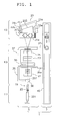
- FIG. 1 is a schematic view of a yarn winding unit arranged in an automatic winder according to one embodiment of the present invention.
- the automatic winder for example, is configured by a plurality of yarn winding units (yarn winding device) 1, a machine control device (not illustrated) adapted to set a winding condition or the like to the great number of yarn winding units 1, and an automatic doffing device (not illustrated) .
- the automatic doffing device moves to the yarn winding unit 1 that issued a doffing request signal, collects a package 205, attaches a new winding bobbin 203 to the relevant yarn winding unit 1 and performs a predetermined yarn hooking operation.
- the winding bobbin 203 is a member that becomes a core of the package 205, and is made of paper or plastic.
- the yarn winding unit 1 includes a yarn winding main body 5 and a unit frame 7.
- the yarn winding main body 5 carries out a winding operation, which is an operation of winding a yarn 207 of a yarn supplying bobbin 201 into the package 205 of a predetermined shape while traversing.
- the unit frame 7 supports the yarn winding main body 5.
- a unit control section 101 (to be described later) adapted to control the operation of the yarn winding main body 5 is arranged inside the unit frame 7.
- the yarn winding main body 5 includes a yarn supplying section (supplying section) 11, a yarn processing executing section 13, and a winding section 15.
- the yarn supplying section 11 is a device adapted to unwind the yarn 207 from the yarn supplying bobbin 201 and supply the same.
- the yarn supplying section 11 is a bobbin tray type, and a yarn supplying bobbin 201 is sequentially supplied to the yarn supplying section 11 of each winding unit 11 while being fixed to a tray.
- the yarn supplying section 11 includes an unwinding assisting device 19.
- the unwinding assisting device 19 includes a restricting member 20.
- the yarn processing executing section 13 is a device adapted to perform processing on the yarn 207 supplied from the yarn supplying section 11.
- the yarn processing executing section 13 includes a gate type tension applying device 21, a splicer 23, and a yarn clearer 25.
- the winding section 15 is a device adapted to wind the yarn 207 processed by the yarn processing executing section 13 into the package 205.
- the winding section 15 includes a cradle (package supporting section) 29 adapted to clamp the winding bobbin 203, and a traverse drum 31 adapted to traverse the yarn 207 (described later).
- the yarn supplying section 11, the yarn processing executing section 13, and the winding section 15 are arranged in such order from upstream towards downstream in a yarn travelling direction.
- the following devices are arranged in order from the upstream (from yarn supplying bobbin 201) in the yarn travelling direction on a yarn travelling path between the yarn supplying bobbin 201 and the traverse drum 31.
- the devices include the unwinding assisting device 19, the gate type tension applying device 21, the splicer 23, and the yarn clearer 25.
- the cradle 29 is a member for clamping the package 205, and includes a pair of cradle arms 29a, 29b.
- the cradle arms 29a, 29b are rotatably supported with a hinge shaft as a center, and can be swung in a direction of approaching to or separating from the traverse drum 31.
- Winding bobbin clamping sections 32a, 32b are rotatably attached at distal ends of the pair of cradle arms 29a, 29b, respectively.
- the winding bobbin clamping sections 32a, 32b are arranged to face each other, and can sandwich and clamp the winding bobbin 203.
- the winding bobbin clamping sections 32a, 32b are fitted to axial ends of the winding bobbin 203, and integrally rotated by the frictional force.
- the cradle 29 is configured to be able to attach the cone-shaped winding bobbin 203, where a larger diameter side is attached to the winding bobbin clamping section 32a and a smaller diameter side is attached to the winding bobbin clamping section 32b.
- FIG. 3 is a configuration diagram of an actuation air path.
- FIG. 4 is a schematic cross-sectional view of the package brake.
- the package brake 51 for applying brake on the rotation of the package 205 is arranged at a distal end of the cradle arm 29a.
- the package brake 51 includes a housing 52, a bearing sleeve 53, a rotation supporting section 54, a first spring 55, and a second spring 56.
- the bearing sleeve 53 is arranged so as to be movable and non-rotatable with respect to the housing 52.
- the rotation supporting section 54 is arranged on an inner side of the bearing sleeve 53, and is adapted to rotatably support a shaft extending from the winding bobbin clamping section 32a.
- the first spring 55 is arranged between a bottom surface of the housing 52 and the bearing sleeve 53.
- the first spring 55 applies an urging force towards the winding bobbin clamping section 32a with respect to the bearing sleeve 53.
- the second spring 56 is arranged between the bearing sleeve 53 and the rotation supporting section 44. With such configuration, the winding bobbin clamping section 32a can freely rotate with respect to the bearing sleeve 53 under a state compressed air is not supplied to the housing 52. When the compressed air is supplied into the housing 52, a contacting portion 53a arranged on the advancing bearing sleeve 53 makes contact with the winding bobbin clamping section 32a.
- the winding bobbin clamping section 32a is thereby sandwiched by the winding bobbin 203 and the bearing sleeve 53, and hence a frictional resistance is generated between the winding bobbin clamping section 32a and the contacting portion 53a. Therefore, the rotation of the winding bobbin clamping section 32a is braked, so that the rotation of the winding bobbin 203 (and package 205) can be stopped.
- the package brake 51 is configured to simultaneously carry out the application of brake force on the rotation of the winding bobbin clamping section 32a and the pushing of the winding bobbin clamping section 32a towards the winding bobbin 203.
- the package brake 51 increases the force of sandwiching the winding bobbin 203 between the winding bobbin clamping sections 32a, 32b if a force acting on the bearing sleeve 53 is smaller than or equal to a force of a prescribed magnitude, but does not apply brake force on the rotation of the winding bobbin 203.
- the package brake 51 applies brake force on the rotation of the winding bobbin if the force acting on the bearing sleeve 53 is greater than or equal to the prescribed magnitude.
- the prescribed magnitude is, for example, 10kgf (98,1 N) .
- the lift-up cylinder 57 is a device adapted to move the cradle 29 to separate the package 205 away from the traverse drum 31.
- the lift-up cylinder 57 is driven by air pressure.
- a cylinder rod of the lift-up cylinder 57 is coupled to the cradle arm 29a, where the lift-up cylinder 57 is extension driven so that the cradle 29 can be rotated in a direction of separating the package 205 away from the traverse drum 31.
- the actuation air path 40 for driving the package brake 51 and the lift-up cylinder 57 will be described using FIG. 4 .
- the actuation air path 40 includes a first air supply path 41 and a second air supply path 42.
- the first air supply path 41 is a circuit adapted to supply air for causing the cradle 29 to clamp the package 205 to the package brake 51 when winding the yarn into the package 205.
- the first air supply path 41 includes a first air supply source 63, and a first electromagnetic valve (first air control valve) 59 arranged between the first air supply source 63 and the package brake 51.
- the first electromagnetic valve 59 is a mechanism for switching supply/stop of the compressed air with respect to the package brake 51.
- a first air pipe 88 is extended from the first air supply source 63 to the package brake 51.
- the first electromagnetic valve 59 is electrically connected to the unit control section 101, where the unit control section 101 (brake lift-up control section 103 to be described later) can control the driving of the package brake 51 by sending a signal to the first electromagnetic valve 59.
- the first air supply source 63 is connected to the first electromagnetic valve 59.
- the pressure of the first air supply source 63 is weaker than the pressure of the air supplied during the brake actuation, and is less than or equal to 1/3 of the pressure of the air supplied during the brake actuation.
- the second air supply path 42 is a circuit adapted to drive the package brake 51 and the lift-up cylinder 57.
- the second air supply path 42 supplies air having a pressure higher than the air from the first air supply path 41 to the package brake 51 and the lift-up cylinder 57.
- the second air supply path 42 includes a second air supply source 65, and a second electromagnetic valve (second air control valve) 61 arranged between the second air supply source 65 and the lift-up cylinder 57.
- the second electromagnetic valve 61 is a mechanism for switching supply/stop of the compressed air with respect to the lift-up cylinder 57.
- a second air pipe 89 is extended from the second air supply source 65 to the lift-up cylinder 57.
- the second electromagnetic valve 61 is electrically connected to the unit control section 101, where the unit control section 101 (brake lift-up control section 103 to be described later) can control the driving of the lift-up cylinder 57 by sending a signal to the second electromagnetic valve 61.
- the second air supply source 65 is connected to the second electromagnetic valve 61.
- the air pressure of the second air supply source 65 is a pressure of about three times that of the first air supply source 63, and is about the same extent as the air pressure supplied during the brake actuation of the prior art.
- the first air supply path 41 further includes an air switching valve 67 arranged between the first electromagnetic valve 59 and the package brake 51, and connected to the first electromagnetic valve 59 and the second electromagnetic valve 61.
- a joint 69 is provided between the lift-up cylinder 57 and the second electromagnetic valve 61.
- the air switching valve 67 and the joint 69 are connected to each other by a third air pipe 90.
- the air switching valve 67 includes inlet ports 67a, 67b from the first electromagnetic valve 59 and the second electromagnetic valve 61, respectively, and also includes an outlet port 67c to the package brake 51.
- the joint 69 includes an inlet port 69a from the second electromagnetic valve 61, an outlet port 69b to the lift-up cylinder 57, and an outlet port 69c to the air switching valve 67.
- the air switching valve 67 is, for example, a shuttle valve, and has a structure of passing either one of the air having higher pressure supplied to the inlet ports 67a, 67b through the outlet port 67c. Backflow does not occur with such structure.
- a spiral-shaped traverse groove 31a is formed on a peripheral surface of the traverse drum 31, where the yarn 207 is traversed by the traverse groove 31a.
- a drum driving motor 97 and a motor control section 99 (to be described later) for rotating the traverse drum 31 are connected to the traverse drum 31.
- the unwinding assisting device 19 is a device adapted to assist the unwinding of the yarn from the yarn supplying bobbin 201 by lowering the restricting member 20 to be placed over a core tube in cooperation with the unwinding of the yarn from the yarn supplying bobbin 201.
- the restricting member 20 makes contact with a balloon formed at an upper part of the yarn supplying bobbin 201 by the rotation of the yarn unwound from the yarn supplying bobbin 201 and the centrifugal force, and applies an appropriate tension on the relevant balloon to assist the unwinding of the yarn.
- a first driving section 75 is provided to drive the unwinding assisting device 19.
- the first driving section 75 raises and lowers the unwinding assisting device 19 based on a drive signal from the unit control section 101.
- the gate type tension applying device 21 is a device adapted to apply a prescribed tension on the travelling yarn 207.
- the gate type tension applying device 21 is configured by a fixed comb tooth and a movable comb tooth.
- a second driving section 77 is provided to drive the movable comb tooth of the gate type tension applying device 21.
- the second driving section 77 is, for example, a rotary type solenoid, and is able to switch between a state in which the comb teeth are meshed and a state in which the comb teeth are released.
- the splicer 23 is a device adapted to join the yarn 207 from the yarn supplying bobbin 201 and the yarn 207 from the package 205 at the time of yarn cut or yarn breakage.
- the splicer 23 includes a plurality of levers such as a yarn guiding lever (not illustrated), where a series of operations of the plurality of levers is driven in a cam form.
- a third driving section 79 is provided to operate the plurality of levers of the splicer 23.
- the third driving section 79 drives the plurality of levers of the splicer 23 based on a drive signal from the unit control section 101.
- the yarn clearer 25 is a device adapted to detect a defect of the yarn 207.
- a signal corresponding to a thickness of the yarn 207 from the yarn clearer 25 is processed by an appropriate analyzer to detect a yarn defect such as a slub.
- the yarn clearer 25 includes a cutter (not illustrated) for cutting the yarn when the yarn defect is detected.
- the yarn clearer 25 also detects the travelling of the yarn 207.
- the yarn clearer 25 transmits a yarn breakage signal to the unit control section 101 if the travelling of the yarn 207 cannot be detected.
- a lower yarn guiding pipe 35 adapted to suck and catch the yarn 207 from the yarn supplying bobbin 201 and guide the same to the splicer 23 is provided on the lower side of the splicer 23, and an upper yarn guiding pipe 37 adapted to suck and catch the yarn 207 from the package 205 and guide the same to the splicer 23 is provided on the upper side.
- the lower yarn guiding pipe 35 is swingably attached with a shaft 35a as a center with respect to the unit frame 7, where a suction opening 36 is provided at the distal end.
- the upper yarn guiding pipe 37 is swingably attached with a shaft 37a as a center with respect to the unit frame 7, where a suction mouth 38 is provided at the distal end.
- a negative pressure source is connected to the lower yarn guiding pipe 35 and the upper yarn guiding pipe 37, so that suction flow can be generated at the suction opening 36 and the suction mouth 38.
- a fourth driving section 85 including a stepping motor is provided to drive the lower yarn guiding pipe 35.
- the fourth driving section 85 can drive the lower yarn guiding pipe 35 so as to swing about the shaft 35a.
- the fourth driving section 85 swings the lower yarn guiding pipe 35 based on a drive signal from the unit control section 101.
- the lower yarn guiding pipe 35 includes a lower yarn guiding pipe sensor 87 connected to the unit control section 101.
- the lower yarn guiding pipe sensor 87 is optically configured, for example, and transmits a yarn detection signal to the unit control section 101 when detecting the yarn 207 sucked into the pipe.
- a fifth driving section 91 including a stepping motor is provided to drive the upper yarn guiding pipe 37.
- the fifth driving section 91 can drive the upper yarn guiding pipe 37 so as to swing about the shaft 37a.
- the fifth driving section 91 can swing the upper yarn guiding pipe 37 based on a drive signal from the unit control section 101.
- the upper yarn guiding pipe 37 includes an upper yarn guiding pipe sensor 93.
- the upper yarn guiding pipe sensor 93 is optically configured, for example, and transmits a yarn detection signal to the unit control section 101 when detecting the yarn 207 sucked into the pipe.
- the upper yarn guiding pipe 37 is swung from bottom to top with the shaft 37a as a center from a position illustrated in FIG. 1 to suck and catch the yarn 207 from the reversely rotating package 205, and is further swung from top to bottom with the shaft 37a as a center to guide the yarn 207 to the splicer 23.
- the lower yarn guiding pipe 35 then sucks and catches the yarn 207 from the yarn supplying bobbin 201 at the position illustrated in FIG. 1 , and is then swung from bottom to top with the shaft 35a as a center to guide the yarn 207 to the splicer 23.
- the splicer 23 joins the two yarns 207 guided in such manner through a predetermined yarn joining operation.
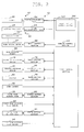
- FIG. 2 is a block diagram illustrating a control configuration of the yarn winding unit.
- the unit control section 101 includes a CPU (Central Processing Unit), which is an arithmetic processing unit, a ROM (Read Only Memory) adapted to store a control program to be executed by the CPU and data to be used in the control program, a RAM adapted to temporarily storing data during the program execution, and an I/O port.
- a CPU Central Processing Unit
- ROM Read Only Memory
- the control program stored in the ROM is read by the CPU and executed by the CPU, the control program controls each configuration of the yarn winding main body 5 using a hardware such as the CPU.
- the unit control section 101 includes a brake lift-up control section 103, and a winding control section 107.
- Various types of control programs are stored in the ROM of the unit control section 101, where the hardware such as the CPU of the unit control section 101 can be operated as the brake lift-up control section 103 and the winding control section 107 by executing the control program.
- the brake lift-up control section 103 immediately drives the lift-up cylinder 57 through the second electromagnetic valve 61 when the yarn breakage is detected or when the yarn clearer 25 detects the yarn defect and the yarn is disconnected, and performs a control to lift up the package 205 to separate away it from the traverse drum 31, and simultaneously stops the rotation of the package 205 by the package brake 51.
- the winding control section 107 controls the rotation of the traverse drum 31 for driving the package 205.
- An output shaft of the drum driving motor 97 is coupled to the traverse drum 31, and the drum driving motor 97 is controlled by the motor control section 99.
- the motor control section 99 controls rotation/stop of the drum driving motor 97 based on a signal from the unit control section 101.
- a drum rotation sensor 68 is attached to the traverse drum 31, where such drum rotation sensor 68 is electrically connected to the unit control section 101.
- the drum rotation sensor 68 is configured as a magnet sensor, for example, and is configured to transmit a rotation pulse signal to the unit control section 101 every time the traverse drum 31 rotates a prescribed angle.
- the unit control section 101 measures number of pulses per time to acquire the rotation speed of the traverse drum 31.
- the brake lift-up control section 103 of the unit control section 101 opens the first electromagnetic valve 59 and closes the second electromagnetic valve 61. Therefore, the air from the first air supply source 63 is supplied to the package brake 51, as illustrated with a solid line arrow of FIG. 3 .
- the bearing sleeve 53 urges the winding bobbin clamping section 32a in this state by the urging force from the first spring 55 through the second spring 56 and the low pressure air from the first air supply source 63. Therefore, the winding bobbin 203 is sandwiched between the winding bobbin clamping section 32a and the winding bobbin clamping section 32b.
- the contacting portion 53a of the bearing sleeve 53 in this case does not make contact with the winding bobbin clamping section 32a, and thus brake force is not applied by the brake.
- the paper tube clamping force is about 1.6 times, for example, that of the prior art.
- the winding bobbin clamping section 32a is rotatable in this case, whereby the winding bobbin 203 is also rotatable.
- the load of the spring is preferably between 1.5 and 2.0 kgf (15 and 20 N), and is preferably smaller than or equal to 3.0 kgf (30 N) taking the detachment of the package 205 by a human into consideration.
- the lift-up of the cradle 29 is carried out at the same time as the stopping of the winding rotation of the package 205.
- the lift-up is carried out to avoid the yarn from being damaged by the friction caused from the rotational difference of the package 205 and the traverse drum 31.
- the brake lift-up control section 103 of the unit control section 101 opens the second electromagnetic valve 61.
- the air from the second air supply source 65 is supplied to the package brake 51 and the lift-up cylinder 57.
- the lift-up cylinder 57 lifts up the cradle 29 to separate away from the traverse drum 31. Since the package brake 51 is actuated, the rotation of the package 205 is stopped.
- the operation in the package brake 51 will be more specifically described.
- the air switching valve 67 which is a shuttle valve, switches the conduction of air from the low pressure air from the first electromagnetic valve 59 to the high pressure air from the second electromagnetic valve 61 when receiving the high pressure air.
- the high pressure air is supplied to the package brake 51.
- the bearing sleeve 53 advances towards the winding bobbin 203 with a stronger force.
- the movement of the winding bobbin clamping section 32a is restricted by the winding bobbin 203, so that the winding bobbin clamping section 32a is sandwiched by the winding bobbin 203 and the bearing sleeve 53.
- the contacting portion 53a of the bearing sleeve 53 supported in a non-rotatable manner by the cradle 29 makes contact with and frictionally engages with the winding bobbin clamping section 32a, and hence the braking force for braking the rotation of the winding bobbin clamping section 32a is generated.
- the bearing sleeve 53 In the braking operation described above, the bearing sleeve 53 generates the pushing force of pushing the winding bobbin clamping section 32a in a direction of approaching the winding bobbin clamping section 32b, so that the winding bobbin 203 becomes strongly sandwiched by the winding bobbin clamping sections 32a, 32b, and the coupling of the winding bobbin 203 and the winding bobbin clamping sections 32a, 32b becomes stronger. As a result, the rotation of the winding bobbin 203 is stopped.
- the braking force is obtained by the elastic force of the first spring 55 and the supplied high pressure air, and the paper tube clamping force is about the same extent as in the prior art, for example.
- the yarn winding unit 1 (one example of yarn winding device) is a device adapted to wind a yarn from a supplying section to form a package, the device includes the cradle 29 (one example of package supporting section) and the actuation air path 40 (one example of actuation air path).
- the cradle 29 includes the winding bobbin clamping section 32a (one example of clamping section) for sandwiching and clamping the package 205, and the package brake 51 (one example of brake section) for controlling the clamping force and the braking of the winding bobbin clamping section 32a in accordance with the supplied air pressure.
- the actuation air path 40 includes a first air supply path 41 adapted to supply the first air for supplying the clamping force for the package brake 51 to rotatably support the package 205 through the winding bobbin clamping section 32a to the package brake 51, and a second air supply path 42 adapted to supply the second air for the package brake 51 to brake and stop the package 205 through the winding bobbin clamping section 32a to the package brake 51.
- the package brake 51 is actuated by the first air from the first air supply path 41 of the actuation air path 40 to rotatably support the package 205 during the yarn winding operation. As a result, a package of high quality winding state can be formed.
- the second air supply path 42 supplies the second air to the package brake 51.
- the package brake 51 thereby applies brake force to stop the package 205.
- the yarn winding unit 1 may further include the first spring 55 (one example of elastic member).
- the first spring 55 is arranged on the cradle 29, and is adapted to generate the elastic force for assisting the package brake 51 to rotatably support the package 205.
- the supply of the first air to the package brake 51 is stopped. Since the elastic force of the first spring 55 can be set relatively small by simultaneously using the first air, the operability in detaching the package does not lower.
- the yarn winding unit 1 may further include the lift-up cylinder 57 (one example of lifter) adapted to lift up the cradle 29.
- the second air supply path 42 supplies the second air to the package brake 51 and also supplies the second air to the lift-up cylinder 57.
- the first air supply path 41 may include the first air supply source 63 (one example of first air supply source) and the first electromagnetic valve 59 (one example of first air control valve) arranged between the first air supply source 63 and the package brake 51.
- the second air supply path 42 may include the second air supply source 65 (one example of second air supply source) and the second electromagnetic valve 61 (one example of second air control valve) arranged between the second air supply source 65 and the lift-up cylinder 57.
- the first air supply path 41 may also include the air switching valve 67 (one example of air switching valve), arranged between the first electromagnetic valve 59 and the package brake 51, and adapted to include the input port 67a connected to the first electromagnetic valve 59, the input port 67b connected to the second electromagnetic valve 61, and the output port 67c for outputting air from the first air supply source 63 or the second air supply source 65 to supply to the package brake 51.
- the first air from the first air supply source 63 of the first air supply path 41 is supplied to the package brake 51 through the first electromagnetic valve 59 during the package winding operation.
- the second air from the second air supply source 65 is supplied to the lift-up cylinder 57 through the second electromagnetic valve 61, and furthermore, supplied to the package brake 51 through the second electromagnetic valve 61 and the air switching valve 67.
- the air switching valve 67 may supply only the air of higher pressure of the supplied air to the package brake 51. Therefore, the first air is supplied to the package brake 51 if the first air is supplied from the first air supply source 63 to the air switching valve 67, and the second air is supplied to the package brake 51 if the second air is supplied from the second air supply source 65 to the air switching valve 67.
- another further independent low pressure air supplying section may be arranged with respect to the actuation air path in which separate independent air supply paths are connected to the brake and the lifter. The air is supplied from the low pressure air supply section to the brake during the winding operation.
- the present invention can be widely applied to a yarn winding device adapted to wind a yarn to form a package.
Landscapes
- Engineering & Computer Science (AREA)
- Quality & Reliability (AREA)
- Replacing, Conveying, And Pick-Finding For Filamentary Materials (AREA)
- Spinning Or Twisting Of Yarns (AREA)
- Winding Filamentary Materials (AREA)
Claims (5)
- Garnspulvorrichtung (1), die dafür ausgelegt ist, ein Garn (207) von einem Zulieferabschnitt (11) aufzuspulen, um eine Auflaufspule (205) zu bilden, welche Garnspulvorrichtung (1) enthält:einen Auflaufspulenhalteabschnitt (29);einen Klemmabschnitt (32a, 32b), der an dem Auflaufspulenhalteabschnitt (29) angeordnet ist und dafür ausgelegt ist, die Auflaufspule (205) durch Luftkraft drehbar zu klemmen;einen Klemmkraftanlegeabschnitt (51), der für ausgelegt ist, an einen Klemmabschnitt (32a, 32b) eine Klemmkraft anzulegen; undeinen ersten Luftversorgungsweg (41), der dafür ausgelegt ist, die für den Klemmabschnitt (32a, 32b) erforderliche Luft zu liefern, um die Auflaufspule (205) an einen Klemmkraftanlegeabschnitt (51) zu klemmen, dadurch gekennzeichnet, dass der Klemmkraftanlegeabschnitt (51) ferner ein elastisches Element (55) aufweist, welches dafür ausgelegt ist, eine elastische Kraft zu erzeugen, um den Klemmabschnitt (32a, 32b) dabei zu unterstützen, die Auflaufspule (205) drehbar zu klemmen.
- Garnspulvorrichtung (1) nach Anspruch 1,
dadurch gekennzeichnet, dass
der Klemmkraftanlegeabschnitt (51) ein Bremsabschnitt (51) ist, der an dem Auflaufspulenhalteabschnitt (29) vorgesehen ist und dafür ausgelegt ist, durch Luftdruck eine Bremskraft an den Klemmabschnitt (32a, 32b) anzulegen; und
ein zweiter Luftversorgungsweg (42), der dafür ausgelegt ist, einen zweiten Luftstrom für den Klemmabschnitt (32a, 32b) an den Bremsabschnitt (51) zu liefern, um eine Bremskraft anzulegen und die Auflaufspule (205) zu stoppen, des weiteren vorgesehen ist. - Garnspulvorrichtung nach Anspruch 1 oder 2,
dadurch gekennzeichnet, dass sie enthält:einen Hubeinrichtung (57), die dafür ausgelegt ist, den Spulenhalteabschnitt (29) anzugeben, dadurch gekennzeichnet, dassder zweite Luftversorgungsweg (72) den zweiten Luftstrom zu dem Bremsabschnitt (51) liefert und ferner den zweiten Luftstrom zu der Hubeinrichtung (47) liefert. - Garnspulvorrichtung nach Anspruch 3,
dadurch gekennzeichnet, dass
der erste Luftversorgungsweg (41) eine erste Luftversorgungsquelle (63) und ein erstes Luftsteuerventil (59) aufweist, das zwischen der ersten Luftversorgungsquelle (63) und dem Bremsabschnitt (51) vorgesehen ist;
der zweite Luftversorgungsweg (43) eine zweite Luftversorgungsquelle (65) und ein zweites Luftsteuerventil (61) aufweist, das zwischen der zweiten Luftversorgungsquelle (65) und der Hubeinrichtung (57) angeordnet ist; und
der erste Luftversorgungsweg (41) ein Luftumschaltventil (67) zum Umschalten eines Luftstromweges aufweist,
wobei das Luftumschaltventil (67) zwischen dem ersten Luftsteuerventil (59) und dem Bremsabschnitt (51) angeordnet ist und so konfiguriert ist, dass es einen Eingangsanschluss (67a), der mit dem ersten Luftsteuerventil (59) verbunden ist, einen Eingangsanschluss (67b), der mit dem zweiten Luftsteuerventil (61) verbunden ist, und einen Ausgangsanschluss zum Ausgeben von Luft von der ersten Luftversorgungsquelle (63) oder der zweiten Luftversorgungsquelle (65) und Liefern der Luft zu dem Bremsabschnitt (51) enthält. - Garnspulvorrichtung Anspruch 4, dadurch gekennzeichnet, dass das Luftumschaltventil (67) nur Luft mit einem höheren Druck der gelieferten Luft zu dem Bremsabschnitt (51) liefert.
Applications Claiming Priority (1)
| Application Number | Priority Date | Filing Date | Title |
|---|---|---|---|
| JP2011206414A JP2013067469A (ja) | 2011-09-21 | 2011-09-21 | 糸巻取装置 |
Publications (3)
| Publication Number | Publication Date |
|---|---|
| EP2573024A2 EP2573024A2 (de) | 2013-03-27 |
| EP2573024A3 EP2573024A3 (de) | 2014-03-19 |
| EP2573024B1 true EP2573024B1 (de) | 2015-09-23 |
Family
ID=46508274
Family Applications (1)
| Application Number | Title | Priority Date | Filing Date |
|---|---|---|---|
| EP12176223.1A Active EP2573024B1 (de) | 2011-09-21 | 2012-07-12 | Garnwicklungsvorrichtung |
Country Status (3)
| Country | Link |
|---|---|
| EP (1) | EP2573024B1 (de) |
| JP (1) | JP2013067469A (de) |
| CN (1) | CN103010820B (de) |
Families Citing this family (8)
| Publication number | Priority date | Publication date | Assignee | Title |
|---|---|---|---|---|
| CN103290540A (zh) * | 2013-06-18 | 2013-09-11 | 海宁市盛祥线业有限公司 | 一种包覆丝机上卷收筒的调节装置 |
| JP2018065637A (ja) * | 2016-10-18 | 2018-04-26 | 村田機械株式会社 | 糸巻取装置 |
| JP2018065638A (ja) * | 2016-10-18 | 2018-04-26 | 村田機械株式会社 | 糸巻取装置及びパッケージ減速方法 |
| CN108750804B (zh) * | 2018-06-05 | 2024-01-05 | 青岛宏大纺织机械有限责任公司 | 一种络筒机卷绕支撑装置 |
| JP2019218961A (ja) * | 2018-06-15 | 2019-12-26 | 村田機械株式会社 | ソレノイドバルブユニット及び自動ワインダ |
| CN109264500B (zh) * | 2018-11-20 | 2024-07-19 | 广东溢达纺织有限公司 | 络筒机用气动摇架机构以及络筒装置 |
| IT201900009153A1 (it) * | 2019-06-17 | 2020-12-17 | Fosber Spa | Braccio per uno svolgitore e svolgitore comprendente detto braccio |
| CN114101539B (zh) * | 2021-11-24 | 2023-08-15 | 南通理工学院 | 一种电磁辊生产使用的铜线自动编排装置 |
Family Cites Families (7)
| Publication number | Priority date | Publication date | Assignee | Title |
|---|---|---|---|---|
| CN2219282Y (zh) * | 1995-03-08 | 1996-02-07 | 中国纺织大学 | 卷绕机夹头夹紧保护装置 |
| DE19650932A1 (de) * | 1996-12-07 | 1998-06-10 | Schlafhorst & Co W | Kreuzspulen herstellende Textilmaschine |
| JP2000203763A (ja) | 1999-01-13 | 2000-07-25 | Murata Mach Ltd | 巻取管支持装置 |
| DE102006050140A1 (de) * | 2006-10-25 | 2008-04-30 | Oerlikon Textile Gmbh & Co. Kg | Spulenbremse für eine Spulvorrichtung einer Kreuzspulen herstellenden Textilmaschine |
| CN101195452B (zh) * | 2006-12-04 | 2012-05-02 | 天津宏大纺织机械有限公司 | 筒子支撑架的升降装置 |
| JP2010058955A (ja) * | 2008-09-05 | 2010-03-18 | Murata Machinery Ltd | パッケージブレーキと、これを備えた自動ワインダ |
| JP2011195216A (ja) * | 2010-03-17 | 2011-10-06 | Murata Machinery Ltd | 糸巻取機 |
-
2011
- 2011-09-21 JP JP2011206414A patent/JP2013067469A/ja not_active Withdrawn
-
2012
- 2012-07-12 EP EP12176223.1A patent/EP2573024B1/de active Active
- 2012-08-06 CN CN201210282194.XA patent/CN103010820B/zh active Active
Also Published As
| Publication number | Publication date |
|---|---|
| EP2573024A2 (de) | 2013-03-27 |
| EP2573024A3 (de) | 2014-03-19 |
| CN103010820A (zh) | 2013-04-03 |
| CN103010820B (zh) | 2016-08-24 |
| JP2013067469A (ja) | 2013-04-18 |
Similar Documents
| Publication | Publication Date | Title |
|---|---|---|
| EP2573024A2 (de) | Garnwicklungsvorrichtung | |
| EP2641859A1 (de) | Wicklungsvorrichtung | |
| JP5287992B2 (ja) | 糸巻取装置 | |
| EP2511216B1 (de) | Garnwickelvorrichtung und Garnentnahmeverfahren | |
| EP2738129B1 (de) | Garnwickelmaschine und Textilmaschine mit der Garnwickelmaschine | |
| JP2013067467A (ja) | 糸継装置及び糸巻取装置 | |
| JP2018030722A (ja) | 綾巻きパッケージを製造する繊維機械の作業ユニット用の糸スプライシング装置 | |
| JP2009286608A (ja) | 自動ワインダ | |
| EP1457446B9 (de) | Vorrichtung zur Fadenspannungsregelung und zur Beseitigung von Fadenlockerungen in einer Garnwickeleinrichtung | |
| EP2738127A2 (de) | Garnwickelmaschine und Garnentnahmeverfahren | |
| JP2013067464A (ja) | 糸継装置及び糸巻取装置 | |
| EP2573031A2 (de) | Garnverarbeitungsvorrichtung und Garnaufwickelvorrichtung | |
| EP2960196B1 (de) | Garnwicklungsmaschine | |
| CN109422136B (zh) | 纱线卷取机 | |
| EP2738128B1 (de) | Garnwicklungsmaschine | |
| EP2078691A2 (de) | Knickverhinderungsvorrichtung und automatischer Wickler damit | |
| JP2010037083A (ja) | 糸巻取機及び自動ワインダ | |
| EP3689803B1 (de) | Vorrichtung zum aufspulen eines fadens | |
| JP2016155639A (ja) | 糸巻取装置及び繊維機械 | |
| JP2014218314A (ja) | 糸巻取機 | |
| EP2567920B1 (de) | Garnwicklungsmaschine | |
| CN116265362A (zh) | 纱线卷取机 | |
| EP2853510B1 (de) | Versorgungsfahrzeug einer Textilmaschine | |
| JP2019142654A (ja) | 糸継装置、巻取ユニット及び繊維機械 | |
| JP2006089150A (ja) | 糸巻取機における糸継方法、及び糸巻取機 |
Legal Events
| Date | Code | Title | Description |
|---|---|---|---|
| PUAI | Public reference made under article 153(3) epc to a published international application that has entered the european phase |
Free format text: ORIGINAL CODE: 0009012 |
|
| AK | Designated contracting states |
Kind code of ref document: A2 Designated state(s): AL AT BE BG CH CY CZ DE DK EE ES FI FR GB GR HR HU IE IS IT LI LT LU LV MC MK MT NL NO PL PT RO RS SE SI SK SM TR |
|
| AX | Request for extension of the european patent |
Extension state: BA ME |
|
| PUAL | Search report despatched |
Free format text: ORIGINAL CODE: 0009013 |
|
| AK | Designated contracting states |
Kind code of ref document: A3 Designated state(s): AL AT BE BG CH CY CZ DE DK EE ES FI FR GB GR HR HU IE IS IT LI LT LU LV MC MK MT NL NO PL PT RO RS SE SI SK SM TR |
|
| AX | Request for extension of the european patent |
Extension state: BA ME |
|
| RIC1 | Information provided on ipc code assigned before grant |
Ipc: B65H 63/036 20060101ALI20140212BHEP Ipc: B65H 54/553 20060101AFI20140212BHEP |
|
| 17P | Request for examination filed |
Effective date: 20140822 |
|
| RBV | Designated contracting states (corrected) |
Designated state(s): AL AT BE BG CH CY CZ DE DK EE ES FI FR GB GR HR HU IE IS IT LI LT LU LV MC MK MT NL NO PL PT RO RS SE SI SK SM TR |
|
| GRAP | Despatch of communication of intention to grant a patent |
Free format text: ORIGINAL CODE: EPIDOSNIGR1 |
|
| INTG | Intention to grant announced |
Effective date: 20150331 |
|
| GRAS | Grant fee paid |
Free format text: ORIGINAL CODE: EPIDOSNIGR3 |
|
| GRAA | (expected) grant |
Free format text: ORIGINAL CODE: 0009210 |
|
| AK | Designated contracting states |
Kind code of ref document: B1 Designated state(s): AL AT BE BG CH CY CZ DE DK EE ES FI FR GB GR HR HU IE IS IT LI LT LU LV MC MK MT NL NO PL PT RO RS SE SI SK SM TR |
|
| REG | Reference to a national code |
Ref country code: GB Ref legal event code: FG4D |
|
| REG | Reference to a national code |
Ref country code: CH Ref legal event code: EP |
|
| REG | Reference to a national code |
Ref country code: AT Ref legal event code: REF Ref document number: 751113 Country of ref document: AT Kind code of ref document: T Effective date: 20151015 |
|
| REG | Reference to a national code |
Ref country code: IE Ref legal event code: FG4D |
|
| REG | Reference to a national code |
Ref country code: DE Ref legal event code: R096 Ref document number: 602012010896 Country of ref document: DE |
|
| REG | Reference to a national code |
Ref country code: NL Ref legal event code: MP Effective date: 20150923 |
|
| PG25 | Lapsed in a contracting state [announced via postgrant information from national office to epo] |
Ref country code: GR Free format text: LAPSE BECAUSE OF FAILURE TO SUBMIT A TRANSLATION OF THE DESCRIPTION OR TO PAY THE FEE WITHIN THE PRESCRIBED TIME-LIMIT Effective date: 20151224 Ref country code: NO Free format text: LAPSE BECAUSE OF FAILURE TO SUBMIT A TRANSLATION OF THE DESCRIPTION OR TO PAY THE FEE WITHIN THE PRESCRIBED TIME-LIMIT Effective date: 20151223 Ref country code: LT Free format text: LAPSE BECAUSE OF FAILURE TO SUBMIT A TRANSLATION OF THE DESCRIPTION OR TO PAY THE FEE WITHIN THE PRESCRIBED TIME-LIMIT Effective date: 20150923 Ref country code: LV Free format text: LAPSE BECAUSE OF FAILURE TO SUBMIT A TRANSLATION OF THE DESCRIPTION OR TO PAY THE FEE WITHIN THE PRESCRIBED TIME-LIMIT Effective date: 20150923 Ref country code: FI Free format text: LAPSE BECAUSE OF FAILURE TO SUBMIT A TRANSLATION OF THE DESCRIPTION OR TO PAY THE FEE WITHIN THE PRESCRIBED TIME-LIMIT Effective date: 20150923 |
|
| REG | Reference to a national code |
Ref country code: LT Ref legal event code: MG4D |
|
| REG | Reference to a national code |
Ref country code: AT Ref legal event code: MK05 Ref document number: 751113 Country of ref document: AT Kind code of ref document: T Effective date: 20150923 |
|
| PG25 | Lapsed in a contracting state [announced via postgrant information from national office to epo] |
Ref country code: SE Free format text: LAPSE BECAUSE OF FAILURE TO SUBMIT A TRANSLATION OF THE DESCRIPTION OR TO PAY THE FEE WITHIN THE PRESCRIBED TIME-LIMIT Effective date: 20150923 Ref country code: RS Free format text: LAPSE BECAUSE OF FAILURE TO SUBMIT A TRANSLATION OF THE DESCRIPTION OR TO PAY THE FEE WITHIN THE PRESCRIBED TIME-LIMIT Effective date: 20150923 Ref country code: HR Free format text: LAPSE BECAUSE OF FAILURE TO SUBMIT A TRANSLATION OF THE DESCRIPTION OR TO PAY THE FEE WITHIN THE PRESCRIBED TIME-LIMIT Effective date: 20150923 |
|
| PG25 | Lapsed in a contracting state [announced via postgrant information from national office to epo] |
Ref country code: NL Free format text: LAPSE BECAUSE OF FAILURE TO SUBMIT A TRANSLATION OF THE DESCRIPTION OR TO PAY THE FEE WITHIN THE PRESCRIBED TIME-LIMIT Effective date: 20150923 |
|
| REG | Reference to a national code |
Ref country code: DE Ref legal event code: R082 Ref document number: 602012010896 Country of ref document: DE Representative=s name: WEICKMANN & WEICKMANN PATENTANWAELTE - RECHTSA, DE Ref country code: DE Ref legal event code: R082 Ref document number: 602012010896 Country of ref document: DE Representative=s name: WEICKMANN & WEICKMANN PATENT- UND RECHTSANWAEL, DE |
|
| PG25 | Lapsed in a contracting state [announced via postgrant information from national office to epo] |
Ref country code: EE Free format text: LAPSE BECAUSE OF FAILURE TO SUBMIT A TRANSLATION OF THE DESCRIPTION OR TO PAY THE FEE WITHIN THE PRESCRIBED TIME-LIMIT Effective date: 20150923 Ref country code: SK Free format text: LAPSE BECAUSE OF FAILURE TO SUBMIT A TRANSLATION OF THE DESCRIPTION OR TO PAY THE FEE WITHIN THE PRESCRIBED TIME-LIMIT Effective date: 20150923 Ref country code: IS Free format text: LAPSE BECAUSE OF FAILURE TO SUBMIT A TRANSLATION OF THE DESCRIPTION OR TO PAY THE FEE WITHIN THE PRESCRIBED TIME-LIMIT Effective date: 20160123 Ref country code: CZ Free format text: LAPSE BECAUSE OF FAILURE TO SUBMIT A TRANSLATION OF THE DESCRIPTION OR TO PAY THE FEE WITHIN THE PRESCRIBED TIME-LIMIT Effective date: 20150923 Ref country code: ES Free format text: LAPSE BECAUSE OF FAILURE TO SUBMIT A TRANSLATION OF THE DESCRIPTION OR TO PAY THE FEE WITHIN THE PRESCRIBED TIME-LIMIT Effective date: 20150923 |
|
| PG25 | Lapsed in a contracting state [announced via postgrant information from national office to epo] |
Ref country code: PL Free format text: LAPSE BECAUSE OF FAILURE TO SUBMIT A TRANSLATION OF THE DESCRIPTION OR TO PAY THE FEE WITHIN THE PRESCRIBED TIME-LIMIT Effective date: 20150923 Ref country code: AT Free format text: LAPSE BECAUSE OF FAILURE TO SUBMIT A TRANSLATION OF THE DESCRIPTION OR TO PAY THE FEE WITHIN THE PRESCRIBED TIME-LIMIT Effective date: 20150923 Ref country code: RO Free format text: LAPSE BECAUSE OF FAILURE TO SUBMIT A TRANSLATION OF THE DESCRIPTION OR TO PAY THE FEE WITHIN THE PRESCRIBED TIME-LIMIT Effective date: 20150923 Ref country code: PT Free format text: LAPSE BECAUSE OF FAILURE TO SUBMIT A TRANSLATION OF THE DESCRIPTION OR TO PAY THE FEE WITHIN THE PRESCRIBED TIME-LIMIT Effective date: 20160125 |
|
| REG | Reference to a national code |
Ref country code: DE Ref legal event code: R097 Ref document number: 602012010896 Country of ref document: DE |
|
| PLBE | No opposition filed within time limit |
Free format text: ORIGINAL CODE: 0009261 |
|
| STAA | Information on the status of an ep patent application or granted ep patent |
Free format text: STATUS: NO OPPOSITION FILED WITHIN TIME LIMIT |
|
| 26N | No opposition filed |
Effective date: 20160624 |
|
| PG25 | Lapsed in a contracting state [announced via postgrant information from national office to epo] |
Ref country code: DK Free format text: LAPSE BECAUSE OF FAILURE TO SUBMIT A TRANSLATION OF THE DESCRIPTION OR TO PAY THE FEE WITHIN THE PRESCRIBED TIME-LIMIT Effective date: 20150923 |
|
| PG25 | Lapsed in a contracting state [announced via postgrant information from national office to epo] |
Ref country code: SI Free format text: LAPSE BECAUSE OF FAILURE TO SUBMIT A TRANSLATION OF THE DESCRIPTION OR TO PAY THE FEE WITHIN THE PRESCRIBED TIME-LIMIT Effective date: 20150923 |
|
| PG25 | Lapsed in a contracting state [announced via postgrant information from national office to epo] |
Ref country code: BE Free format text: LAPSE BECAUSE OF FAILURE TO SUBMIT A TRANSLATION OF THE DESCRIPTION OR TO PAY THE FEE WITHIN THE PRESCRIBED TIME-LIMIT Effective date: 20150923 |
|
| REG | Reference to a national code |
Ref country code: CH Ref legal event code: PL |
|
| GBPC | Gb: european patent ceased through non-payment of renewal fee |
Effective date: 20160712 |
|
| PG25 | Lapsed in a contracting state [announced via postgrant information from national office to epo] |
Ref country code: MC Free format text: LAPSE BECAUSE OF FAILURE TO SUBMIT A TRANSLATION OF THE DESCRIPTION OR TO PAY THE FEE WITHIN THE PRESCRIBED TIME-LIMIT Effective date: 20150923 |
|
| PG25 | Lapsed in a contracting state [announced via postgrant information from national office to epo] |
Ref country code: FR Free format text: LAPSE BECAUSE OF NON-PAYMENT OF DUE FEES Effective date: 20160801 Ref country code: CH Free format text: LAPSE BECAUSE OF NON-PAYMENT OF DUE FEES Effective date: 20160731 Ref country code: LI Free format text: LAPSE BECAUSE OF NON-PAYMENT OF DUE FEES Effective date: 20160731 |
|
| REG | Reference to a national code |
Ref country code: FR Ref legal event code: ST Effective date: 20170331 |
|
| REG | Reference to a national code |
Ref country code: IE Ref legal event code: MM4A |
|
| PG25 | Lapsed in a contracting state [announced via postgrant information from national office to epo] |
Ref country code: GB Free format text: LAPSE BECAUSE OF NON-PAYMENT OF DUE FEES Effective date: 20160712 |
|
| PG25 | Lapsed in a contracting state [announced via postgrant information from national office to epo] |
Ref country code: IE Free format text: LAPSE BECAUSE OF NON-PAYMENT OF DUE FEES Effective date: 20160712 |
|
| PG25 | Lapsed in a contracting state [announced via postgrant information from national office to epo] |
Ref country code: LU Free format text: LAPSE BECAUSE OF NON-PAYMENT OF DUE FEES Effective date: 20160712 |
|
| PG25 | Lapsed in a contracting state [announced via postgrant information from national office to epo] |
Ref country code: SM Free format text: LAPSE BECAUSE OF FAILURE TO SUBMIT A TRANSLATION OF THE DESCRIPTION OR TO PAY THE FEE WITHIN THE PRESCRIBED TIME-LIMIT Effective date: 20150923 Ref country code: CY Free format text: LAPSE BECAUSE OF FAILURE TO SUBMIT A TRANSLATION OF THE DESCRIPTION OR TO PAY THE FEE WITHIN THE PRESCRIBED TIME-LIMIT Effective date: 20150923 Ref country code: HU Free format text: LAPSE BECAUSE OF FAILURE TO SUBMIT A TRANSLATION OF THE DESCRIPTION OR TO PAY THE FEE WITHIN THE PRESCRIBED TIME-LIMIT; INVALID AB INITIO Effective date: 20120712 |
|
| PG25 | Lapsed in a contracting state [announced via postgrant information from national office to epo] |
Ref country code: MK Free format text: LAPSE BECAUSE OF FAILURE TO SUBMIT A TRANSLATION OF THE DESCRIPTION OR TO PAY THE FEE WITHIN THE PRESCRIBED TIME-LIMIT Effective date: 20150923 Ref country code: TR Free format text: LAPSE BECAUSE OF FAILURE TO SUBMIT A TRANSLATION OF THE DESCRIPTION OR TO PAY THE FEE WITHIN THE PRESCRIBED TIME-LIMIT Effective date: 20150923 Ref country code: MT Free format text: LAPSE BECAUSE OF NON-PAYMENT OF DUE FEES Effective date: 20160731 |
|
| PG25 | Lapsed in a contracting state [announced via postgrant information from national office to epo] |
Ref country code: BG Free format text: LAPSE BECAUSE OF FAILURE TO SUBMIT A TRANSLATION OF THE DESCRIPTION OR TO PAY THE FEE WITHIN THE PRESCRIBED TIME-LIMIT Effective date: 20150923 |
|
| PG25 | Lapsed in a contracting state [announced via postgrant information from national office to epo] |
Ref country code: AL Free format text: LAPSE BECAUSE OF FAILURE TO SUBMIT A TRANSLATION OF THE DESCRIPTION OR TO PAY THE FEE WITHIN THE PRESCRIBED TIME-LIMIT Effective date: 20150923 |
|
| PGFP | Annual fee paid to national office [announced via postgrant information from national office to epo] |
Ref country code: IT Payment date: 20240619 Year of fee payment: 13 |
|
| PGFP | Annual fee paid to national office [announced via postgrant information from national office to epo] |
Ref country code: DE Payment date: 20240619 Year of fee payment: 13 |
|
| REG | Reference to a national code |
Ref country code: DE Ref legal event code: R119 Ref document number: 602012010896 Country of ref document: DE |
|
| PG25 | Lapsed in a contracting state [announced via postgrant information from national office to epo] |
Ref country code: DE Free format text: LAPSE BECAUSE OF NON-PAYMENT OF DUE FEES Effective date: 20260203 |