EP2573233A2 - Machine de dégarnissage et machine textile - Google Patents
Machine de dégarnissage et machine textile Download PDFInfo
- Publication number
- EP2573233A2 EP2573233A2 EP12182980A EP12182980A EP2573233A2 EP 2573233 A2 EP2573233 A2 EP 2573233A2 EP 12182980 A EP12182980 A EP 12182980A EP 12182980 A EP12182980 A EP 12182980A EP 2573233 A2 EP2573233 A2 EP 2573233A2
- Authority
- EP
- European Patent Office
- Prior art keywords
- winding
- tube
- lever
- end portion
- restricting
- Prior art date
- Legal status (The legal status is an assumption and is not a legal conclusion. Google has not performed a legal analysis and makes no representation as to the accuracy of the status listed.)
- Withdrawn
Links
Images


Classifications
-
- D—TEXTILES; PAPER
- D01—NATURAL OR MAN-MADE THREADS OR FIBRES; SPINNING
- D01H—SPINNING OR TWISTING
- D01H9/00—Arrangements for replacing or removing bobbins, cores, receptacles, or completed packages at paying-out or take-up stations ; Combination of spinning-winding machine
- D01H9/02—Arrangements for replacing or removing bobbins, cores, receptacles, or completed packages at paying-out or take-up stations ; Combination of spinning-winding machine for removing completed take-up packages and replacing by bobbins, cores, or receptacles at take-up stations; Transferring material between adjacent full and empty take-up elements
-
- B—PERFORMING OPERATIONS; TRANSPORTING
- B65—CONVEYING; PACKING; STORING; HANDLING THIN OR FILAMENTARY MATERIAL
- B65H—HANDLING THIN OR FILAMENTARY MATERIAL, e.g. SHEETS, WEBS, CABLES
- B65H54/00—Winding, coiling, or depositing filamentary material
- B65H54/02—Winding and traversing material on to reels, bobbins, tubes, or like package cores or formers
- B65H54/22—Automatic winding machines, i.e. machines with servicing units for automatically performing end-finding, interconnecting of successive lengths of material, controlling and fault-detecting of the running material and replacing or removing of full or empty cores
- B65H54/26—Automatic winding machines, i.e. machines with servicing units for automatically performing end-finding, interconnecting of successive lengths of material, controlling and fault-detecting of the running material and replacing or removing of full or empty cores having one or more servicing units moving along a plurality of fixed winding units
-
- B—PERFORMING OPERATIONS; TRANSPORTING
- B65—CONVEYING; PACKING; STORING; HANDLING THIN OR FILAMENTARY MATERIAL
- B65H—HANDLING THIN OR FILAMENTARY MATERIAL, e.g. SHEETS, WEBS, CABLES
- B65H67/00—Replacing or removing cores, receptacles, or completed packages at paying-out, winding, or depositing stations
- B65H67/04—Arrangements for removing completed take-up packages and or replacing by cores, formers, or empty receptacles at winding or depositing stations; Transferring material between adjacent full and empty take-up elements
- B65H67/0405—Arrangements for removing completed take-up packages or for loading an empty core
- B65H67/0417—Arrangements for removing completed take-up packages or for loading an empty core for loading an empty core
-
- B—PERFORMING OPERATIONS; TRANSPORTING
- B65—CONVEYING; PACKING; STORING; HANDLING THIN OR FILAMENTARY MATERIAL
- B65H—HANDLING THIN OR FILAMENTARY MATERIAL, e.g. SHEETS, WEBS, CABLES
- B65H67/00—Replacing or removing cores, receptacles, or completed packages at paying-out, winding, or depositing stations
- B65H67/06—Supplying cores, receptacles, or packages to, or transporting from, winding or depositing stations
- B65H67/068—Supplying or transporting empty cores
-
- B—PERFORMING OPERATIONS; TRANSPORTING
- B65—CONVEYING; PACKING; STORING; HANDLING THIN OR FILAMENTARY MATERIAL
- B65H—HANDLING THIN OR FILAMENTARY MATERIAL, e.g. SHEETS, WEBS, CABLES
- B65H2701/00—Handled material; Storage means
- B65H2701/30—Handled filamentary material
- B65H2701/31—Textiles threads or artificial strands of filaments
Definitions
- the present invention relates to a doffing apparatus used in textile machines such as automatic winders.
- the present invention more particularly relates to a doffing apparatus capable of accurately positioning a winding tube arranged at an unloading opening in a winding-tube tray to a specified position.
- JP 2008-162712 A A known doffing apparatus is described in JP 2008-162712 A .
- multiple winding devices 2 are arranged side-by-side in an automatic winder, and a doffing apparatus 6 is freely movable in the direction of arrangement of the winding devices 2.
- the doffing apparatus 6 has cradle arms 21 for holding a winding package P. When the cradle arms 21 are opened, a fully-wound winding package P held by the cradle arms 21 rolls down rearward to be loaded onto a transporting device 12.
- a chuck 66 grips and unloads an empty winding tube 9 from a box-shaped winding-tube tray 65 and puts the winding tube 9 between the cradle arms 21 for the cradle arms 21 to hold the winding tube 9. Subsequently, a yarn Y coming from a yarn supplying bobbin B is set around the winding tube 9 held by the cradle arms 21, and winding on the newly-mounted winding tube 9 is started.
- winding tubes used in an automatic winder or the like have a variation of approximately 5 millimeters (mm) in their axial length due to variations arising in the manufacturing process. Also, when the type of the winding tube to be used is changed from one to another depending on the type of the yarn to be wound, there can be a circumstance where winding tubes that differ from each other by approximately 5 mm in axial length are used consecutively.
- the distance between the opposite sidewalls of the winding-tube tray in the axial direction of the winding tube is set sufficiently large so that all the types of the winding tubes having different axial lengths can be accommodated in the winding-tube tray.
- a winding tube that is short in axial length can move freely between the two sidewalls of the winding-tube tray when the distance between the two sidewalls is relatively larger than the axial length of the winding tube. Accordingly, a position in the axial direction of the winding tube where the chuck holds the winding tube may vary. When the holding position varies, there can be a case where the winding tube is not positioned to a normal mounting position in the cradle arms at mounting of the winding tube into the cradle arms, and resulting into mounting failure.
- the winding-tube tray of the doffing apparatus of JP 2008-162712 A includes a positioning member.
- the winding tube is pressed against the positioning member to position the winding tube at a specified position.
- the winding-tube tray 65 is provided corresponding to each of the winding devices 2 in a machine body 61 arranged above the winding devices 2.
- This object is achieved by a doffing apparatus according to claim 1.
- the winding-tube tray as used in a conventional doffing apparatus described above may be displaced from the specified position in the winding device due to a manufacturing error, time-related degradation, or the like. In such a case, the winding tube cannot be positioned to the specified position because the position of the positioning member of the winding-tube tray is also displaced. If this happens, the winding tube will not be placed at the normal mounting position in the cradle arms.
- the conventional doffing apparatus described above also disadvantageously requires strict position adjustment between the winding device and the winding-tube tray at installation of the machine body. The inventive doffing apparatus avoids the above mentioned disadvantages.
- a doffing apparatus which travels to a desired one among a plurality of winding units arranged side-by-side, each of the winding units including a winding-tube tray and a winding-tube support member, and supplies a winding tube to the desired winding unit from the winding-tube tray of the desired winding unit, includes a winding-tube holding section that holds the winding tube and supplies the winding tube to the winding-tube supporting member of the winding unit; a restricting lever that comes into contact with a first-side end portion of the winding tube held by the winding-tube holding section thereby restricting a position of the first-side end portion of the winding tube; and a pressing lever that comes into contact with a second-side end portion being on opposite side of the first-side end portion of the winding tube restricted by the restricting lever and presses the second-side end portion of the winding tube against the restricting lever.
- a textile machine includes the above doffing apparatus and a plurality of winding units.
- the automatic winder 1 includes a plurality of winding devices (winding units) 2 arranged side-by-side, a yarn-feeding-bobbin supplying device 3 that supplies yarn supplying bobbins B to each of the winding devices 2, a doffing apparatus 6 that performs a doffing operation for each of the winding devices 2, a transporting device 12 that transports a winding package P undergone the doffing operation performed by the doffing apparatus 6, and a control device 8 that controls each of the winding devices 2, the doffing apparatus 6, and the like.
- the winding device 2 unwinds the yarn Y from the yarn supplying bobbin B and winds the yarn Y onto a winding tube 9 to form the winding package P.
- Cradle arms (winding-tube supporting member) 21 that rotatably hold the winding tube 9, and a drum 22 that causes the winding tube 9 held by the cradle arms 21 to rotate are arranged in an upper portion of the winding device 2.
- the cradle arms 21 are movable between a winding position (indicated by solid lines in FIG. 2 ) where the winding package P (or the winding tube 9 at start of winding) contacts the drum 22 and a dismounting position (indicated by long dashed double-short dashed lines in FIG. 2 ) where the winding package P is dismounted by the doffing apparatus 6.
- the cradle arms 21 include winding-tube holders 23, 23 for holding the winding tube 9 therebetween.
- One of the winding-tube holders 23 rocks in an axial direction of the drum 22 so that the winding tube 9 can be detachably mounted into the cradle arms 21.
- the drum 22 is coupled to a drive motor 25 controlled by a unit controller 24, and rotates at a high speed or low speeds.
- the unit controller 24 is communicably connected to the control device 8 and receives a value of the number of full-winding rotations from the control device 8.
- the unit controller 24 also controls winding of the yarn Y onto the winding tube 9 that is brought into contact with the drum 22 by controlling the rotation of the drum 22 in the following order. First, the drum 22 is rotated at a low speed for winding a cut yarn Y onto the winding package P; second, the drum 22 is rotated at a low speed for bunch winding the yarn Y onto the winding tube 9; and third, the drum 22 is rotated at a high speed for production winding the yarn Y onto the winding tube 9.
- the winding device 2 includes, on a downstream side along a yarn path, a yarn joining device 26 that performs yarn joining of the yarn Y, a yarn clearer 27 that includes a yarn cutting section 27a and detects a yarn defect, and a suction arm 28 that introduces the yarn Y to the yarn joining device 26 by sucking and catching the yarn Y, which is cut and coming from the yarn supplying bobbin B.
- the doffing apparatus 6 is capable of travelling above the winding devices 2 along a rail 7 arranged on the machine body 61.
- the doffing apparatus 6 stops at a specified position for that winding device 2 and performs the doffing operation.
- the doffing apparatus 6 includes a yarn clamping device 62 that is extendable to the suction arm 28, an opener 63 that moves and opens/closes the cradle arms 21, and a yarn handling lever 64 that pulls and guides the yarn Y toward the winding tube 9 held by the cradle arms 21.
- the yarn clamping device 62 includes a yarn-cutting-and-clamping section 62a capable of performing telescopic motion by the action of an air cylinder.
- the yarn-cutting-and-clamping section 62a cuts and clamps the yarn Y in conjunction with the telescopic motion.
- the yarn clamping device 62 is arranged in a lower portion of the doffing apparatus 6.
- the yarn clamping device 62 is swivelable in a radial direction of the drum 22. The yarn clamping device 62 swivels in such a manner as to lift the yarn Y to a position above the drum 22 and interpose the yarn Y between the drum 22 and the cradle arms 21.
- the opener 63 of the doffing apparatus 6 includes an opening lever 63b that is fixed to a pivot shaft 63a that projects from a side portion of the doffing apparatus 6 in the axial direction of the drum 22.
- the opening lever 63b includes at its leading end an opening piece 63c that comes into contact with a cradle lever 21a arranged on one of the cradle arms 21.
- the opening lever 63b is rockable in the axial direction of the drum 22.
- the opening lever 63b extends toward the cradle arms 21 and includes the opening piece 63c of which swiveling track crosses a swiveling track of the cradle lever 21a that swivels integrally with the cradle arms 21.
- the opener 63 with the opening piece 63c being in contact with the cradle lever 21a, swivels in a direction away from the drum 22, thereby moving the cradle arms 21 that hold the winding package P from the winding position to the dismounting position.
- the opener 63 then swivels toward the drum 22 to cause the cradle arms 21 to swivel from the dismounting position to the winding position, thereby bringing the winding tube 9 into contact with the drum 22.
- the opener 63 also rocks in the axial direction of the drum 22 to open and close the cradle arms 21 via the cradle lever 21a to allow doffing of the fully-wound package P and mounting of the winding tube 9.
- the yarn handling lever 64 of the doffing apparatus 6 includes at its leading end a yarn hook member.
- the yarn handling lever 64 is arranged on a side from which the yarn Y is introduced to the drum 22 and pivotable toward the winding tube 9.
- the yarn handling lever 64 hooks the yarn Y lifted by the yarn clamping device 62 by pivoting toward the winding tube 9 and pulls the yarn Y to the winding tube 9 in such a manner as to pinch the yarn Y between a large-diameter end of the winding tube 9 and one of the winding-tube holders 23.
- the winding-tube trays 65 each of which is arranged above a corresponding one of the winding devices 2 and stores a plurality of the winding tubes 9, are fixed to the machine body 61.
- the doffing apparatus 6 includes the chuck (winding-tube holding section) 66 that holds the winding tube 9 with a chuck claw at a leading end of the chuck 66 and conveys the winding tube 9 from the winding-tube tray 65 fixed onto the machine body 61 to the drum 22, and a separator 69 that causes a remainder of the winding tubes 9 other than the to-be-held winding tube 9 to retreat upward when the chuck 66 holds the to-be-held winding tube 9 so that the chuck 66 can hold and mount the held winding tube 9 into the cradle arms 21.
- the winding-tube tray 65 is inclined relative to a horizontal direction corresponding to an apparatus installation surface in such a manner that the front side of the winding-tube tray 65 is at a level lower than that of the rear side. Accordingly, the winding tubes 9 in the winding-tube tray 65 roll down toward the front side (toward an unloading opening 65d) to be accumulated.
- the winding-tube tray 65 has the unloading opening 65d through which the winding tubes 9 pass.
- the winding-tube tray 65 includes a pair of support lugs 65c, 65c.
- the support lugs 65c, 65c support the winding tube 9 when the winding tube 9 is placed at the unloading opening 65d.
- the support lugs 65c, 65c are upwardly urged by a not shown coil spring to contact with the winding-tube tray 65.
- the chuck 66 moves further downward against the urging force applied from the support lugs 65c, 65c while holding the winding tube 9 at the forward end in the winding-tube tray 65.
- the winding tube 9 is placed between the cradle arms 21 of the winding device 2 through the unloading opening 65d in the winding-tube tray 65.
- the winding tube 9 held by the chuck 66 includes a first-side end portion 9a which is on the left side in FIG. 4 and a second-side end portion 9b which is on the right side in FIG. 4 .
- the winding-tube tray 65 includes an L-shaped side wall portion 65a outside the first-side end portion 9a of the winding tube 9 and has an opening 65b that allows insertion of a portion of a restricting plate 71a of a restricting lever 71, which will be described later, therethrough.
- the opening 65b and the unloading opening 65d are in communication with each other.
- the separator 69 includes lugs 69b, 69b that project downward from a front end of a base portion 69a, and a spring 69e at a rear end 69d of the base portion 69a.
- the separator 69 is rotated about a first support shaft 69c by an urging force of the spring 69e.
- the first support shaft 69c and the spring 69e are fixed to inside of the doffing apparatus 6.
- the restricting lever 71 includes the restricting plate 71a that projects downward from a front end of the restricting lever 71.
- the restricting lever 71 is rotatably supported on a second support shaft 73 at a rear end 71f of the restricting lever 71.
- the restricting lever 71 includes a leg 71e at its central portion and rests on the base portion 69a of the separator 69 via the leg 71e.
- a pressing lever 72 has a pressing plate (pressing member) 72a at its front end.
- the pressing lever 72 is rotatably supported on the second support shaft 73 at a rear end 72f of the pressing lever 72.
- the pressing lever 72 has a leg 72e at its central portion and rests on the base portion 69a of the separator 69 via the leg 72e.
- the second support shaft 73 is fixed to the inside of the doffing apparatus 6.
- a first link arm 68 has a projection 68g.
- a spring 68f is connected to the projection 68g at one end of the spring 68f and fixed to the inside of the doffing apparatus 6 at the other end.
- the first link arm 68 is urged in a direction in which a rear end 68b of the first link arm 68 rocks upward about a rocking shaft 68c.
- the rear end 68b of the first link arm 68 is pressed downward by a cam 67 so as to rock about the rocking shaft 68c before the chuck 66 performs a holding operation.
- the rear end 69d of the separator 69 is stopped by being pressed downward by the rear end 68b.
- the restricting lever 71 and the pressing lever 72 stop integrally with the separator 69 because they rest on the separator 69 under their own weights.
- the cam 67 is rotated by a driving section 67a.
- the cam 67 includes a cam follower 68e at a point where the first link arm 68 and the cam 67 contact each other.
- a front end 68a of the first link arm 68 is coupled to the chuck 66 via a second link arm 68d, thereby pulling up the chuck 66 into a standing position.
- the cam 67 rotates during the holding operation performed by the chuck 66, causing the rear end 68b of the first link arm 68 to be rocked upward by the spring 68f.
- the rear end 69d of the separator 69 is pulled up by the spring 69e to pivot upward about the first support shaft 69c.
- This pivoting causes the separator 69 to insert leading ends of the lugs 69b between the to-be-held winding tube 9 and the remainder of the winding tubes 9 and causes the remainder of the winding tubes 9 to retreat upward away from the to-be-held winding tube 9.
- the restricting lever 71 and the pressing lever 72 rotate downward about the second support shaft 73 under their own weights.
- the restricting lever 71 and the pressing lever 72 position the to-be-held winding tube 9 to a specified position.
- the restricting lever 71 restricts a position of the first-side end portion 9a of the winding tube 9 first. Thereafter, the pressing lever 72 restricts a position of the second-side end portion 9b of the winding tube 9.
- the height of the leg 71e of the restricting lever 71 is smaller than the height of the leg 72e of the pressing lever 72. Accordingly, the restricting lever 71 restricts the position of the first-side end portion 9a first, and thereafter the pressing lever 72 restricts the position of the second-side end portion 9b. Operations of the restricting lever 71 and the pressing lever 72 are described in detail later.
- the separator 69 is coupled to the chuck 66 via the first link arm 68 and the second link arm 68d (linkage) so as to cause the remainder of the winding tubes 9 other than the to-be-held winding tube 9 to retreat in conjunction with the holding operation performed by the chuck 66.
- the separator 69 is thus pivotable in conjunction with the operation of the chuck 66 without involving an independent driving source for the separator 69.
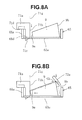
- the operations of the restricting lever 71 and the pressing lever 72 are explained with reference to FIGS. 8A to 9B . As described above, the restricting lever 71 and the pressing lever 72 move downward under their own weights in a manner to follow rotation of the separator 69.
- the first-side end portion 9a of the winding tube 9 is placed toward an inner side of the winding-tube tray 65 relative to a position 71g where the first-side end portion 9a is restricted by the restricting lever 71.
- the restricting plate 71a of the restricting lever 71 is inserted into the opening 65b in the winding-tube tray 65 from above to be positioned by resting on the side wall portion 65a first.
- the restricting plate 71a has a shape of an inverted L.
- the restricting plate 71a includes a vertical portion 71b that extends in a direction perpendicular to a winding-tube carrying surface 65e of the winding-tube tray 65.
- the vertical portion 71b is arranged on the restriction position 71g of the first-side end portion 9a of the winding tube 9.
- the restricting plate 71a also includes a parallel portion 71d that extends in a horizontal direction corresponding to the winding-tube carrying surface 65e of the winding-tube tray 65.
- the parallel portion 71d rests on the side wall portion 65a of the winding-tube tray 65.
- the pressing plate (pressing member) 72a of the pressing lever 72 presses the second-side end portion 9b of the winding tube 9 against the restricting plate 71a from above.
- the pressing plate 72a is inclined to the horizontal direction corresponding the winding-tube carrying surface 65e.
- the pressing plate 72a moves downward to come in contact with the second-side end portion 9b of the winding tube 9 and presses the winding tube 9 against the restricting plate 71a of the restricting lever 71 by a component Gh of a force of gravity acting on the pressing lever 72.
- the first-side end portion 9a of the winding tube 9 is restricted by the vertical portion 71b of the restricting plate 71a, while the second-side end portion 9b of the winding tube 9 is pressed by the pressing plate 72a. As a result, the winding tube 9 is positioned to the specified position.
- the first-side end portion 9a of the winding tube 9 is placed toward an outer side of the winding-tube tray 65 relative to the position 71g where the first-side end portion 9a is restricted by the restricting lever 71.
- the restricting plate 71a of the restricting lever 71 includes an inclined portion 71c that is inclined to the horizontal direction corresponding the winding-tube carrying surface 65e. Moving down the restricting plate 71a brings the inclined portion 71c into contact with the first-side end portion 9a of the winding tube 9 first. Thereafter, as shown in FIG. 9B , the restricting plate 71a presses the winding tube 9 under the weight of the restricting lever 71, causing the first-side end portion 9a of the winding tube 9 to slide along the inclined portion 71c to come into contact with the vertical portion 71b.
- the vertical portion 71b of the restricting plate 71a is placed at a position where the vertical portion 71b reliably abuts on the first-side end portion 9a of the winding tube 9 because the inclined portion 71c of the restricting plate 71a passes through the opening 65b in the winding-tube tray 65.
- the pressing plate 72a of the pressing lever 72 presses the second-side end portion 9b of the winding tube 9 against the restricting plate 71a.
- the first-side end portion 9a of the winding tube 9 is restricted by the vertical portion 71b of the restricting plate 71a, and the second-side end portion 9b of the winding tube 9 is pressed by the pressing plate 72a, causing the winding tube 9 to be positioned to the specified position.
- the restricting lever 71 and the pressing lever 72 are provided in the doffing apparatus 6. Accordingly, the positions of the restricting plate 71a of the restricting lever 71 and the pressing plate 72a of the pressing lever 72 can be adjusted according to a stop position of the doffing apparatus 6. Therefore, the winding tube 9 can be positioned to the specified position according to the stop position of the doffing apparatus 6. Put another way, the winding tube 9 can be positioned to a proper mounting position in the cradle arms 21, independent of a position where the winding-tube tray 65 is installed, by controlling the stop position of the doffing apparatus 6. Hence, improper mounting is prevented.
- the pressing plate 72a of the pressing lever 72 presses the second-side end portion 9b of the winding tube 9 against the restricting plate 71a of the restricting lever 71. Accordingly, the winding tube 9 is accurately positioned to the specified position even when the winding tubes 9 to be used have various lengths.
- the pressing lever 72 rotates about the second support shaft 73 under its own weight. Accordingly, a force acting on the winding tube 9 does not exceed a force due to the weight of the pressing lever 72, and application of an excessively large force on the second-side end portion 9b of the winding tube 9 does not occur. Furthermore, the restricting lever 71 and the pressing lever 72 move in a manner to follow the separator 69 and therefore have a simple structure that does not require a driving mechanism. Note that the restricting lever 71 and the pressing lever 72 can alternatively be driven by a driving mechanism (an air cylinder, a motor, or the like).
- a driving mechanism an air cylinder, a motor, or the like.
- the yarn cutting section 27a of the yarn clearer 27 is actuated to cut the yarn Y, and simultaneously the suction arm 28 sucks and catches a leading end of the cut yarn Y coming from the yarn supplying bobbin B. Simultaneously with this operation of the winding device 2, the doffing apparatus 6 travels and stops at a position immediately above the fully-wound winding package P of the winding device 2.
- the unit controller 24 drives the drive motor 25 to thereby rotate the drum 22 at a low speed, causing the cut yarn Y coming from the winding package P to be wound onto the winding package P.
- the unit controller 24 stops driving of the drive motor 25 to stop rotation of the drum 22.
- the doffing apparatus 6 After the cut yarn Y has been wound onto the winding package P, the doffing apparatus 6 causes the opener 63 to swivel to thereby move the cradle arms 21 that hold the fully-wound package P from the winding position to the dismounting position. Furthermore, the doffing apparatus 6 opens the cradle arms 21 by causing the opener 63 to rock in the axial direction of the drum 22, thereby removing the fully-wound package P (perform doffing). The fully-wound package P is placed on the transporting device 12 via a package guide 29 and conveyed to a predetermined location.
- the opener 63 stops rocking and swivels toward the drum 22 to move the cradle arms 21 to the winding position.
- the opener 63 is then caused to rock again to open the cradle arms 21.
- the yarn clamping device 62 of the doffing apparatus 6 extends to the suction arm 28 to cut and grip the leading end of the yarn Y, which is coming from the yarn supplying bobbin B and sucked and caught by the suction arm 28, and then ascends to pull up the yarn Y to a position above the drum 22 across in front of the drum 22.
- the yarn clamping device 62 that has pulled up the yarn Y to the position above the drum 22 swivels toward the cradle arms 21, thereby interposing the yarn Y between the cradle arms 21 and also inserts the yarn Y into the yarn clearer 27 to detect presence/absence of the yarn Y.
- the yarn handling lever 64 of the doffing apparatus 6 pivots toward the drum 22 to hook the yarn Y, which is on the side from which the yarn Y is introduced to the drum 22, on a leading end of the yarn handling lever 64 and guides the yarn Y to a bunch winding position.
- the chuck 66 pivots toward the drum 22 to hold the winding tube 9 at an unloading opening end (front end) of the winding-tube tray 65.
- the separator 69 pivots downward about the first support shaft 69c in conjunction with the chuck 66, and causes the remainder of the winding tubes 9 to retreat upward before the chuck 66 holds the to-be-held winding tube 9. Meanwhile, this retreat is maintained until the chuck 66 mounts the winding tube 9 held by the chuck 66 into the cradle arms 21 and returns to its default position.
- the restricting plate 71a of the restricting lever 71 restricts the position of the first-side end portion 9a of the to-be-held winding tube 9, and the pressing plate 72a of the pressing lever 72 presses the second-side end portion 9b of the to-be-held winding tube 9 against the restricting plate 71a.
- the to-be-held winding tube 9 is positioned to the specified position.
- the chuck 66 holds the winding tube 9, and thereafter further pivots toward the drum 22, thereby bringing the winding tube 9 held by the chuck 66 into contact with the drum 22 and placing the winding tube 9 between the winding-tube holders 23 of the cradle arms 21.
- Rocking motion of the opener 63 is stopped while maintaining contact between the winding tube 9 and the drum 22 so that the winding tube 9 is rotatably held at its large-diameter end and small-diameter end between the winding-tube holders 23 of the cradle arms 21.
- the yarn Y is clamped between the large-diameter end of the winding tube 9 and one of the winding-tube holders 23; hence, a state where bunch winding can be performed onto the winding tube 9 is achieved.
- the chuck 66 pivots and retreats toward the doffing apparatus 6, and simultaneously, the yarn Y clamped by the yarn clamping device 62 is released.
- the unit controller 24 causes the drive motor 25 to drive to rotate the drum 22 at a low speed, thereby performing bunch winding of the yarn Y coming from the yarn supplying bobbin B onto the large-diameter end of the winding tube.
- the unit controller 24 then controls the drive motor 25 to cause the drum 22 to rotate continuously while transferring from low-speed rotation to high-speed rotation to automatically start production winding of the yarn Y.
- production winding during which the drum 22 rotates the winding tube 9 at a high speed while causing the yarn Y to be traversed in the axial direction of the winding tube 9, of the yarn Y is automatically started.
- the production winding of the yarn Y ends at completion of winding of a predetermined length, or when the number of rotations of the drum 22 counted by the unit controller 24 reaches the number of full-winding rotations.
- the doffing apparatus 6 performs doffing of the fully-wound package P on the winding device 2 that has fully wound the yarn Y.
- the doffing apparatus is applied to the automatic winder including a plurality of winding devices arranged side-by-side; however, application of the doffing apparatus is not limited thereto.
- the doffing apparatus can be applied to a spinning machine including a plurality of spinning devices arranged side-by-side.
- a doffing apparatus that travels to a desired one among a plurality of winding units arranged side-by-side, each of the winding units including a winding-tube tray and a winding-tube supporting member, and supplies a winding tube to the winding unit from the winding-tube tray includes a chuck that holds the winding tube and supplies the winding tube to the winding-tube supporting member of the winding unit; a restricting lever that comes into contact with a first-side end portion of the winding tube held by the chuck thereby restricting a position of the first-side end portion of the winding tube; and a pressing lever that comes into contact with a second-side end portion, which is on an opposite side of the winding tube from the first-side end portion, of the winding tube restricted by the restricting lever and presses the second-side end portion of the winding tube against the restricting lever.
- the doffing apparatus positions the winding tube held by the chuck using the restricting lever
- the restricting lever includes a vertical portion for restricting the position of the first-side end portion of the winding tube and an inclined portion for causing the first-side end portion of the winding tube to slide
- the pressing lever includes a pressing member that comes into contact with the second-side end portion of the winding tube and presses the winding tube against the restricting lever.
- the vertical portion extends in a direction perpendicular to a winding-tube carrying surface of the winding-tube tray.
- the inclined portion being inclined to a horizontal direction corresponding the winding-tube carrying surface of the winding-tube tray.
- the pressing member being inclined to the horizontal direction corresponding the winding-tube carrying surface.
- the doffing apparatus further includes a separator that, when the chuck holds the winding tube, causes a remainder of the winding tubes to retreat.
- the remainder is the winding tubes other than the winding tube to be held by the chuck.
- the doffing apparatus further includes a first support shaft and a second support shaft, the separator is rotatably supported on the first support shaft, the restricting lever and the pressing lever are rotatably supported on the second support shaft and rest on the separator, and when the separator rotates about the first support shaft downward, the restricting lever and the pressing lever rotate downward under a weight of the restricting lever and a weight of the pressing lever, respectively, about the second support shaft in a manner to follow the separator.
- the doffing apparatus includes the restricting lever that restricts the position of the first-side end portion of the winding tube and the pressing lever that presses the second-side end portion of the winding tube restricted by the restricting lever against the restricting lever. Accordingly, the winding tube held by the chuck is positioned by the restricting lever and the pressing lever.
- the positions of the restricting lever and the pressing lever can be adjusted according to a stop position of the doffing apparatus because the restricting lever and the pressing lever are installed on the doffing apparatus. Therefore, it is possible to restrict the winding tube to a specified position according to the stop position of the doffing apparatus.
- the winding tube can be positioned to a proper mounting position in the cradle arms independent of a position where the winding-tube tray is installed. It is possible to accurately position the winding tube even when the winding tube to be used varies in length because the pressing lever presses the winding to against the restricting lever.
- a textile machine includes the above doffing apparatus and a plurality of winding units.
Landscapes
- Engineering & Computer Science (AREA)
- Mechanical Engineering (AREA)
- Textile Engineering (AREA)
- Replacing, Conveying, And Pick-Finding For Filamentary Materials (AREA)
- Spinning Or Twisting Of Yarns (AREA)
Applications Claiming Priority (1)
| Application Number | Priority Date | Filing Date | Title |
|---|---|---|---|
| JP2011204704A JP2013063841A (ja) | 2011-09-20 | 2011-09-20 | 玉揚装置及びそれを備えた繊維機械 |
Publications (2)
| Publication Number | Publication Date |
|---|---|
| EP2573233A2 true EP2573233A2 (fr) | 2013-03-27 |
| EP2573233A3 EP2573233A3 (fr) | 2016-11-16 |
Family
ID=46758668
Family Applications (1)
| Application Number | Title | Priority Date | Filing Date |
|---|---|---|---|
| EP12182980.8A Withdrawn EP2573233A3 (fr) | 2011-09-20 | 2012-09-04 | Machine de dégarnissage et machine textile |
Country Status (3)
| Country | Link |
|---|---|
| EP (1) | EP2573233A3 (fr) |
| JP (1) | JP2013063841A (fr) |
| CN (1) | CN103010844B (fr) |
Cited By (7)
| Publication number | Priority date | Publication date | Assignee | Title |
|---|---|---|---|---|
| EP3006384A1 (fr) * | 2014-10-08 | 2016-04-13 | Murata Machinery, Ltd. | Dispositif de séparation de bobine, chariot déchargeur et machine de bobinage de fil |
| CN105540344A (zh) * | 2016-01-29 | 2016-05-04 | 湖州南浔金吉宝纺织有限公司 | 纱线自动复绕装置 |
| EP3312116A1 (fr) * | 2016-10-19 | 2018-04-25 | Murata Machinery, Ltd. | Dispositif de bobinage de fil et procédé d'arrêt de rotation de paquet |
| WO2019008421A1 (fr) * | 2017-07-05 | 2019-01-10 | Patel Brij | Système de levée automatique pour machines d'étirage-texturation et machines de texturation par air |
| WO2020130962A1 (fr) * | 2018-12-21 | 2020-06-25 | Durak Teksti̇l Sanayi̇ Ve Ti̇caret Anoni̇m Şi̇rketi̇ | Bobinoir pour fils sans mandrin |
| DE102015205181B4 (de) | 2014-03-25 | 2022-09-29 | Murata Machinery, Ltd. | Spulenlagereinrichtung und Garnwickelmaschine |
| DE102024105812A1 (de) * | 2024-02-29 | 2025-09-04 | Rieter Ag | Hülsenmagazin für Spulhülsen, Verfahren zum Handhaben von Spulhülsen, Arbeitsstelle einer kreuzspulenherstellenden Textilmaschine sowie kreuzspulenherstellende Textilmaschine |
Families Citing this family (3)
| Publication number | Priority date | Publication date | Assignee | Title |
|---|---|---|---|---|
| CN103526364B (zh) * | 2013-10-18 | 2015-10-07 | 陕西华燕航空仪表有限公司 | 落筒机械手 |
| CN111017649B (zh) * | 2018-10-09 | 2023-04-11 | 欧瑞康纺织有限及两合公司 | 纺织机械的卷绕设备 |
| CN112093583B (zh) * | 2020-09-24 | 2022-09-20 | 陕西华燕航空仪表有限公司 | 一种纺纱筒管定位装置 |
Citations (1)
| Publication number | Priority date | Publication date | Assignee | Title |
|---|---|---|---|---|
| JP2008162712A (ja) | 2006-12-27 | 2008-07-17 | Murata Mach Ltd | 玉揚装置およびそれを備えた繊維機械 |
Family Cites Families (7)
| Publication number | Priority date | Publication date | Assignee | Title |
|---|---|---|---|---|
| CS268434B1 (en) * | 1987-12-02 | 1990-03-14 | Milan Ing Eckhardt | Device for cones' doffing with textile machine |
| CZ283034B6 (cs) * | 1994-08-24 | 1997-12-17 | Maschinenfabrik Rieter Ag | Způsob a zařízení k zásobování navíjecích ústrojí textilního stroje prázdnými dutinkami |
| DE19910764B4 (de) * | 1999-03-11 | 2011-11-10 | Rieter Ingolstadt Gmbh | Verfahren und Vorrichtung zur Handhabung einer Leerhülse auf einer Textilmaschine |
| JP4487942B2 (ja) * | 2005-05-10 | 2010-06-23 | 村田機械株式会社 | 自動ワインダーの玉揚げ装置 |
| DE102006010855A1 (de) * | 2006-03-09 | 2007-09-13 | Saurer Gmbh & Co. Kg | Vorrichtung zur Spulenabnahme |
| JP2007308814A (ja) * | 2006-05-16 | 2007-11-29 | Murata Mach Ltd | 玉揚げ装置を有する繊維機械 |
| JP2011162351A (ja) * | 2010-01-15 | 2011-08-25 | Murata Machinery Ltd | 玉揚げ装置 |
-
2011
- 2011-09-20 JP JP2011204704A patent/JP2013063841A/ja not_active Withdrawn
-
2012
- 2012-07-11 CN CN201210245419.4A patent/CN103010844B/zh active Active
- 2012-09-04 EP EP12182980.8A patent/EP2573233A3/fr not_active Withdrawn
Patent Citations (1)
| Publication number | Priority date | Publication date | Assignee | Title |
|---|---|---|---|---|
| JP2008162712A (ja) | 2006-12-27 | 2008-07-17 | Murata Mach Ltd | 玉揚装置およびそれを備えた繊維機械 |
Cited By (8)
| Publication number | Priority date | Publication date | Assignee | Title |
|---|---|---|---|---|
| DE102015205181B4 (de) | 2014-03-25 | 2022-09-29 | Murata Machinery, Ltd. | Spulenlagereinrichtung und Garnwickelmaschine |
| EP3006384A1 (fr) * | 2014-10-08 | 2016-04-13 | Murata Machinery, Ltd. | Dispositif de séparation de bobine, chariot déchargeur et machine de bobinage de fil |
| CN105540344A (zh) * | 2016-01-29 | 2016-05-04 | 湖州南浔金吉宝纺织有限公司 | 纱线自动复绕装置 |
| CN105540344B (zh) * | 2016-01-29 | 2018-05-18 | 湖州南浔金吉宝纺织有限公司 | 纱线自动复绕装置 |
| EP3312116A1 (fr) * | 2016-10-19 | 2018-04-25 | Murata Machinery, Ltd. | Dispositif de bobinage de fil et procédé d'arrêt de rotation de paquet |
| WO2019008421A1 (fr) * | 2017-07-05 | 2019-01-10 | Patel Brij | Système de levée automatique pour machines d'étirage-texturation et machines de texturation par air |
| WO2020130962A1 (fr) * | 2018-12-21 | 2020-06-25 | Durak Teksti̇l Sanayi̇ Ve Ti̇caret Anoni̇m Şi̇rketi̇ | Bobinoir pour fils sans mandrin |
| DE102024105812A1 (de) * | 2024-02-29 | 2025-09-04 | Rieter Ag | Hülsenmagazin für Spulhülsen, Verfahren zum Handhaben von Spulhülsen, Arbeitsstelle einer kreuzspulenherstellenden Textilmaschine sowie kreuzspulenherstellende Textilmaschine |
Also Published As
| Publication number | Publication date |
|---|---|
| EP2573233A3 (fr) | 2016-11-16 |
| CN103010844B (zh) | 2016-09-28 |
| CN103010844A (zh) | 2013-04-03 |
| JP2013063841A (ja) | 2013-04-11 |
Similar Documents
| Publication | Publication Date | Title |
|---|---|---|
| EP2573233A2 (fr) | Machine de dégarnissage et machine textile | |
| JP2730585B2 (ja) | 紡績運転を迅速に再開する方法と装置 | |
| US3295775A (en) | Method and apparatus for readying the winding operation of yarn supply coils on coil winding machines | |
| JP2011162351A (ja) | 玉揚げ装置 | |
| JP2792879B2 (ja) | 紡績運転再開のための方法 | |
| EP2441718B1 (fr) | Appareil renvideur de fil | |
| JP2015147633A (ja) | ボビンセット装置、及び糸巻取機 | |
| JP2014043348A (ja) | 巻取り機の作業部において上糸と下糸とを糸継ぎする方法並びに巻取り機の作業部 | |
| KR920002549B1 (ko) | 자동 와인더로의 관사 반송공급장치 | |
| CN101184685B (zh) | 具有位于卷绕机构下方的、用于空纱管的纡库的卷绕站 | |
| JPH08209466A (ja) | 綾巻きボビンを製造する繊維機械 | |
| US20010022071A1 (en) | Device for starting a work station of a cheese-producing textile machine | |
| JP2006089284A (ja) | 自動綾巻きワインダの作業部に用いられる挿嵌心棒 | |
| JP2002326767A (ja) | 自動ワインダにおける巻取管への糸装着方法及び自動ワインダ | |
| JP2012086925A (ja) | ボビンセット装置及びそれを備える糸巻取機 | |
| JP5832322B2 (ja) | 自動綾巻きワインダの作業部 | |
| CN107963512B (zh) | 纱线卷取装置以及卷装的旋转停止方法 | |
| EP3006384B1 (fr) | Dispositif de séparation de bobine, chariot déchargeur et machine de bobinage de fil | |
| US5343687A (en) | Winder-to-double twister connecting system | |
| JP2008162712A (ja) | 玉揚装置およびそれを備えた繊維機械 | |
| JP2023142771A (ja) | 糸巻取機及び糸巻取方法 | |
| JP2013056766A (ja) | 玉揚装置、及びこれを備える繊維機械 | |
| JP2009084023A (ja) | 繊維機械 | |
| JP3707413B2 (ja) | 糸太さ検出器を備える糸条巻取機 | |
| JP6605256B2 (ja) | 綾巻きパッケージを製造する繊維機械の作業ユニット |
Legal Events
| Date | Code | Title | Description |
|---|---|---|---|
| PUAI | Public reference made under article 153(3) epc to a published international application that has entered the european phase |
Free format text: ORIGINAL CODE: 0009012 |
|
| AK | Designated contracting states |
Kind code of ref document: A2 Designated state(s): AL AT BE BG CH CY CZ DE DK EE ES FI FR GB GR HR HU IE IS IT LI LT LU LV MC MK MT NL NO PL PT RO RS SE SI SK SM TR |
|
| AX | Request for extension of the european patent |
Extension state: BA ME |
|
| PUAL | Search report despatched |
Free format text: ORIGINAL CODE: 0009013 |
|
| AK | Designated contracting states |
Kind code of ref document: A3 Designated state(s): AL AT BE BG CH CY CZ DE DK EE ES FI FR GB GR HR HU IE IS IT LI LT LU LV MC MK MT NL NO PL PT RO RS SE SI SK SM TR |
|
| AX | Request for extension of the european patent |
Extension state: BA ME |
|
| RIC1 | Information provided on ipc code assigned before grant |
Ipc: D01H 9/02 20060101AFI20161010BHEP Ipc: B65H 67/06 20060101ALI20161010BHEP |
|
| STAA | Information on the status of an ep patent application or granted ep patent |
Free format text: STATUS: THE APPLICATION HAS BEEN WITHDRAWN |
|
| 18W | Application withdrawn |
Effective date: 20170428 |