EP2573254A1 - Nadelrichtanordnung zur Verzugskorrektur einer geförderten Warenbahn sowie ein zugehöriges Verfahren - Google Patents
Nadelrichtanordnung zur Verzugskorrektur einer geförderten Warenbahn sowie ein zugehöriges Verfahren Download PDFInfo
- Publication number
- EP2573254A1 EP2573254A1 EP12182724A EP12182724A EP2573254A1 EP 2573254 A1 EP2573254 A1 EP 2573254A1 EP 12182724 A EP12182724 A EP 12182724A EP 12182724 A EP12182724 A EP 12182724A EP 2573254 A1 EP2573254 A1 EP 2573254A1
- Authority
- EP
- European Patent Office
- Prior art keywords
- web
- abnadelstelle
- needle
- pivot axis
- straightening
- Prior art date
- Legal status (The legal status is an assumption and is not a legal conclusion. Google has not performed a legal analysis and makes no representation as to the accuracy of the status listed.)
- Granted
Links
Images


Classifications
-
- D—TEXTILES; PAPER
- D06—TREATMENT OF TEXTILES OR THE LIKE; LAUNDERING; FLEXIBLE MATERIALS NOT OTHERWISE PROVIDED FOR
- D06H—MARKING, INSPECTING, SEAMING OR SEVERING TEXTILE MATERIALS
- D06H3/00—Inspecting textile materials
- D06H3/12—Detecting or automatically correcting errors in the position of weft threads in woven fabrics
Definitions
- the invention relates to a Nadelrichtan Aunt for distortion correction of a conveyed web according to the preamble of claim 1 and an associated method according to the preamble of claim 8.
- a textile material web consists in particular of threads crossed at right angles, which are produced during the weaving process in the loom or in the weaving machine.
- warp longitudinal threads
- weft transverse threads
- skew direction of goods warp
- bow distortion arcuate to the direction of goods running distortion
- the textile web is guided over mechanical straightening arrangements, in which the existing distortions are compensated for by means of corresponding application of compensating forces on the moving textile material web by means of roll units arranged obliquely or arcuately to the running direction of the textile web.
- roll units arranged obliquely or arcuately to the running direction of the textile web.
- needle straightening arrangements are known in which the moving textile web is tensioned at the opposite web edges over at least two oppositely arranged needle straightening wheels transversely to the running direction of the textile web.
- the directional wheels By pivoting the directional wheels about a pivot axis in one given angle to the direction of the textile web and with a predetermined lateral force each side acting outward transverse stress is introduced into the textile web and thereby causes a spreading of the web.
- the web edges of the warped textile web are thus subjected to a defined straightening force to the outside, ie in the direction of the weft of the textile web.
- the result is a component of force that seeks to re-shape the parallelogram structure into the original orthogonal structure.
- the width of the web when needling special importance, which usually falls below the width of the web in the unloaded state due to the machine promotion of the web.
- the needling of the web takes place regardless of their web properties always the same, so that some high residual distortions are introduced into the web, which lead to increased mechanical complexity in the post-correction.
- the present invention seeks to provide a Nadelrichtan instructs to provide a Nadelrichtan instructs to provide a Nadelrichtan instructs to provide a Nadelrichtan instructs to provide a Nadelrichtan instructs to provide a Nadelrichtan instructs to provide a Nadelrichtan instructs to provide a Nadelrichtan instructs to provide a Nadelrichtan instructs to provide a Nadelrichtan instructing the Abnadelstelle a Nadelrichtan inch, which has an improved directivity compared to known Nadelrichtan empen.
- the object is achieved on the basis of a Nadelrichtan instructs to provide a Nadelrichtan instructs to provide a Nadelrichtan instructs to provide.
- the essential aspect of the device according to the invention is to be seen in that the needle roller is pivotally formed about a pivot axis.
- Abnadelstelle adjustable by pivoting the Abnadelwalze to the first and second pivot point of the needle-directional receiving pivot axis.
- the needle straightening wheels are designed to produce a spreading profile with a first and second spreading profile area, the first and second spreading profile area being approximately symmetrical to one another.
- the Abnadelstelle is adjustable in the second Sp Dahlungsprofil Symposium.
- the maximum spread value of the spreading profile of the straightening wheels is present at that end-side circumferential point of the straightening wheels, at which the distance of the pivot axis opposite the front circumferential point to the respective pivot axis is maximum.
- the spread value decreases from the maximum spread value toward the point of needling.
- the subject matter of the present invention is also a method for adjusting the Abnadelstelle a at least two needle directions having needle straightening arrangement for distortion correction of a subsidized, especially textile web, in which the conveyed web is applied with the opposite edges of the fabric at a Aufnadelstelle on the Nadelrichtiza and at a Abnadelstelle of the Needle direction wheels is removed again.
- the Abnadelstelle means a pivotable Abnadelwalze trajectory adjusted.
- the Abnadelwalze is preferably pivoted along the circumference of Nadelrichtrastn, the Abnadelstelle is adjusted depending on the material properties of the web, in particular their elasticity and / or the strength of the warpage of the web and / or the width of the web at the Aufnadelstelle.
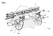
- FIG. 1 is shown in a perspective view of a needle straightening arrangement 1 according to the invention in a simplified representation, which have at least a first Nadelrichtrad 2 and a second Nadelrichtrad 3.
- the Nadelrichtrast 2, 3 each have from the front side in the radial direction outwardly projecting needles, which distributes almost uniformly along the frontal periphery of the needle direction wheels 2 are.
- Such a needle straightening arrangement 1 can either be part of a textile processing machine or a straightening machine 4.
- FIG. 2 For example, a schematic cross-section through a straightening machine 4 is shown, which has a needle straightening arrangement 1 according to the invention.
- the web W is hereby conveyed in a web direction WL through the Nadelrichtan Aunt 1 and thereby subjected to a straightening process.
- the straightening machine 4 comprises, for example, a schematic in FIG FIG. 2 indicated machine frame 5, in which the Nadelrichtan Aunt invention 1 and further roller assemblies are added.
- the machine frame 5 forms a rigid, rectangular frame, through which the web W can be conveyed through and thereby can be subjected to several processing steps.
- the basic technical structure of such straightening machines 4 and in particular of the machine frame 5 provided for this purpose is sufficiently known from the prior art and can have very different forms of implementation.
- the first needle straightening wheel 2 is rotatable about a first pivot point DP1 and pivotable about a first pivot axis SA1 and the second needle direction wheel 3 rotatable about a second pivot point DP2 and pivotable about a second pivot axis SA2 formed.
- FIG. 1 shows the Nadelrichtrast 2, 3 in the directional position, ie, the first and second Nadelrichtrad 2, 3 include approximately an acute angle with the fabric direction WL.
- SA1 For pivoting the first and second Nadelrichtrades 2, 3 about the respective pivot axis SA1, SA2 an unspecified adjusting mechanism 6 is provided, via which both the adjustment of the Nadelrichtcken 2, 3 and an adjustment of the distance of the Nadelrichtrate 2, 3 to each present width B of the web W can be adjusted.
- the web W is fed via an inlet roller 7 a roller mill 8, which, for example, an S-wrap can have.
- a spreader roll arrangement 9 for wrinkle-free feeding of the material web W to the straightening arrangement 1 or its directional wheels 2, 3.
- the material web W is fed to a sheet straightening roller arrangement 10 arranged on the output side, by means of which minimal sheet rest distortions still contained in the material web W can be corrected before the material web W leaves the straightening machine 4.
- FIG. 3 to illustrate the operation of the needle straightening arrangement 1 and the straightening wheels 2, 3 is a schematic view of the spread profile SP generated by the Nadelrichtrast 2, 3 shown on the Nadelricht grantn 2,3 needled web W along the fabric direction WL.
- the width B of the web W is selectively increased by the engaging in the opposite web edges W ', W "needles of Nadelrichtrate 2, 3 when passing through a predetermined peripheral region of the straightening wheels 2, 3, ie the web W spread, and then reduced again.
- the spread profile SP thus has a first and second spread profile area SP1, SP2, which run symmetrically to each other.
- the first spread profile area SP1 the spread value S of the material web W increases continuously along the frontal circumference of the directional wheels 2, 3, starting from a minimum spread value S MIN at the point of application N AUF up to a maximum spread value S MAX .
- I'm at it Subsequent second spread profile range SP2 takes the spread value S of the web W along the frontal circumference of the directional wheels 2, 3 from the maximum spread value S MAX up to the minimum spread value S MIN decreases again.
- the maximum spread value S MAX of the directional wheels 2, 3 is in this case at that front circumferential point of the directional wheels 2, 3, at which the distance from the frontal peripheral point to the respective pivot axis SA1, SA2 is maximum, ie the intersection between a two pivot points SP1, SP2 receiving and perpendicular to the pivot axes SA1, SA2 extending plane E and the respective pivot axis SA1, SA2 opposite end face of the directional wheels 2, 3.
- the needle roller 11 is pivotally formed about the first and second pivot point DP1, DP2 of the needle straightening wheels 2, 3 receiving pivot axis SA, in such a way that by pivoting the needle roller 11 about the pivot axis SA the Abnadelstelle N AB along the frontal circumference of the straightening wheels 2, 3 is adjustable.
- the setting of the Abbestadelstelle N AB can be carried out either manually or mechanically by means of a control loop.
- the Abnadelstelle N AB can be adjusted according to the invention in the frontal peripheral region of the Nadelrichtrast 2, 3, preferably in the second Sp Dahlungsprofil Suite SP2 according to the in FIG. 3 shown spreading profile SP, the extends from the front-side circumferential point with the maximum spread value S MAX to the frontal peripheral point with the minimum spread value S MIN .
- the minimum spread value S MIN is approximately at the end face circumferential location opposite the pin point N AUF , at which the respective pivot axis SA 1, SA 2 of the needle straightening wheels 2, 3 intersects the front peripheral area of the needle straightening wheels 2, 3.
Landscapes
- Engineering & Computer Science (AREA)
- Chemical & Material Sciences (AREA)
- Materials Engineering (AREA)
- Textile Engineering (AREA)
- Treatment Of Fiber Materials (AREA)
Abstract
Description
- Die Erfindung betrifft eine Nadelrichtanordnung zur Verzugskorrektur einer geförderten Warenbahn gemäß dem Oberbegriff des Patentanspruches 1 sowie ein zugehöriges Verfahren gemäß dem Oberbegriff des Patentanspruches 8.
- Während des maschinellen Herstellungs- und Verarbeitungsprozesses von geförderten Warenbahnen tritt häufig ein Warenverzug auf. Derartige Verzüge der Warenbahn verändern die Struktur der aus diesen hergestellten Waren wie beispielsweise Textilien oder gewebte Teppiche, wodurch wiederum der Gebrauchswert der Waren gemindert wird und/oder die Weiterverarbeitung der Waren beeinträchtigt wird.
- Eine textile Warenbahn besteht insbesondere aus rechtwinklig überkreuzten Fäden, die während des Webvorgangs im Webstuhl bzw. in der Webmaschine erzeugt werden. Hierbei wird zwischen den Längsfäden ("Kette") und den Querfäden ("Schuss") unterschieden. Aufgrund des überlicherweise schräg zur Warenlaufrichtung verlaufenden Verzugs ("Schrägverzug") oder bogenförmig zur Warenlaufrichtung verlaufenden Verzugs ("Bogenverzug") der textilen Warenbahn wird die orthogonale Textilstruktur von Kette und Schuss verformt. Der ursprünglich orthogonale Aufbau von Kette und Schuss oder deren Maschenreihen werden somit schräg oder bogenförmig verändert, d.h. ein Schräg- und/oder Bogenverzug liegt vor.
- Zur Wiederherstellung der ursprünglich orthogonalen Struktur wird die Textilbahn über maschinelle Richtanordnungen geführt, bei der mittels schräg oder bogenförmig zur Laufrichtung der Textilbahn angeordneten Walzeneinheiten die bestehenden Verzüge durch entsprechendes Aufbringen von Ausgleichskräften auf die bewegte textile Warenbahn ausglichen werden. Derartige walzenbasierte Richtanordnungen werden bevorzugt zur Beseitigung von bogenförmigen Faden- und Maschenverzug eingesetzt.
- Alternativ sind so genannte Nadelrichtanordnungen bekannt, bei denen die bewegte textile Warenbahn an den gegenüberliegenden Warenbahnkanten über zumindest zwei gegenüber angeordnete Nadelrichträder quer zur Laufrichtung der textilen Warenbahn gespannt wird. Durch Schwenken der Richträder um eine Schwenkachse in einen vorgegebenen Winkel zur Laufrichtung der textilen Warenbahn und mit einer vorgegebenen Querkraft wird jeweils eine seitlich nach außen wirkende Querspannung in die textile Warenbahn eingeleitet und dadurch eine Spreizung der Warenbahn bewirkt. Die Warenbahnkanten der verzogenen textilen Warenbahn werden somit mit einer definierten Richtkraft nach außen, d.h. in Richtung des Schusses der Textilbahn beaufschlagt. So entsteht eine Kräftekomponente, die bestrebt ist, die Parallelogrammstruktur in die ursprünglich orthogonale Struktur zurückzuformen.
- Hierbei ergibt sich durch die Schrägstellung der Richträder ausgehend von Aufnadelstelle, in welcher ein minimaler Spreizungswert vorliegt, ein Ansteigen des Spreizungswertes der Warenbahn bis zum einem maximalen Spreizungswert und nach Überschreiten dessen ein Abnehmen des Spreizungswertes der Warenbahn bis zur Abnadelstelle. Da durch die Richträder per se zumindest ein geringfügiger Bogenverzug in die Warenbahn eingebracht wird, ist der Nadelrichtanordnung häufig eine Bogenrichtwalzenanordnung nachgeschaltet.
- Entscheidend für den Umfang der durch die Nadelrichtanordnung eingebrachten Restverzüge, insbesondere Bogenverzüge ist jedoch der Zeitpunkt des Abnehmens bzw. Abnadelns der textilen Warenbahn von den Richträdern. So erhöht sich beispielsweise der durch die Nadelrichtanordnung eingebrachte Bogenverzug bei einem zu späten Abnadeln der Warenbahn von den Richträdern, wohingegen bei einem zu frühen Abnadeln noch so hohe Richtkräfte auf die Warenbahn wirken, dass die Warenbahn nahezu aus den Richträdern gerissen wird, wodurch Kantenverzüge bis hin zur Beschädigung der Warenkanten entstehen können. Der Zeitpunkt der Abnadelung der Warenbahn bzw. die Auswahl der Abnadelstelle von den Richträdern ist insbesondere abhängig von den Materialeigenschaften, insbesondere deren Elastizität und/oder dem Warenbahnzustand, insbesondere der Stärke des vorliegenden Warenverzugs. Auch kommt der Breite der Warenbahn beim Aufnadeln eine besondere Bedeutung zu, welche aufgrund der maschinellen Förderung der Warenbahn üblicherweise die Breite der Warenbahn im unbelasteten Zustand unterschreitet. Bei herkömmlichen Nadelrichtanordnungen erfolgt die Abnadelung der Warenbahn unabhängig von deren Warenbahneigenschaften immer gleich, so dass zum Teil hohe Restverzüge in die Warenbahn eingebracht werden, die zu einem erhöhten maschinellen Aufwand in deren Nachkorrektur führen.
- Ausgehend hiervon liegt der Erfindung die Aufgabe zugrunde, eine Nadelrichtanordnung und ein zugehöriges Verfahren zur Einstellung der Abnadelstelle einer Nadelrichtanordnung anzugeben, welches eine im Vergleich zu bekannten Nadelrichtanordnungen eine verbesserte Richtwirkung aufweist. Die Aufgabe wird ausgehend von einer Nadelrichtanordnung gemäß dem Oberbegriff des Patentanspruches 1 durch dessen kennzeichnende Merkmale gelöst. Die Merkmale des erfindungsgemäßen Verfahrens sind in dem Patentanspruch 8 aufgeführt.
- Der wesentliche Aspekt der erfindungsgemäßen Vorrichtung ist darin zu sehen, dass die Abnadelwalze schwenkbar um eine Schwenkachse ausgebildet ist. Hierdurch ist eine warenbahnindividuelle Einstellung der Abnadelstelle möglich, welche zu einer deutlich verbesserten Verzugskorrektur führt.
- Weiterhin vorteilhaft ist durch Verschwenken der Abnadelwalze um die den ersten und zweiten Drehpunkt der Nadelrichträder aufnehmende Schwenkachse die Abnadelstelle einstellbar.
- Die Nadelrichträder sind zur Erzeugung eines Spreizungsprofils mit einem ersten und zweiten Spreizungsprofilbereich ausgebildet, wobei der erste und zweite Spreizungsprofilbereich näherungsweise symmetrisch zueinander sind. Vorteilhaft ist die Abnadelstelle im zweiten Spreizungsprofilbereich einstellbar.
- Der maximale Spreizungswert des Spreizungsprofils der Richträder liegt an derjenigen stirnseitigen Umfangsstelle der Richträder vor, an der der Abstand der der Schwenkachse gegenüberliegenden stirnseitigen Umfangsstelle zur jeweiligen Schwenkachse maximal ist. Vorzugsweise nimmt im zweiten Spreizungsprofilbereich der Spreizungswert vom maximalen Spreizungswert zur Abnadelstelle hin abnimmt.
- Ebenfalls ist Gegenstand der vorliegenden Erfindung ein Verfahren zur Einstellung der Abnadelstelle einer zumindest zwei Nadelrichträder aufweisenden Nadelrichtanordnung zur Verzugskorrektur einer geförderten, insbesondere textilen Warenbahn, bei dem die geförderte Warenbahn mit den gegenüberliegenden Warenkanten an einer Aufnadelstelle auf die Nadelrichträder aufgebracht wird und an einer Abnadelstelle von den Nadelrichträdern wieder abgenommen wird. Vorteilhaft wird die Abnadelstelle mittels einer schwenkbaren Abnadelwalze warenbahnabhängig eingestellt. Zur Einstellung der Abnadelstelle wird die Abnadelwalze vorzugsweise entlang des Umfangs der Nadelrichträdern verschwenkt, wobei die Abnadelstelle abhängig von den Materialeigenschaften der Warenbahn, insbesondere deren Elastizität und/oder der Stärke des Verzugs der Warenbahn und/oder der Breite der Warenbahn an der Aufnadelstelle eingestellt wird.
- Die Erfindung soll nachfolgend anhand von Ausführungsbeispielen im Zusammenhang mit den Figuren näher erläutert werden. Zudem ergeben sich Weiterbildungen, Vorteile und Anwendungsmöglichkeiten der Erfindung auch aus der nachfolgenden Beschreibung von Ausführungsbeispielen und aus den Figuren. Dabei sind alle beschriebenen und/oder bildlich dargestellten Merkmale für sich oder in beliebiger Kombination grundsätzlich Gegenstand der Erfindung, unabhängig von ihrer Zusammenfassung in den Ansprüchen oder deren Rückbeziehung. Auch wird der Inhalt der Ansprüche zu einem Bestandteil der Beschreibung gemacht.
- Es wird aber ausdrücklich darauf hingewiesen, dass die Erfindung keinesfalls auf die angegebenen Beispiele beschränkt sein soll. Es zeigen
- Fig. 1
- beispielhaft eine perspektivische Ansicht einer erfindungsgemäßen Nadelrichtanordnung,
- Fig. 2
- beispielhaft einen schematischen Querschnitt durch eine Richtmaschine umfassend eine Nadelrichtanordnung gemäß
Figur 1 sowie weitere Walzenanordnungen und - Fig. 3
- beispielhaft eine schematischen Ansicht auf das durch die Nadelrichtanordnung erzeugte Spreizungsprofil der Warenbahn.
- In
Figur 1 ist in einer perspektivischen Ansicht einer erfindungsgemäßen Nadelrichtanordnung 1 in vereinfachter Darstellung gezeigt, welche zumindest ein erstes Nadelrichtrad 2 und ein zweites Nadelrichtrad 3 aufweisen. Die Nadelrichträder 2, 3 weisen jeweils von der Stirnseite in radialer Richtung nach außen abstehende Nadeln auf, die nahezu gleichmäßig entlang des stirnseitigen Umfanges der Nadelrichträder 2 verteilt sind. Eine derartige Nadelrichtanordnung 1 kann entweder Teil einer Textilverarbeitungsmaschine oder einer Richtmaschine 4 sein. - In
Figur 2 ist beispielsweise ein schematischer Querschnitt durch eine Richtmaschine 4 dargestellt, welche eine erfindungsgemäße Nadelrichtanordnung 1 aufweist. Die Warenbahn W wird hierbei in einer Warenlaufrichtung WL durch die Nadelrichtanordnung 1 gefördert und dadurch einem Richtprozess unterzogen. Die Richtmaschine 4 umfasst beispielsweise ein schematisch inFigur 2 angedeutetes Maschinengestell 5, in dem die erfindungsgemäße Nadelrichtanordnung 1 und weitere Walzenanordnungen aufgenommen sind. - Beispielsweise bildet das Maschinengestell 5 ein starres, rechteckförmiges Rahmengestell aus, durch welches die Warenbahn W hindurch gefördert werden kann und dabei mehreren Bearbeitungsschritten unterzogen werden kann. Der prinzipielle technische Aufbau derartiger Richtmaschinen 4 und insbesondere des hierzu vorgesehenen Maschinengestells 5 ist aus dem Stand der Technik hinreichend bekannt und kann unterschiedlichste Realisierungsformen aufweisen.
- Zum Richten von Verzügen einer über die Nadelrichtanordnung 1 geförderten, insbesondere textilen Warenbahn W ist das erste Nadelrichtrad 2 drehbar um einen ersten Drehpunkt DP1 und schwenkbar um eine erste Schwenkachse SA1 und das zweite Nadelrichtrad 3 drehbar um einen zweiten Drehpunkt DP2 und schwenkbar um eine zweite Schwenkachse SA2 ausgebildet.
-
Figur 1 zeigt dabei die Nadelrichträder 2, 3 in Richtstellung, d.h. das erste und zweite Nadelrichtrad 2, 3 schließen näherungsweise einen spitzen Winkel mit der Warenlaufrichtung WL ein. Zum Schwenken des ersten und zweiten Nadelrichtrades 2, 3 um die jeweilige Schwenkachse SA1, SA2 ist eine nicht näher beschriebene Verstellmechanik 6 vorgesehen, über welche sowohl der Verstellwinkel der Nadelrichträder 2, 3 als auch eine Anpassung des Abstandes der Nadelrichträder 2, 3 an die jeweils vorliegende Breite B der Warenbahn W eingestellt werden kann. - Gemäß dem in
Figur 2 dargestellten Ausführungsbeispiel wird die Warenbahn W über eine Einlaufwalze 7 einem Walzenzugwerk 8 zugeführt, welches beispielsweise eine S-Umschlingung aufweisen kann. Dieser folgt eine Breitstreckwalzenanordnung 9 zur faltenfreien Zuführung der Warenbahn W an die Richtanordnung 1 bzw. deren Richträder 2,3. Nach Durchlaufen der Richtanordnung 1 wird die Warenbahn W einer ausgangsseitig angeordneten Bogenrichtwalzenanordnung 10 zugeführt, mittels der noch in der Warenbahn W enthaltene minimale Bogenrestverzüge korrigiert werden können bevor die Warenbahn W die Richtmaschine 4 verlässt. - Die mittels der Breitstreckwalzenanordnung 9 faltenfrei zugeführte Warenbahn W wird mit Ihren gegenüberliegenden Warenkanten W', W" an einer Aufnadelstelle NAUF auf die Nadelrichträder 2, 3 aufgebracht wird und an einer Abnadelstelle NAB mittels einer Abnadelwalze 11 von den Nadelrichträdern 2, 3 wieder abgenommen wird.
- Unter Aufnadelstelle NAUF wird hierbei näherungsweise diejenige stirnseitige Umfangsstelle der Nadelrichträder 2, 3 verstanden, an der die jeweilige Schwenkachse SA1, SA2 der Nadelrichträder 2, 3 näherungsweise die Stirnseite der Nadelrichträder 2, 3 schneidet. Die geförderte Warenbahn W wird dort derart zugeführt, dass diese an der Aufnadelstelle NAUF von den Nadeln des jeweiligen Nadelrichtrades 2, 3 erfasst wird und anschließend den angestellten Richträdern 2, 3 folgt, wodurch eine Spreizung der Warenbahn W nach außen erzeugt wird.
- In
Figur 3 ist zur Erläuterung der Wirkungsweise der Nadelrichtanordnung 1 bzw. der Richträder 2, 3 eine schematische Ansicht des durch die Nadelrichträder 2, 3 erzeugten Spreizungsprofils SP der auf den Nadelrichträdern 2,3 aufgenadelten Warenbahn W entlang der Warenlaufrichtung WL dargestellt. Hierbei wird die Breite B der Warenbahn W durch die in die gegenüberliegenden Warenbahnkanten W', W" eingreifenden Nadeln der Nadelrichträder 2, 3 bei Durchlaufen eines vorgegebenen Umfangsbereiches der Richträder 2, 3 gezielt vergrößert, d.h. die Warenbahn W gespreizt, und anschließend wieder verkleinert. - Das Spreizungsprofil SP weist somit einen ersten und zweiten Spreizungsprofilbereich SP1, SP2 auf, die symmetrisch zueinander verlaufen. Im ersten Spreizungsprofilbereich SP1 steigt die Spreizungwert S der Warenbahn W entlang des stirnseitigen Umfangs der Richträder 2, 3 ausgehend von einem minimalen Spreizungswert SMIN an der Aufnadelstelle NAUF bis zu einer maximalen Spreizungswert SMAX kontinuierlich an. Im daran anschließenden zweiten Spreizungsprofilbereich SP2 nimmt der Spreizungswert S der Warenbahn W entlang des stirnseitigen Umfangs der Richträder 2, 3 vom maximalen Spreizungswert SMAX bis hin zum minimalen Spreizungswert SMIN wieder abnimmt.
- Der maximale Spreizungswert SMAX der Richträder 2, 3 liegt hierbei an derjenigen stirnseitigen Umfangsstelle der Richträder 2, 3 vor, an der der Abstand von der stirnseitigen Umfangsstelle zur jeweiligen Schwenkachse SA1, SA2 maximal ist, d.h. der Schnittpunkt zwischen einer beide Schwenkpunkte SP1, SP2 aufnehmenden und senkrecht zu den Schwenkachsen SA1, SA2 verlaufenden Ebene E und dem der jeweiligen Schwenkachse SA1, SA2 gegenüberliegenden Stirnseite der Richträder 2, 3. Dadurch ergibt sich der in
Figur 3 dargestellte zum maximalen Spreizungswert SMAX symmetrische Verlauf des Spreizungsprofils SP. - Erfindungsgemäß ist zum Abnehmen der Warenbahn W von den Richträdern 2, 3 die Abnadelwalze 11 schwenkbar um eine den ersten und zweiten Drehpunkt DP1, DP2 der Nadelrichträder 2, 3 aufnehmende Schwenkachse SA ausgebildet, und zwar derart, dass durch Verschwenken der Abnadelwalze 11 um die Schwenkachse SA die Abnadelstelle NAB entlang des stirnseitigen Umfangs der Richträdern 2, 3 einstellbar ist. Dadurch kann besonders vorteilhaft abhängig von den Eigenschaften der zu verarbeitenden Warenbahn W - wie beispielsweise deren Elastizität und/oder die Stärke des vorliegenden Warenverzugs - die Abnadelstelle NAB der Nadelrichtanordnung 1 individuell eingestellt werden, um dadurch ein deutlich verbessertes Richtergebnis zu erhalten. Die Einstellung der Abnadelstelle NAB kann entweder manuell oder maschinell mit Hilfe eines Regelkreises durchgeführt werden.
- Unter Abnadelstelle NAB wird erfindungsgemäß diejenige stirnseitige Umfangsstelle der Nadelrichträder 2, 3 verstanden, an der mittels der Abnadelwalze 11 die Warenbahn W von den Nadeln des jeweiligen Nadelrichtrades 2, 3 gelöst wird und somit die von den Nadelrichträder 2, 3 an der jeweiligen stirnseitigen Umfangsstelle erzeugte Spreizwirkung aufgehoben wird.
- Die Abnadelstelle NAB kann erfindungsgemäß im stirnseitigen Umfangsbereich der Nadelrichträder 2, 3 verstellt werden, und zwar vorzugsweise im zweiten Spreizungsprofilbereich SP2 gemäß dem in
Figur 3 dargestellten Spreizungsprofil SP, der sich von der stirnseitigen Umfangsstelle mit dem maximalen Spreizungswert SMAX bis zur stirnseitigen Umfangsstelle mit dem minimalen Spreizungswert SMIN erstreckt. Der minimalen Spreizungswert SMIN liegt näherungsweise an der dem der Aufnadelstelle NAUF gegenüberliegenden stirnseitigen Umfangsstelle vor, an der die jeweilige Schwenkachse SA1, SA2 der Nadelrichträder 2, 3 den stirnseitigen Umfangsbereich der Nadelrichträder 2, 3 schneidet. - Die Erfindung wurde voranstehend an einem Ausführungsbeispiel beschrieben. Es versteht sich, dass zahlreiche Modifikationen und Änderungen der Erfindung möglich sind, ohne dass hierdurch der Erfindungsgedanke verlassen wird.
-
- 1
- Nadelrichtanordnung
- 2
- erstes Nadelrichtrad
- 3
- zweites Nadelrichtrad
- 4
- Richtmaschine
- 5
- Maschinengestell
- 6
- Verstellmechanik
- 7
- Einlaufwalze
- 8
- Walzenzugwerk
- 9
- Breitstreckwalzenanordnung
- 10
- Bogenrichtwalzenanordnung
- 11
- Abnadelwalze
- B
- Warenbahnbreite
- DP1
- erster Drehpunkt
- DP2
- zweiter Drehpunkt
- E
- Ebene
- NAB
- Abnadelstelle
- NAUF
- Aufnadelstelle
- S
- Spreizungswert
- SA
- Schwenkachse
- SA
- Schwenkachse
- SA1
- erste Schwenkachse
- SA2
- zweite Schwenkachse
- SMAX
- maximaler Spreizungswert
- SMIN
- minimaler Spreizungswert
- SP
- Spreizungsprofil
- SP1
- erster Spreizungsprofilbereich
- SP2
- zweiter Spreizungsprofilbereich
- W
- Warenbahn
- W', W"
- Warenbahnkanten
- WL
- Warenlaufrichtung
Claims (9)
Applications Claiming Priority (1)
| Application Number | Priority Date | Filing Date | Title |
|---|---|---|---|
| DE102011113665.0A DE102011113665B4 (de) | 2011-09-20 | 2011-09-20 | Nadelrichtanordnung zur Verzugskorrektur einer geförderten Warenbahn sowie ein zugehöriges Verfahren |
Publications (2)
| Publication Number | Publication Date |
|---|---|
| EP2573254A1 true EP2573254A1 (de) | 2013-03-27 |
| EP2573254B1 EP2573254B1 (de) | 2014-08-13 |
Family
ID=46762942
Family Applications (1)
| Application Number | Title | Priority Date | Filing Date |
|---|---|---|---|
| EP20120182724 Active EP2573254B1 (de) | 2011-09-20 | 2012-09-03 | Nadelrichtanordnung zur Verzugskorrektur einer geförderten Warenbahn sowie ein zugehöriges Verfahren |
Country Status (2)
| Country | Link |
|---|---|
| EP (1) | EP2573254B1 (de) |
| DE (1) | DE102011113665B4 (de) |
Cited By (1)
| Publication number | Priority date | Publication date | Assignee | Title |
|---|---|---|---|---|
| EP4524310A1 (de) | 2023-09-15 | 2025-03-19 | Corino Macchine S.p.A. | Mit einer vorrichtung zum positionieren eines stofflösezylinders für textilmaschinen ausgestattete richtvorrichtung |
Families Citing this family (1)
| Publication number | Priority date | Publication date | Assignee | Title |
|---|---|---|---|---|
| CN111826925A (zh) * | 2020-08-24 | 2020-10-27 | 常州宏大智能装备产业发展研究院有限公司 | 一种织物整纬或整纬整花机构及方法 |
Citations (5)
| Publication number | Priority date | Publication date | Assignee | Title |
|---|---|---|---|---|
| US4494740A (en) * | 1982-06-19 | 1985-01-22 | Kawakami Co., Ltd. | Spreading equipment having selvage engaging independently rotated needle wheels |
| JPH11222767A (ja) * | 1998-02-05 | 1999-08-17 | Me Kaihatsu Giken:Kk | 布目矯正機 |
| JP2001200468A (ja) * | 2000-01-18 | 2001-07-27 | Me Kaihatsu Giken:Kk | 布目矯正機 |
| EP2019165A2 (de) * | 2007-07-27 | 2009-01-28 | Mahlo GmbH & Co. KG | Vorrichtung und Verfahren zur Korrektur von Schräg- und Bogenverzug einer geförderten textilen Warenbahn |
| WO2011085716A2 (de) * | 2010-01-15 | 2011-07-21 | Mahlo Gmbh & Co. Kg | Vorrichtung zur verzugskorrektur einer geförderten warenbahn sowie zugehöriges verfahren |
Family Cites Families (2)
| Publication number | Priority date | Publication date | Assignee | Title |
|---|---|---|---|---|
| DE3715086A1 (de) * | 1986-11-14 | 1988-05-26 | Mahlo Gmbh & Co Kg | Verfahren und vorrichtung zum richten von schussfaeden in geweben |
| CS8905151A3 (en) * | 1989-09-07 | 1992-01-15 | Elitex Zavody Textilniho | Device for straightening weft threads in textile bands |
-
2011
- 2011-09-20 DE DE102011113665.0A patent/DE102011113665B4/de not_active Expired - Fee Related
-
2012
- 2012-09-03 EP EP20120182724 patent/EP2573254B1/de active Active
Patent Citations (5)
| Publication number | Priority date | Publication date | Assignee | Title |
|---|---|---|---|---|
| US4494740A (en) * | 1982-06-19 | 1985-01-22 | Kawakami Co., Ltd. | Spreading equipment having selvage engaging independently rotated needle wheels |
| JPH11222767A (ja) * | 1998-02-05 | 1999-08-17 | Me Kaihatsu Giken:Kk | 布目矯正機 |
| JP2001200468A (ja) * | 2000-01-18 | 2001-07-27 | Me Kaihatsu Giken:Kk | 布目矯正機 |
| EP2019165A2 (de) * | 2007-07-27 | 2009-01-28 | Mahlo GmbH & Co. KG | Vorrichtung und Verfahren zur Korrektur von Schräg- und Bogenverzug einer geförderten textilen Warenbahn |
| WO2011085716A2 (de) * | 2010-01-15 | 2011-07-21 | Mahlo Gmbh & Co. Kg | Vorrichtung zur verzugskorrektur einer geförderten warenbahn sowie zugehöriges verfahren |
Cited By (1)
| Publication number | Priority date | Publication date | Assignee | Title |
|---|---|---|---|---|
| EP4524310A1 (de) | 2023-09-15 | 2025-03-19 | Corino Macchine S.p.A. | Mit einer vorrichtung zum positionieren eines stofflösezylinders für textilmaschinen ausgestattete richtvorrichtung |
Also Published As
| Publication number | Publication date |
|---|---|
| DE102011113665B4 (de) | 2016-01-07 |
| DE102011113665A1 (de) | 2013-03-21 |
| EP2573254B1 (de) | 2014-08-13 |
Similar Documents
| Publication | Publication Date | Title |
|---|---|---|
| DE102017112927B3 (de) | Krempel | |
| DE10004376A1 (de) | Verfahren zum Herstellen eines Dreher-Grundgewebes auf Webmaschinen | |
| EP2573254B1 (de) | Nadelrichtanordnung zur Verzugskorrektur einer geförderten Warenbahn sowie ein zugehöriges Verfahren | |
| EP1530699B1 (de) | Vorrichtung zur gewebe-ausrüstung | |
| EP1573110B1 (de) | Vorrichtung zum ausrüsten von denim-gewebe | |
| EP0443343B1 (de) | Seersucker-Einrichtung | |
| DE2356110C3 (de) | Vorrichtung zum Richten von Schräg- und Bogenverzügen bei Textilbahnen aller Art | |
| DE19921516C2 (de) | Näh- oder Stickmaschine | |
| EP1308546B1 (de) | Verfahren zum Weben eines Doppellagengewebes | |
| DE102011113852A1 (de) | Richtanordnung zur aktiven Verzugskorrektur einer geförderten Warenbahn sowie zugehöriges Verfahren | |
| DE19924689C1 (de) | Verfahren zum Begrenzen der Webfachöffnung und Webfachbegrenzer | |
| DE202019101093U1 (de) | Vorrichtung zum Schneiden der Schussfäden in einer Greiferwebmaschine ohne Bildung einer falschen Webkante | |
| DE102007047694B4 (de) | Verfahren zur Ansteuerung der Richträder einer Nadelrichtanordnung und zugehörige Nadelrichtanordnung | |
| EP1512782B1 (de) | Webmaschine mit einer Einlegevorrichtung für schussfäden | |
| DE69606645T2 (de) | Verfahren und vorrichtung zum herstellen von textilgut | |
| EP1634989A1 (de) | Vorrichtung zum Korrigieren eines Verzuges einer textilen Warenbahn | |
| EP1786963B1 (de) | Verfahren zum klemmen von schussfäden, klemmvorrichtung und webmaschine mit wenigstens einer klemmvorrichtung für schussfäden | |
| EP0888470B1 (de) | Stabbreithalter für eine webmaschine | |
| WO2005012609A1 (de) | Vorrichtung an einer webmaschine zum bilden von dreherkanten und webmaschine mit dieser vorrichtung | |
| WO2001073176A1 (de) | Schlichtmaschine mit verstellbarem teilfeld | |
| DE1535423C (de) | Vorrichtung zur Herstellung schußfadengerader Gewebe | |
| DE102017223620B3 (de) | Verfahren zum Herstellen eines Gewebes auf einer Webmaschine sowie Webmaschine zur Herstellung eines Gewebes | |
| EP3529404B1 (de) | Vorrichtung zur messung der kettspannung in einer webmaschine sowie webmaschine mit einer derartigen vorrichtung | |
| WO2011085716A2 (de) | Vorrichtung zur verzugskorrektur einer geförderten warenbahn sowie zugehöriges verfahren | |
| DE102021120346A1 (de) | Siebtragstange |
Legal Events
| Date | Code | Title | Description |
|---|---|---|---|
| PUAI | Public reference made under article 153(3) epc to a published international application that has entered the european phase |
Free format text: ORIGINAL CODE: 0009012 |
|
| AK | Designated contracting states |
Kind code of ref document: A1 Designated state(s): AL AT BE BG CH CY CZ DE DK EE ES FI FR GB GR HR HU IE IS IT LI LT LU LV MC MK MT NL NO PL PT RO RS SE SI SK SM TR |
|
| AX | Request for extension of the european patent |
Extension state: BA ME |
|
| 17P | Request for examination filed |
Effective date: 20130604 |
|
| RBV | Designated contracting states (corrected) |
Designated state(s): AL AT BE BG CH CY CZ DE DK EE ES FI FR GB GR HR HU IE IS IT LI LT LU LV MC MK MT NL NO PL PT RO RS SE SI SK SM TR |
|
| GRAP | Despatch of communication of intention to grant a patent |
Free format text: ORIGINAL CODE: EPIDOSNIGR1 |
|
| INTG | Intention to grant announced |
Effective date: 20140331 |
|
| GRAS | Grant fee paid |
Free format text: ORIGINAL CODE: EPIDOSNIGR3 |
|
| GRAA | (expected) grant |
Free format text: ORIGINAL CODE: 0009210 |
|
| AK | Designated contracting states |
Kind code of ref document: B1 Designated state(s): AL AT BE BG CH CY CZ DE DK EE ES FI FR GB GR HR HU IE IS IT LI LT LU LV MC MK MT NL NO PL PT RO RS SE SI SK SM TR |
|
| REG | Reference to a national code |
Ref country code: GB Ref legal event code: FG4D Free format text: NOT ENGLISH |
|
| REG | Reference to a national code |
Ref country code: CH Ref legal event code: EP Ref country code: AT Ref legal event code: REF Ref document number: 682347 Country of ref document: AT Kind code of ref document: T Effective date: 20140815 |
|
| REG | Reference to a national code |
Ref country code: IE Ref legal event code: FG4D Free format text: LANGUAGE OF EP DOCUMENT: GERMAN |
|
| REG | Reference to a national code |
Ref country code: DE Ref legal event code: R096 Ref document number: 502012001117 Country of ref document: DE Effective date: 20140925 |
|
| REG | Reference to a national code |
Ref country code: NL Ref legal event code: VDEP Effective date: 20140813 |
|
| REG | Reference to a national code |
Ref country code: LT Ref legal event code: MG4D |
|
| PG25 | Lapsed in a contracting state [announced via postgrant information from national office to epo] |
Ref country code: FI Free format text: LAPSE BECAUSE OF FAILURE TO SUBMIT A TRANSLATION OF THE DESCRIPTION OR TO PAY THE FEE WITHIN THE PRESCRIBED TIME-LIMIT Effective date: 20140813 Ref country code: ES Free format text: LAPSE BECAUSE OF FAILURE TO SUBMIT A TRANSLATION OF THE DESCRIPTION OR TO PAY THE FEE WITHIN THE PRESCRIBED TIME-LIMIT Effective date: 20140813 Ref country code: NO Free format text: LAPSE BECAUSE OF FAILURE TO SUBMIT A TRANSLATION OF THE DESCRIPTION OR TO PAY THE FEE WITHIN THE PRESCRIBED TIME-LIMIT Effective date: 20141113 Ref country code: GR Free format text: LAPSE BECAUSE OF FAILURE TO SUBMIT A TRANSLATION OF THE DESCRIPTION OR TO PAY THE FEE WITHIN THE PRESCRIBED TIME-LIMIT Effective date: 20141114 Ref country code: BG Free format text: LAPSE BECAUSE OF FAILURE TO SUBMIT A TRANSLATION OF THE DESCRIPTION OR TO PAY THE FEE WITHIN THE PRESCRIBED TIME-LIMIT Effective date: 20141113 Ref country code: SE Free format text: LAPSE BECAUSE OF FAILURE TO SUBMIT A TRANSLATION OF THE DESCRIPTION OR TO PAY THE FEE WITHIN THE PRESCRIBED TIME-LIMIT Effective date: 20140813 Ref country code: PT Free format text: LAPSE BECAUSE OF FAILURE TO SUBMIT A TRANSLATION OF THE DESCRIPTION OR TO PAY THE FEE WITHIN THE PRESCRIBED TIME-LIMIT Effective date: 20141215 Ref country code: LT Free format text: LAPSE BECAUSE OF FAILURE TO SUBMIT A TRANSLATION OF THE DESCRIPTION OR TO PAY THE FEE WITHIN THE PRESCRIBED TIME-LIMIT Effective date: 20140813 |
|
| PG25 | Lapsed in a contracting state [announced via postgrant information from national office to epo] |
Ref country code: HR Free format text: LAPSE BECAUSE OF FAILURE TO SUBMIT A TRANSLATION OF THE DESCRIPTION OR TO PAY THE FEE WITHIN THE PRESCRIBED TIME-LIMIT Effective date: 20140813 Ref country code: RS Free format text: LAPSE BECAUSE OF FAILURE TO SUBMIT A TRANSLATION OF THE DESCRIPTION OR TO PAY THE FEE WITHIN THE PRESCRIBED TIME-LIMIT Effective date: 20140813 Ref country code: LV Free format text: LAPSE BECAUSE OF FAILURE TO SUBMIT A TRANSLATION OF THE DESCRIPTION OR TO PAY THE FEE WITHIN THE PRESCRIBED TIME-LIMIT Effective date: 20140813 Ref country code: IS Free format text: LAPSE BECAUSE OF FAILURE TO SUBMIT A TRANSLATION OF THE DESCRIPTION OR TO PAY THE FEE WITHIN THE PRESCRIBED TIME-LIMIT Effective date: 20141213 Ref country code: CY Free format text: LAPSE BECAUSE OF FAILURE TO SUBMIT A TRANSLATION OF THE DESCRIPTION OR TO PAY THE FEE WITHIN THE PRESCRIBED TIME-LIMIT Effective date: 20140813 |
|
| PG25 | Lapsed in a contracting state [announced via postgrant information from national office to epo] |
Ref country code: NL Free format text: LAPSE BECAUSE OF FAILURE TO SUBMIT A TRANSLATION OF THE DESCRIPTION OR TO PAY THE FEE WITHIN THE PRESCRIBED TIME-LIMIT Effective date: 20140813 |
|
| PG25 | Lapsed in a contracting state [announced via postgrant information from national office to epo] |
Ref country code: CZ Free format text: LAPSE BECAUSE OF FAILURE TO SUBMIT A TRANSLATION OF THE DESCRIPTION OR TO PAY THE FEE WITHIN THE PRESCRIBED TIME-LIMIT Effective date: 20140813 Ref country code: SK Free format text: LAPSE BECAUSE OF FAILURE TO SUBMIT A TRANSLATION OF THE DESCRIPTION OR TO PAY THE FEE WITHIN THE PRESCRIBED TIME-LIMIT Effective date: 20140813 Ref country code: DK Free format text: LAPSE BECAUSE OF FAILURE TO SUBMIT A TRANSLATION OF THE DESCRIPTION OR TO PAY THE FEE WITHIN THE PRESCRIBED TIME-LIMIT Effective date: 20140813 Ref country code: RO Free format text: LAPSE BECAUSE OF FAILURE TO SUBMIT A TRANSLATION OF THE DESCRIPTION OR TO PAY THE FEE WITHIN THE PRESCRIBED TIME-LIMIT Effective date: 20140813 Ref country code: EE Free format text: LAPSE BECAUSE OF FAILURE TO SUBMIT A TRANSLATION OF THE DESCRIPTION OR TO PAY THE FEE WITHIN THE PRESCRIBED TIME-LIMIT Effective date: 20140813 |
|
| REG | Reference to a national code |
Ref country code: DE Ref legal event code: R097 Ref document number: 502012001117 Country of ref document: DE |
|
| PG25 | Lapsed in a contracting state [announced via postgrant information from national office to epo] |
Ref country code: MC Free format text: LAPSE BECAUSE OF FAILURE TO SUBMIT A TRANSLATION OF THE DESCRIPTION OR TO PAY THE FEE WITHIN THE PRESCRIBED TIME-LIMIT Effective date: 20140813 Ref country code: PL Free format text: LAPSE BECAUSE OF FAILURE TO SUBMIT A TRANSLATION OF THE DESCRIPTION OR TO PAY THE FEE WITHIN THE PRESCRIBED TIME-LIMIT Effective date: 20140813 |
|
| REG | Reference to a national code |
Ref country code: IE Ref legal event code: MM4A |
|
| PLBE | No opposition filed within time limit |
Free format text: ORIGINAL CODE: 0009261 |
|
| STAA | Information on the status of an ep patent application or granted ep patent |
Free format text: STATUS: NO OPPOSITION FILED WITHIN TIME LIMIT |
|
| REG | Reference to a national code |
Ref country code: FR Ref legal event code: ST Effective date: 20150529 |
|
| PG25 | Lapsed in a contracting state [announced via postgrant information from national office to epo] |
Ref country code: BE Free format text: LAPSE BECAUSE OF NON-PAYMENT OF DUE FEES Effective date: 20140930 |
|
| 26N | No opposition filed |
Effective date: 20150515 |
|
| PG25 | Lapsed in a contracting state [announced via postgrant information from national office to epo] |
Ref country code: FR Free format text: LAPSE BECAUSE OF NON-PAYMENT OF DUE FEES Effective date: 20141013 Ref country code: IE Free format text: LAPSE BECAUSE OF NON-PAYMENT OF DUE FEES Effective date: 20140903 |
|
| PG25 | Lapsed in a contracting state [announced via postgrant information from national office to epo] |
Ref country code: SI Free format text: LAPSE BECAUSE OF FAILURE TO SUBMIT A TRANSLATION OF THE DESCRIPTION OR TO PAY THE FEE WITHIN THE PRESCRIBED TIME-LIMIT Effective date: 20140813 |
|
| REG | Reference to a national code |
Ref country code: CH Ref legal event code: PL |
|
| PG25 | Lapsed in a contracting state [announced via postgrant information from national office to epo] |
Ref country code: SM Free format text: LAPSE BECAUSE OF FAILURE TO SUBMIT A TRANSLATION OF THE DESCRIPTION OR TO PAY THE FEE WITHIN THE PRESCRIBED TIME-LIMIT Effective date: 20140813 |
|
| PG25 | Lapsed in a contracting state [announced via postgrant information from national office to epo] |
Ref country code: MT Free format text: LAPSE BECAUSE OF FAILURE TO SUBMIT A TRANSLATION OF THE DESCRIPTION OR TO PAY THE FEE WITHIN THE PRESCRIBED TIME-LIMIT Effective date: 20140813 |
|
| PG25 | Lapsed in a contracting state [announced via postgrant information from national office to epo] |
Ref country code: LI Free format text: LAPSE BECAUSE OF NON-PAYMENT OF DUE FEES Effective date: 20150930 Ref country code: HU Free format text: LAPSE BECAUSE OF FAILURE TO SUBMIT A TRANSLATION OF THE DESCRIPTION OR TO PAY THE FEE WITHIN THE PRESCRIBED TIME-LIMIT; INVALID AB INITIO Effective date: 20120903 Ref country code: LU Free format text: LAPSE BECAUSE OF NON-PAYMENT OF DUE FEES Effective date: 20140903 Ref country code: CH Free format text: LAPSE BECAUSE OF NON-PAYMENT OF DUE FEES Effective date: 20150930 |
|
| GBPC | Gb: european patent ceased through non-payment of renewal fee |
Effective date: 20160903 |
|
| PG25 | Lapsed in a contracting state [announced via postgrant information from national office to epo] |
Ref country code: GB Free format text: LAPSE BECAUSE OF NON-PAYMENT OF DUE FEES Effective date: 20160903 |
|
| PG25 | Lapsed in a contracting state [announced via postgrant information from national office to epo] |
Ref country code: MK Free format text: LAPSE BECAUSE OF FAILURE TO SUBMIT A TRANSLATION OF THE DESCRIPTION OR TO PAY THE FEE WITHIN THE PRESCRIBED TIME-LIMIT Effective date: 20140813 |
|
| PG25 | Lapsed in a contracting state [announced via postgrant information from national office to epo] |
Ref country code: AL Free format text: LAPSE BECAUSE OF FAILURE TO SUBMIT A TRANSLATION OF THE DESCRIPTION OR TO PAY THE FEE WITHIN THE PRESCRIBED TIME-LIMIT Effective date: 20140813 |
|
| REG | Reference to a national code |
Ref country code: AT Ref legal event code: MM01 Ref document number: 682347 Country of ref document: AT Kind code of ref document: T Effective date: 20170903 |
|
| PG25 | Lapsed in a contracting state [announced via postgrant information from national office to epo] |
Ref country code: AT Free format text: LAPSE BECAUSE OF NON-PAYMENT OF DUE FEES Effective date: 20170903 |
|
| PGFP | Annual fee paid to national office [announced via postgrant information from national office to epo] |
Ref country code: DE Payment date: 20250930 Year of fee payment: 14 |
|
| PGFP | Annual fee paid to national office [announced via postgrant information from national office to epo] |
Ref country code: IT Payment date: 20250923 Year of fee payment: 14 Ref country code: TR Payment date: 20250826 Year of fee payment: 14 |