EP2573256A2 - Spinnmaschine und Verfahren zur Herstellung von gesponnenem Garn - Google Patents
Spinnmaschine und Verfahren zur Herstellung von gesponnenem Garn Download PDFInfo
- Publication number
- EP2573256A2 EP2573256A2 EP12179703A EP12179703A EP2573256A2 EP 2573256 A2 EP2573256 A2 EP 2573256A2 EP 12179703 A EP12179703 A EP 12179703A EP 12179703 A EP12179703 A EP 12179703A EP 2573256 A2 EP2573256 A2 EP 2573256A2
- Authority
- EP
- European Patent Office
- Prior art keywords
- air
- additive
- spinning
- spun yarn
- function
- Prior art date
- Legal status (The legal status is an assumption and is not a legal conclusion. Google has not performed a legal analysis and makes no representation as to the accuracy of the status listed.)
- Withdrawn
Links
- 238000009987 spinning Methods 0.000 title claims abstract description 114
- 238000000034 method Methods 0.000 title claims description 23
- 239000000654 additive Substances 0.000 claims abstract description 144
- 230000000996 additive effect Effects 0.000 claims abstract description 143
- 239000000835 fiber Substances 0.000 claims abstract description 77
- 230000000844 anti-bacterial effect Effects 0.000 claims abstract description 14
- 238000010042 air jet spinning Methods 0.000 claims description 73
- 238000004804 winding Methods 0.000 claims description 13
- 238000011144 upstream manufacturing Methods 0.000 claims description 8
- 230000007547 defect Effects 0.000 description 11
- 230000000087 stabilizing effect Effects 0.000 description 9
- 230000002093 peripheral effect Effects 0.000 description 5
- 230000002950 deficient Effects 0.000 description 4
- 239000007864 aqueous solution Substances 0.000 description 3
- 239000003795 chemical substances by application Substances 0.000 description 2
- 238000001514 detection method Methods 0.000 description 2
- 239000004065 semiconductor Substances 0.000 description 2
- 239000004743 Polypropylene Substances 0.000 description 1
- 238000009825 accumulation Methods 0.000 description 1
- 230000003213 activating effect Effects 0.000 description 1
- 150000001875 compounds Chemical class 0.000 description 1
- 230000001877 deodorizing effect Effects 0.000 description 1
- 238000005516 engineering process Methods 0.000 description 1
- 239000007788 liquid Substances 0.000 description 1
- 238000005259 measurement Methods 0.000 description 1
- 239000000203 mixture Substances 0.000 description 1
- 230000003287 optical effect Effects 0.000 description 1
- 229920001155 polypropylene Polymers 0.000 description 1
- -1 polypropylenes Polymers 0.000 description 1
- 239000002994 raw material Substances 0.000 description 1
- 229910052709 silver Inorganic materials 0.000 description 1
- 239000004332 silver Substances 0.000 description 1
- 239000007787 solid Substances 0.000 description 1
Images






Classifications
-
- D—TEXTILES; PAPER
- D01—NATURAL OR MAN-MADE THREADS OR FIBRES; SPINNING
- D01H—SPINNING OR TWISTING
- D01H1/00—Spinning or twisting machines in which the product is wound-up continuously
- D01H1/11—Spinning by false-twisting
- D01H1/115—Spinning by false-twisting using pneumatic means
Definitions
- the present invention relates to a spinning machine and a spun yarn producing method in which fibers are spun using whirling airflow.
- An air-jet spinning device that twists a fiber bundle using whirling airflow to produce a spun yarn is conventionally known.
- the air-jet spinning device supplies air to a spinning chamber to generate whirling airflow, and produces the spun yarn by whirling each fiber of a fiber bundle (as disclosed in e.g. Japanese Unexamined Patent Application Publication No. 2009-1935 ).
- a producing method is being developed to apply an antibacterial function and an odor preventing function to fibers or spun yarns.
- a method for processing fibers or the like is known to immerse the fibers or the like into an aqueous solution of inorganic antibacterial compounds containing silver or the like that has bactericidal and antibacterial effects to apply antibacterial and odor preventing functions or the like to the fibers.
- the antibacterial function and the odor preventing function are applied to fibers before spinning or a yarn after spinning (a spun yarn) by immersing the fibers or the yarn into the aqueous solution.
- an additional step of immersing the fibers or the spun yarn into the aqueous solution needs to be introduced into a process before or after the spinning process by an air-jet spinning device. For this reason, such functionality cannot be easily applied to the yarn.
- An object of the present invention is to provide a spinning machine and a spun yarn producing method for applying functionality to a yarn without introducing an additional process.# This object is achieved by a spinning machine according to claim 1, and by a method according to claim 8.
- a spinning machine adapted to produce a spun yarn by spinning fibers using whirling airflow includes an additive supplying device adapted to supply an additive to air to apply a prescribed function to the spun yarn. Accordingly, the additive can be adhered to the fibers in a spinning process. Consequently, functionality can be applied to the spun yarn without introducing an additional process.
- the additive supplying device is adapted to supply an additive for applying at least one of an antibacterial function, an odor preventing function, an odor eliminating function, and an unwinding function to the spun yarn. Accordingly, a prescribed function can be applied to the spun yarn without introducing an additional process.
- the additive supplying device is adapted to supply the additive of a weight of at least 0.01% and at most 0.2% of a weight of the produced spun yarn per unit length.
- the spinning machine includes an air-jet spinning device provided with a fiber guiding section adapted to guide the fibers to a spinning chamber, a nozzle block in which at least one air hole is formed to inject air to generate whirling airflow in the spinning chamber, and a hollow guide shaft body where the fibers whirled in the spinning chamber pass through.
- the additive supplying device is adapted to supply the additive to the air injected from the air hole. Accordingly, the air-jet spinning device can spin fibers while applying functionality thereto. Consequently, the functionality can be applied to the spun yarn without introducing an additional process.
- the spinning machine includes a winding device adapted to wind a package of the spun yarn to which the additive has been applied by the additive supplying device. Accordingly, functionality can be applied to the spun yarn without introducing an additional process, and the package can be produced without affecting the functionality of the spun yarn.
- the spinning machine includes a plurality of the spinning devices, a compressed air feeding device adapted to feed compressed air, and an air pipe adapted to guide the compressed air fed by the compressed air feeding device.
- the additive supplying device is adapted to supply the additive to the air pipe at upstream of a branch where the compressed air flowing in the air pipe branches off to each of the air-jet spinning devices. Accordingly, a plurality of the air-jet spinning devices can respectively apply functionality to a plurality of the spun yarns without introducing an additional process. Further, since the single additive supplying device can apply the additive to the plurality of the spinning devices, a structure of the spinning machine can be simplified.
- a seventh aspect of the present invention is a spun yarn producing method for spinning fibers using whirling airflow mixed with an additive for applying at least one of an antibacterial function, an odor preventing function, an odor eliminating function, and an unwinding function to the spun yarn. Accordingly, an additive can be adhered to the fibers in the spinning process. Consequently, the spun yarn to which functionality has been applied can be produced without introducing an additional process.
- An eighth aspect of the present invention is a spun yarn producing method in which an additive of a weight of at least 0.01% and at most 0.2% of a weight of the produced spun yarn per unit length is supplied. Accordingly, even if an additive is supplied to air, the spinning function using whirling airflow is not affected. Consequently, the spun yarn to which functionality has been applied can be produced without introducing an additional process.
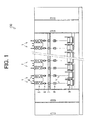
- the spinning machine 100 includes a plurality of the spinning units 1.
- the spinning machine 100 is provided with one air distributor 2 (not illustrated in Fig. 1 ) (refer to Fig. 7 ) and one additive supplying device 3 (not illustrated in Fig. 1 ) (refer to Fig. 7 ).
- the spinning unit 1 produces a spun yarn Y from a fiber bundle F and forms a package P.
- the spinning unit 1 is provided with a sliver supplying unit 4, a draft device 5, an air-jet spinning device 6, a yarn defect detecting device 7, a tension stabilizing device 8, and a winding device 9, which are arranged in this order in the direction in which the fiber bundle F and the spun yarn Y are fed.
- the sliver supplying unit 4 supplies the fiber bundle F, which is raw materials for the spun yarn Y, to the draft device 5.
- the sliver supplying unit 4 includes a sliver case 41 and a sliver guide 42 (refer to Fig. 3 ).
- the fiber bundle F accumulated in the sliver case 41 is supplied to the draft device 5 by being guided by the sliver guide 42.
- the draft device 5 drafts the fiber bundle F to equalize the thickness of the fiber bundle F.
- the draft device 5 includes the following four pairs of draft rollers: a back roller pair 51, a third roller pair 52, a middle roller pair 53 provided with an apron band 53C, and a front roller pair 54, all of which are arranged in this order in the direction in which the fiber bundle F is fed. Arrows in Fig. 3 indicate the direction in which the fiber bundle F is fed.
- the four draft roller pairs 51, 52, 53 and 54 consist of bottom rollers 51A, 52A, 53A and 54A and top rollers 51B, 52B, 53B and 54B, respectively.
- the bottom rollers 51A, 52A, 53A and 54A are rotated by a driving device (not illustrated) in the same direction.
- the top rollers 51B, 52B, 53B and 54B are rotated in the same direction in response to the rotation of the bottom rollers 51A, 52A, 53A and 54A.
- the rotation speed of each of the draft roller pairs 51, 52, 53 and 54 is set such that the rotation speed gradually increases along the direction in which the fiber bundle F is fed.
- the air-jet spinning device 6 produces the spun yarn Y by twisting the drafted fiber bundle F.
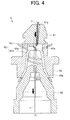
- the air-jet spinning device 6 includes a fiber guide (fiber guiding section) 61, a spindle (hollow guide shaft body) 62, and a nozzle block 63.
- Black arrows in Fig. 4 indicate the direction in which the fiber bundle F and the spun yarn Y are fed.
- White arrows in Fig. 4 indicate the direction in which the supplied air flows.
- the fiber guide 61 constitutes a portion of a spinning chamber SC.
- the fiber guide 61 guides the fiber bundle F drafted by the draft device 5 to the spinning chamber SC.
- the fiber guide 61 guides the fiber bundle F into the spinning chamber SC through a fiber introducing passage 61g connected to the spinning chamber SC.
- the fiber guide 61 is provided with a needle 61n projecting into the spinning chamber SC so as to guide the fiber bundle F therealong.
- the spindle 62 constitutes a portion of the spinning chamber SC.
- the spindle 62 guides the fiber bundle F twisted in the spinning chamber SC, that is, the spun yarn Y, to the yarn defect detecting device 7.
- the spindle 62 guides the spun yarn Y to the yarn defect detecting device 7, which is arranged downstream in the feeding direction, through a fiber passage 62s connected to the spinning chamber SC.
- the nozzle block 63 constitutes a portion of the spinning chamber SC.
- the nozzle block 63 guides the compressed air fed by a compressed air feeding device 21, which will be described later, to the spinning chamber SC.
- the nozzle block 63 guides the air into the spinning chamber SC through air holes 63a connected to the spinning chamber SC.
- Each air hole 63a of the nozzle block 63 is connected to the spinning chamber SC so that the air injected from each of the air holes 63a flows in the same direction around a central axis of the spinning chamber SC. Accordingly, whirling airflow can be generated in the spinning chamber SC (refer to the white arrows in Fig. 4 ).
- the spinning chamber SC is a space surrounded by the fiber guide 61, the spindle 62, and the nozzle block 63.
- the spinning chamber SC is a space formed by being surrounded by the substantially conical spindle 62 which is inserted from one end of a substantially conical through-hole 63p of the nozzle block 63, and the fiber guide 61 which is attached to the other end of the through-hole 63p.
- the spinning chamber SC is divided into two sections: a space SC1, which is formed between the fiber guide 61 and the spindle 62, and a space SC2, which is formed between the spindle 62 and the nozzle block 63.
- a space SC1 which is formed between the fiber guide 61 and the spindle 62
- a space SC2 which is formed between the spindle 62 and the nozzle block 63.
- a trailing end of each fiber of the fiber bundle F is reversed by whirling airflow (refer to two-dot chain lines in Fig. 4 ).
- the trailing end of the reversed fiber is whirled by the whirling airflow (refer to two-dot chain lines in Fig. 4 ).
- the trailing end of each fiber of the fiber bundle F guided along the needle 61n is whirled and gradually wound around core fibers.
- the air-jet spinning device 6 can twist the fiber bundle F using the whirling airflow and produce the spun yarn Y as described above.
- the air-jet spinning device 6 may be provided with the fiber guide 61 without the needle 61n. In this case, a downstream edge of the fiber guide 61 performs a function of the needle 61.
- the yarn defect detecting device 7 detects a defective portion occurred in the spun yarn Y.
- the yarn defect detecting device 7 includes a light source section 71, a light receiving section 72, and a casing 73. Arrows in Fig. 5 indicate the direction of the light emitted from the light source section 71.
- the light source section 71 is a semiconductor element that emits light by voltage being applied in the forward direction, that is, a light emitting diode.
- the light source section 71 is arranged so as to irradiate the spun yarn Y with the light therefrom.
- the light receiving section 72 is a semiconductor element that enables control of an electric current with a light signal, that is, a phototransistor.
- the light receiving section 72 is arranged so as to receive the light emitted from the light source section 71.
- the casing 73 holds the light source section 71 and the light receiving section 72 at a prescribed position.
- the casing 73 is provided with a yarn path 73a where the spun yarn Y passes through.
- the casing 73 holds the light source section 71 and the light receiving section 72 so as to face one another across the spun yarn Y.
- the quantity of the light that the light receiving section 72 receives is a value that is calculated by subtracting the quantity of the light shielded by the spun yarn Y from the quantity of the light that the light source section 71 irradiates the spun yarn Y.
- the yarn defect detecting device 7 is connected to a control device C via an electric line (refer to Fig. 7 ).
- the control device C receives a detection signal from the yarn detect defecting device 7.
- the defects that the yarn defect detecting device 7 can detect include: a portion of the spun yarn Y that is too thick or too thin, and foreign bodies, such as polypropylenes, contained in the spun yarn Y.
- the yarn defect detecting device 7 may also adopt a capacitive sensor instead of the above-described optical sensor.
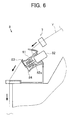
- the tension stabilizing device 8 stabilizes the tension of the spun yarn Y by properly maintaining the tension. As illustrated in Fig. 6 , the tension stabilizing device 8 includes a roller 81, a driving section 82, and an unwinding member 83. Arrows in Fig. 6 indicate the direction in which the spun yarn Y is fed.
- the roller 81 is a rotor in a substantially cylindrical shape that draws the spun yarn Y from the air-jet spinning device 6 and winds the spun yarn Y.
- the roller 81 attached to a rotating axis 82a of the driving section 82 is rotated by the driving section 82.
- the spun yarn Y drawn from the air-jet spinning device 6 is wound around an outer peripheral surface of the roller 81.
- the driving section 82 is an electric motor that is activated when power is supplied.
- the driving section 82 rotates the roller 81 and also maintains a constant rotation speed thereof at a predetermined value. Accordingly, the winding speed of the spun yarn Y wound around the roller 81 can be maintained at the constant speed.
- the unwinding member 83 is a yarn hooking member that assists unwinding the spun yarn Y wound around the roller 81 by being rotated integrally with or independently from the roller 81.
- One end of the unwinding member 83 is attached to a rotating axis 84 of the roller 81.
- the other end of the unwinding member 83 is formed to curve towards the outer peripheral surface of the roller 81.
- the unwinding member 83 enables unwinding of the spun yarn Y from the roller 81 by the spun yarn Y being hooked on the curved portion.
- a permanent magnet (not illustrated) that generates a resistance force against the rotation of the unwinding member 83 is provided at the base of the rotating axis 84 where the unwinding member 83 is attached.
- the tension stabilizing device 8 can rotate the unwinding member 83 integrally with or independently from the roller 81 according to the tension acting upon the spun yarn Y, and can adjust an unwinding speed of the spun yarn Y. Accordingly, the tension stabilizing device 8 stabilizes the tension acting upon the spun yarn Y by properly maintaining the tension.
- the tension stabilizing device 8 draws the spun yarn Y from the air-jet spinning device 6.
- a delivery roller and a nip roller may be provided downstream of the air-jet spinning device 6 to draw the spun yarn Y.
- the tension stabilizing device 8 may be provided downstream of the delivery roller and the nip roller to accumulate the spun yarn Y.
- the spun yarn Y may be drawn with the winding device 9 without arranging the tension stabilizing device 8.
- the winding device 9 produces a substantially cylindrical (cheese-shaped) package P by winding the spun yarn Y.
- the winding device 9 includes a driving roller 91 and a cradle (not illustrated).
- the cradle rotatably holds the bobbin 92.
- the driving roller 91 rotates the bobbin 92 and the package P.
- the bobbin 92 is rotated by the driving roller 91 which rotates while being in contact with an outer peripheral surface of the bobbin 92 or an outer peripheral surface of the package P.
- the winding device 9 traverses the spun yarn Y by a traverse device (not illustrated) while rotating the bobbin 92 to wind the spun yarn Y into the package P.
- the winding device 9 can produce, for example, a substantially conical (cone-shaped) package P other than the substantially cylindrical (cheese-shaped) package P, which is illustrated in Fig. 2 .
- FIG. 7 a description will be made on the structure of the air distributor 2 and the additive supplying device 3. Arrows in Fig. 7 indicate the direction in which air flows.
- the spinning machine 100 is provided with one air distributor 2.
- the air distributor 2 includes a compressed air feeding device 21, a first air pipe 22, a first distribution pipe 23, a second air pipe 24 and a second distribution pipe 25.
- the compressed air feeding device 21 compresses air and feeds the air. Although a detailed illustration is omitted, the compressed air feeding device 21 is an electric compressor or the like that compresses the air by activating an electric motor. The pressure of the air compressed and fed by the compressed air feeding device 21 is adjusted with a pressure adjusting valve 211.
- the first air pipe 22 functions as an air passage where the air compressed and fed by the compressed air feeding device 21 is guided.
- the first air pipe 22 is mounted in parallel or substantially in parallel along the direction in which each spinning unit 1 is allocated.
- the first distribution pipe 23 functions as an air passage where the air flowing in the first air pipe 22 branches off and then is guided to the air-jet spinning devices 6.
- One end of the first distribution pipe 23 is connected to the air-jet spinning device 6.
- the other end of the first distribution pipe 23 is connected to an intermediate portion of the first air pipe 22. Accordingly, the first distribution pipe 23 can branch off the air flowing in the first air pipe 22 and guide the air to the air-jet spinning devices 6. Further, the volume of the air to be guided to the air-jet spinning device 6 through the first distribution pipe 23 is adjusted by an open/close valve 231 provided in the first distribution pipe 23.
- the second air pipe 24 functions as an air passage where the air compressed and fed by the compressed air feeding device 21 is guided.
- the second air pipe 24 is mounted in parallel or substantially in parallel along the direction in which each spinning unit 1 is allocated.
- the second distribution pipe 25 functions as an air passage where the air flowing in the second air pipe 24 branches off and then is guided to the air-jet spinning devices 6.
- One end of the second distribution pipe 25 is connected to the air-jet spinning device 6.
- the other end of the second distribution pipe 25 is connected to an intermediate portion of the second air pipe 24. Accordingly, the second distribution pipe 25 can branch off the air flowing in the second air pipe 24 and guide the air to the air-jet spinning devices 6. Further, the volume of the air to be guided to the air-jet spinning device 6 through the second distribution pipe 25 is adjusted by an open/close valve 251 provided in the second distribution pipe 25.
- the air distributor 2 can supply the air compressed and fed by the compressed air feeding device 21 to the air-jet spinning devices 6 through the first air pipe 22 or the second air pipe 24.
- the second air pipe 24 may be omitted.
- a larger number of air pipes may be provided than the spinning machine 100 according to the present embodiment.
- the spinning machine 100 is provided with one additive supplying device 3.
- the additive supplying device 3 includes a branching pipe 31, a pressure adjusting device 32, an additive storage tank 33, and an additive supplying pipe 34.
- the branching pipe 31 functions as an air passage where the air flowing in the first air pipe 22 branches off and then is guided to the additive storage tank 33.
- One end of the branching pipe 31 is connected to the additive storage tank 33.
- the other end of the branching pipe 31 is connected to the intermediate portion of the first air pipe 22. Accordingly, the branching pipe 31 can branch off the air flowing in the first air pipe 22 and guide the air to the additive storage tank 33.
- the volume of the air to be guided to the additive storage tank 33 through the branching pipe 31 is adjusted by a valve 311 provided in the branching pipe 31.
- the pressure adjusting device 32 adjusts the pressure inside the additive storage tank 33 by compressing the air guided thereto.
- the pressure adjusting device 32 includes a booster valve and the like that compresses the air by driving a sliding piston (not illustrated).
- the pressure adjusting device 32 may be an electric compressor that compresses the air by driving an electric motor (not illustrated).
- the pressure adjusting device 32 is connected to the control device C via an electric line.
- the control device C appropriately controls an operating state of the pressure adjusting device 32 by transmitting a control signal to the pressure adjusting device 32.
- the additive storage tank 33 is a container to store an additive.
- the additive storage tank 33 is provided with a level sensor 331 that detects a stored volume of the additive.
- the level sensor 331 is connected to the control device C via an electric line.
- the control device C detects the stored volume of the additive upon reception of a detection signal from the level sensor 331.
- the additive supplying pipe 34 functions as an air passage where the additive stored in the additive storage tank 33 is guided to the first air pipe 22.
- One end of the additive supplying pipe 34 is connected to the additive storage tank 33 and is opened at the bottom of the additive storage tank 33.
- the other end of the additive supplying pipe 34 is connected to the first air pipe 22 at the upstream of a branch where the air flowing in the first air pipe 22 branches off towards each of the air-jet spinning devices 6.
- the additive supplying device 3 can supply the additive stored in the additive storage tank 33 to the first air pipe 22.
- the additive supplying device 3 can adjust the supplying volume of the additive by adjusting the pressure inside the additive storage tank 33.
- the additive applies at least one of an antibacterial function, an odor preventing function, an odor eliminating function and an unwinding function to the spun yarn Y.
- the additive supplying device 3 can apply additives of mixture of functions to the spun yarn Y. By supplying liquid wax as an additive for an unwinding function, a solid wax is not necessary to be provided in each of the spinning units 1. In an embodiment of the present invention, the additive is not limited to the above described examples.
- the additive supplying device 3 may supply another additive such as an accumulation preventing agent that can prevent an oil agent applied to the fiber bundle F from accumulating on the spindle 62.
- the spinning machine 100 can supply an additive to the air to be supplied to the air-jet spinning device 6, and also, in spite of a simple structure, can adjust the supplying volume of the additive with high accuracy. Accordingly, the volume of the additive supplied to the air-jet spinning devices 6 can be prevented from being excessive or deficient.
- the control device C controls the additive supplying device 3 such that the additive of a weight of at least 0.01% and at most 0.2% of a weight of the produced spun yarn Y per unit length is supplied. Accordingly, even if an additive is mixed to the air to be supplied to each air-jet spinning device 6, functionality can be applied to the spun yarn Y without affecting the spinning function using whirling airflow, and quality of the spun yarn Y can be improved.
- the additive supplying device 3 supplies an additive to the plurality of the air-jet spinning devices 6, and therefore, functionality can be applied to the spun yarn Y by the plurality of the air-jet spinning devices 6 without introducing an additional process. Since the single additive supplying device 3 can supply an additive to the plurality of the air-jet spinning devices 6, a structure of the spinning machine 100 can be simplified.
- the spinning machine 100 can supply air to the air-jet spinning devices 6 using only the first air pipe 22 by opening a valve 221 provided upstream of the first air pipe 22 and by closing a valve 241 provided upstream of the second air pipe 24. Accordingly, only the air containing the additive can be supplied to the air-jet spinning devices 6.
- the spinning machine 100 can supply the air to the air-jet spinning devices 6 using only the second air pipe 24 by closing the valve 221 provided upstream of the first air pipe 22 and by opening the value 241 provided upstream of the second air pipe 24. Accordingly, only the air that does not contain an additive can be supplied to the air-jet spinning devices 6.
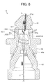
- the space SC1 and the space SC2 of the spinning chamber SC are filled with the air containing the additive supplied by the compressed air feeding device 2 and the additive supplying device 3.
- the air containing the additive is injected from the air holes 63a and whirling airflow is generated.
- each fiber of the fiber bundle F is reversed and whirled by the whirling airflow in the space SC2 (refer to two-dot chain lines in Fig. 8 ).
- the additive contained in the whirling airflow is adhered to each whirling fiber.
- the additive contained in the air filled in the space SC 1 is adhered to the fiber bundle F guided along the needle 61n.
- the trailing end of each fiber to which the additive has adhered is whirled and continuously wound around core fibers.
- the fiber bundle F is produced into the spun yarn Y while the additive is adhered to the fibers by the whirling airflow.
- the spun yarn Y to which the additive has adhered is wound around the outer peripheral surface of a bobbin B rotatably held by the winding device 9.
- the winding device 9 forms a package P of the spun yarn Y to which the additive has adhered.
- the spinning machine 100 can apply functionality to the spun yarn Y without introducing an additional process and also produce the package P without affecting the functionality of the spun yarn Y as described above.
- FIG. 9 a description will be made on a control mode of adjusting the supplying volume of the additive according the number of the operating air-jet spinning devices 6.
- a horizontal axis in Fig. 9 indicates the number of the operating air-jet spinning devices 6.
- a vertical axis in Fig. 9 indicates a ratio of the actually supplied volume to the supplying volume of the additive when all of the air-jet spinning devices 6 are operating.
- the spinning machine 100 increases the supplying volume of the additive according to an increase in the number of the operating air-jet spinning devices 6.
- the control device C of the spinning machine 100 increases the supplying volume of the additive according to the increase in the number of the operating air-jet spinning devices 6 by controlling the pressure adjusting device 32 of the additive supplying device 3.
- the spinning machine 100 reduces the supplying volume of the additive according to a decrease in the number of the operating air-jet spinning devices 6.
- the control device C of the spinning machine 100 reduces the supplying volume of the additive according to the decrease in the number of the operating air-jet spinning devices 6 by controlling the pressure adjusting device 32 of the additive supplying device 3.
- the spinning machine 100 adjusts the supplying volume of the additive gradually (step-by-step) according to the number of the operating air-jet spinning devices 6. However, as indicated by a dotted line in Fig. 9 , the spinning machine 100 can also continuously adjust the supplying volume of the additive.
- the control device C adjusts the supplying volume of the additive by controlling a ratio of operating time to non-operating time of the pressure adjusting device 32 per unit time, that is, by controlling a duty ratio of the pressure adjusting device 32.
- the supplying volume of the additive may be adjusted by controlling a differential pressure with a regulator (not illustrated) or by directly controlling the volume of the additive supplied by the additive supplying device 3.
- the spinning machine 100 can add the additive to the air to be supplied to the air-jet spinning devices 6 and also adjust the supplying volume of the additive according to the number of the operating air-jet spinning devices 6. Accordingly, the volume of the additive supplied to the air-jet spinning devices 6 can be prevented from being excessive or deficient, which leads to improvements in quality of the spun yarn Y.
- control device C of the spinning machine 100 obtains the number of the operating air-jet spinning devices 6.
- the control device C obtains the number of the operating air-jet spinning devices 6 by receiving an electrical signal transmitted from each spinning unit 1.
- the control device C obtains the number of the operating air-jet spinning devices 6 by receiving a signal containing an operating state from each spinning unit 1.
- the control device C obtains the number of the operating air-jet spinning devices 6 by receiving a yarn travelling signal transmitted from the yarn defect detecting device 7.
- the control device C can obtain the number of the operating air-jet spinning devices 6 by a yarn travelling signal or the like from such a sensor.
- the control device C may also obtain the number of the operating air-jet spinning devices 6 in accordance with a measurement result of an air flow-rate measuring device 222 provided in the first air pipe 22.
- the control device C uses a correlation between the volume of the air flowing in the first air pipe 22 and the number of the operating air-jet spinning devices 6.
- a hot-wire flowmeter or a pressure-differential type flowmeter or the like may be used as the air flow-rate measuring device 222, and a measuring method is not limited.
- the spinning machine 100 can correctly obtain the number of the operating air-jet spinning devices 6, and properly adjust the supplying volume of the additive. Accordingly, the volume of the additive to be supplied to the air-jet spinning devices 6 can be prevented from being excessive or deficient, which leads to improvements in quality of the spun yarn Y.
- the additive supplying device 3 supplies an additive or the like to the first air pipe 22.
- a large volume of the additive adhering to the inside of the first air pipe 22 may possibly flow into the air-jet spinning devices 6.
- the first air pipe 22 is arranged inclined so that the additive adhering to the inside of the first air pipe 22 is guided to a prescribed position. Accordingly, the additive adhering to the inside of the first air pipe 22 can be prevented from flowing into the air-jet spinning device 6, which leads to improvements in quality of the spun yarn Y.
- the first air pipe 22 is provided with an additive discharge port 223 arranged to drain the additive accumulated in the first air pipe 22. Accordingly, the additive accumulated in the first air pipe 22 can be prevented from flowing into the air-jet spinning device 6, which leads to improvements in quality of the spun yarn Y.
- the first air pipe 22 is arranged to be inclined further downward in the height direction of the spinning machine 100 as the distance from the additive supplying device 3 increases.
- the arrangement of the first air pipe 22 is not limited to this, and, for example, the first air pipe 22 may be arranged to be inclined further upward in the height direction of the spinning machine 100 as the distance from the additive supplying device 3 increases.
- the additive discharge port 223 is arranged in the vicinity of the additive supplying device 3.
- the additive adhering to the inside of the first air pipe 22 may be collected to the additive storage tank 33 from the additive discharge port 223.
- the spinning machine 100 includes one additive supplying device 3.
- each group may be provided with one additive supplying device 3 and one compressed air feeding device 21.
- one additive supplying device 3 and one compressed air feeding device 21 By arranging one additive supplying device 3 and one compressed air feeding device 21 for the plurality of the spinning units 1, an entire structure of the spinning machine 100 can be simplified and the increase in the size of the spinning machine 100 can be avoided.
- each spinning unit 1 may be provided with an individual additive supplying device 3. In this case, different types of the additive can be supplied in different spinning units 1.
- the fiber bundle F is fed from an upward position to a downward position in the height direction of the spinning machine 100.
- the spinning machine 100 is not limited to such an embodiment.
- a can storing the fiber bundle F may be provided at a lower portion of the spinning machine 100, and the winding device 9 may be provided at an upper portion of the spinning machine 100.
- the air-jet spinning device 6 provided in the spinning unit 1 is not limited to the above-described embodiment.
- a pair of air-jet nozzles that applies twists in opposite directions may be adopted.
Landscapes
- Engineering & Computer Science (AREA)
- Mechanical Engineering (AREA)
- Textile Engineering (AREA)
- Spinning Or Twisting Of Yarns (AREA)
- Yarns And Mechanical Finishing Of Yarns Or Ropes (AREA)
Applications Claiming Priority (1)
| Application Number | Priority Date | Filing Date | Title |
|---|---|---|---|
| JP2011206505A JP2013067893A (ja) | 2011-09-21 | 2011-09-21 | 紡績機及び紡績糸の製造方法 |
Publications (2)
| Publication Number | Publication Date |
|---|---|
| EP2573256A2 true EP2573256A2 (de) | 2013-03-27 |
| EP2573256A3 EP2573256A3 (de) | 2014-03-12 |
Family
ID=46750199
Family Applications (1)
| Application Number | Title | Priority Date | Filing Date |
|---|---|---|---|
| EP12179703.9A Withdrawn EP2573256A3 (de) | 2011-09-21 | 2012-08-08 | Spinnmaschine und Verfahren zur Herstellung von gesponnenem Garn |
Country Status (3)
| Country | Link |
|---|---|
| EP (1) | EP2573256A3 (de) |
| JP (1) | JP2013067893A (de) |
| CN (1) | CN103014938A (de) |
Cited By (4)
| Publication number | Priority date | Publication date | Assignee | Title |
|---|---|---|---|---|
| EP2955256A1 (de) * | 2014-06-12 | 2015-12-16 | Maschinenfabrik Rieter Ag | Luftspinnmaschine sowie verfahren zum betrieb einer solchen |
| EP2949795A3 (de) * | 2014-05-27 | 2016-03-23 | Murata Machinery, Ltd. | Spinnverfahren, spinnmaschine und garn |
| EP3321398A1 (de) * | 2016-11-07 | 2018-05-16 | Murata Machinery, Ltd. | Spinnmaschine und spinnverfahren |
| LU504422B1 (de) * | 2023-06-06 | 2024-12-06 | Saurer Spinning Solutions Gmbh & Co Kg | Luftspinnmaschine und Verfahren |
Families Citing this family (6)
| Publication number | Priority date | Publication date | Assignee | Title |
|---|---|---|---|---|
| CN103789891B (zh) * | 2013-12-30 | 2015-11-04 | 中原工学院 | 功能性转杯纺纱线的粉末施加辅助装置及加工方法 |
| CH709615A1 (de) * | 2014-05-13 | 2015-11-13 | Rieter Ag Maschf | Spinnstelle einer Luftspinnmaschine sowie Betrieb einer solchen. |
| JP2017002431A (ja) * | 2015-06-11 | 2017-01-05 | 村田機械株式会社 | 紡績機及び紡績方法 |
| JP2021113378A (ja) * | 2020-01-21 | 2021-08-05 | 村田機械株式会社 | 空気紡績機 |
| CN112626627B (zh) * | 2020-12-09 | 2021-11-12 | 山东精恒科技有限公司 | 一种喷射上油机构以及对位芳纶纤维双面上油装置 |
| CN113046875B (zh) * | 2021-01-29 | 2022-09-06 | 安徽省金士棉机有限责任公司 | 一种环锭纺纱瑕疵产品剔除装置 |
Citations (4)
| Publication number | Priority date | Publication date | Assignee | Title |
|---|---|---|---|---|
| FR1382957A (fr) * | 1962-08-16 | 1964-12-24 | Pavena Ag | Procédé de fabrication d'un fil tordu |
| US3548462A (en) * | 1964-02-15 | 1970-12-22 | Pavena Ag | Process for the preparation of a fiber arrangement or strand composed of staple fibers for undergoing a subsequent high draft |
| JP2009001935A (ja) | 2007-06-21 | 2009-01-08 | Murata Mach Ltd | 紡績装置 |
| JP2009270208A (ja) | 2008-05-01 | 2009-11-19 | Ohara Palladium Kagaku Kk | 繊維用抗菌防臭加工剤並びに該加工剤で加工処理されてなる繊維製品。 |
Family Cites Families (9)
| Publication number | Priority date | Publication date | Assignee | Title |
|---|---|---|---|---|
| NL150527B (nl) * | 1974-08-21 | 1976-08-16 | Hollandse Signaalapparaten Bv | Valstwistorgaan alsmede de werkwijze voor het vervaardigen van twistloos of nagenoeg twistloos garen en voor het aanbrengen van kleurstoffen in getwist garen met behulp van dit valstwistorgaan. |
| DE4007389C1 (de) * | 1990-03-08 | 1991-05-16 | Zinser Textilmaschinen Gmbh, 7333 Ebersbach, De | |
| FR2724947A1 (fr) * | 1994-09-28 | 1996-03-29 | Vanhelle Michel Eugene Albert | Organe de fausse torsion |
| JP3538510B2 (ja) * | 1996-11-06 | 2004-06-14 | 株式会社フコク | 繊維質産業資材の製造装置 |
| JPH10147473A (ja) * | 1996-11-19 | 1998-06-02 | Murata Mach Ltd | 自動ワインダー |
| JP3925533B2 (ja) * | 2004-11-05 | 2007-06-06 | 村田機械株式会社 | 紡績装置、及び繊維蓄積状態の検出方法 |
| JP2009242972A (ja) * | 2008-03-31 | 2009-10-22 | Murata Mach Ltd | 紡績装置 |
| JP2011084854A (ja) * | 2009-09-18 | 2011-04-28 | Murata Machinery Ltd | 紡績機 |
| JP2012097391A (ja) * | 2010-11-05 | 2012-05-24 | Murata Mach Ltd | 紡績機 |
-
2011
- 2011-09-21 JP JP2011206505A patent/JP2013067893A/ja active Pending
-
2012
- 2012-06-19 CN CN2012102081292A patent/CN103014938A/zh active Pending
- 2012-08-08 EP EP12179703.9A patent/EP2573256A3/de not_active Withdrawn
Patent Citations (4)
| Publication number | Priority date | Publication date | Assignee | Title |
|---|---|---|---|---|
| FR1382957A (fr) * | 1962-08-16 | 1964-12-24 | Pavena Ag | Procédé de fabrication d'un fil tordu |
| US3548462A (en) * | 1964-02-15 | 1970-12-22 | Pavena Ag | Process for the preparation of a fiber arrangement or strand composed of staple fibers for undergoing a subsequent high draft |
| JP2009001935A (ja) | 2007-06-21 | 2009-01-08 | Murata Mach Ltd | 紡績装置 |
| JP2009270208A (ja) | 2008-05-01 | 2009-11-19 | Ohara Palladium Kagaku Kk | 繊維用抗菌防臭加工剤並びに該加工剤で加工処理されてなる繊維製品。 |
Cited By (8)
| Publication number | Priority date | Publication date | Assignee | Title |
|---|---|---|---|---|
| EP2949795A3 (de) * | 2014-05-27 | 2016-03-23 | Murata Machinery, Ltd. | Spinnverfahren, spinnmaschine und garn |
| EP2955256A1 (de) * | 2014-06-12 | 2015-12-16 | Maschinenfabrik Rieter Ag | Luftspinnmaschine sowie verfahren zum betrieb einer solchen |
| CN105297196A (zh) * | 2014-06-12 | 2016-02-03 | 里特机械公司 | 喷气纺纱机以及用于运行这种喷气纺纱机的方法 |
| US9663878B2 (en) | 2014-06-12 | 2017-05-30 | Maschinenfabrik Rieter Ag | Air jet spinning machine and method for operating it |
| EP3321398A1 (de) * | 2016-11-07 | 2018-05-16 | Murata Machinery, Ltd. | Spinnmaschine und spinnverfahren |
| CN108060477A (zh) * | 2016-11-07 | 2018-05-22 | 村田机械株式会社 | 纺纱机及纺纱方法 |
| CN108060477B (zh) * | 2016-11-07 | 2021-12-10 | 村田机械株式会社 | 纺纱机及纺纱方法 |
| LU504422B1 (de) * | 2023-06-06 | 2024-12-06 | Saurer Spinning Solutions Gmbh & Co Kg | Luftspinnmaschine und Verfahren |
Also Published As
| Publication number | Publication date |
|---|---|
| EP2573256A3 (de) | 2014-03-12 |
| JP2013067893A (ja) | 2013-04-18 |
| CN103014938A (zh) | 2013-04-03 |
Similar Documents
| Publication | Publication Date | Title |
|---|---|---|
| EP2573256A2 (de) | Spinnmaschine und Verfahren zur Herstellung von gesponnenem Garn | |
| EP2450478B1 (de) | Spinnmaschine | |
| CN108060477B (zh) | 纺纱机及纺纱方法 | |
| US9663878B2 (en) | Air jet spinning machine and method for operating it | |
| CN103787150A (zh) | 纱线卷取机以及纱线卷取方法 | |
| EP2453045B1 (de) | Luftspinnvorrichtung und Spinneinheit | |
| EP2876192A1 (de) | Druckluftspinnvorrichtung und Spinnmaschine | |
| CN104975382A (zh) | 喷气纺纱机以及用于运行喷气纺纱机的方法 | |
| CN105256417B (zh) | 纺纱机械以及纺纱方法 | |
| US20150283747A1 (en) | Spinning Unit of an Air Spinning Machine and a Method for Operating an Air Spinning Machine | |
| EP3012362A2 (de) | Hohler führungszylinder, luftdüsenspinnvorrichtung und textilmaschine | |
| CN106567170A (zh) | 纺织机以及控制装置 | |
| CN108691046A (zh) | 纺纱机 | |
| EP2453044B1 (de) | Spinnverfahren unter Verwendung einer Luftspinnvorrichtung und Luftspinnvorrichtung | |
| CN101052758B (zh) | 一种优化纺纱机产量的方法及纺纱机 | |
| EP2949795A2 (de) | Spinnverfahren, spinnmaschine und garn | |
| CN105966995B (zh) | 接头装置、纺纱机和自动络纱机 | |
| CN106560535A (zh) | 牵伸装置、纺织机以及纺织方法 | |
| JP2018154952A (ja) | 添加剤供給装置、添加剤補給システム、及び添加剤補給制御方法 | |
| CN110552089A (zh) | 空气纺纱机 | |
| CN110029412A (zh) | 纺纱机及纺纱方法 | |
| CN111663210B (zh) | 空气消耗量计算装置、纺纱机、纺纱系统及空气消耗量计算方法 | |
| CN105648591B (zh) | 纤维回收装置、牵伸装置以及纺织机 | |
| CN104562318B (zh) | 牵伸装置及纺织机 | |
| CN105133100B (zh) | 纺纱机及纺纱方法 |
Legal Events
| Date | Code | Title | Description |
|---|---|---|---|
| PUAI | Public reference made under article 153(3) epc to a published international application that has entered the european phase |
Free format text: ORIGINAL CODE: 0009012 |
|
| AK | Designated contracting states |
Kind code of ref document: A2 Designated state(s): AL AT BE BG CH CY CZ DE DK EE ES FI FR GB GR HR HU IE IS IT LI LT LU LV MC MK MT NL NO PL PT RO RS SE SI SK SM TR |
|
| AX | Request for extension of the european patent |
Extension state: BA ME |
|
| PUAL | Search report despatched |
Free format text: ORIGINAL CODE: 0009013 |
|
| AK | Designated contracting states |
Kind code of ref document: A3 Designated state(s): AL AT BE BG CH CY CZ DE DK EE ES FI FR GB GR HR HU IE IS IT LI LT LU LV MC MK MT NL NO PL PT RO RS SE SI SK SM TR |
|
| AX | Request for extension of the european patent |
Extension state: BA ME |
|
| RIC1 | Information provided on ipc code assigned before grant |
Ipc: D06M 16/00 20060101AFI20140206BHEP Ipc: D01H 1/115 20060101ALI20140206BHEP |
|
| 17P | Request for examination filed |
Effective date: 20140707 |
|
| RBV | Designated contracting states (corrected) |
Designated state(s): AL AT BE BG CH CY CZ DE DK EE ES FI FR GB GR HR HU IE IS IT LI LT LU LV MC MK MT NL NO PL PT RO RS SE SI SK SM TR |
|
| 17Q | First examination report despatched |
Effective date: 20150119 |
|
| STAA | Information on the status of an ep patent application or granted ep patent |
Free format text: STATUS: THE APPLICATION HAS BEEN WITHDRAWN |
|
| 18W | Application withdrawn |
Effective date: 20161013 |