EP2573260A1 - Rouleau et procédé de revêtement de rouleau - Google Patents
Rouleau et procédé de revêtement de rouleau Download PDFInfo
- Publication number
- EP2573260A1 EP2573260A1 EP12006614A EP12006614A EP2573260A1 EP 2573260 A1 EP2573260 A1 EP 2573260A1 EP 12006614 A EP12006614 A EP 12006614A EP 12006614 A EP12006614 A EP 12006614A EP 2573260 A1 EP2573260 A1 EP 2573260A1
- Authority
- EP
- European Patent Office
- Prior art keywords
- layer
- roller
- roll
- local
- areas
- Prior art date
- Legal status (The legal status is an assumption and is not a legal conclusion. Google has not performed a legal analysis and makes no representation as to the accuracy of the status listed.)
- Granted
Links
- 238000000576 coating method Methods 0.000 title claims abstract description 22
- 238000010285 flame spraying Methods 0.000 claims abstract description 36
- 238000007761 roller coating Methods 0.000 claims abstract description 7
- 238000000034 method Methods 0.000 claims description 27
- 238000000137 annealing Methods 0.000 claims description 26
- 238000002844 melting Methods 0.000 claims description 24
- 230000008018 melting Effects 0.000 claims description 23
- 239000011148 porous material Substances 0.000 claims description 17
- 239000007921 spray Substances 0.000 claims description 5
- 239000011888 foil Substances 0.000 claims 1
- 238000005496 tempering Methods 0.000 abstract description 29
- 239000011248 coating agent Substances 0.000 abstract description 12
- 239000000463 material Substances 0.000 description 22
- 230000008569 process Effects 0.000 description 18
- 238000009792 diffusion process Methods 0.000 description 16
- XEEYBQQBJWHFJM-UHFFFAOYSA-N Iron Chemical compound [Fe] XEEYBQQBJWHFJM-UHFFFAOYSA-N 0.000 description 12
- 230000007704 transition Effects 0.000 description 12
- 229910045601 alloy Inorganic materials 0.000 description 9
- 239000000956 alloy Substances 0.000 description 9
- 238000010438 heat treatment Methods 0.000 description 9
- 229910052742 iron Inorganic materials 0.000 description 8
- 230000000694 effects Effects 0.000 description 7
- PXHVJJICTQNCMI-UHFFFAOYSA-N Nickel Chemical compound [Ni] PXHVJJICTQNCMI-UHFFFAOYSA-N 0.000 description 5
- 239000000654 additive Substances 0.000 description 5
- 230000008901 benefit Effects 0.000 description 5
- 230000035882 stress Effects 0.000 description 5
- 229910000831 Steel Inorganic materials 0.000 description 4
- 235000012771 pancakes Nutrition 0.000 description 4
- 230000035945 sensitivity Effects 0.000 description 4
- 239000010959 steel Substances 0.000 description 4
- 230000006698 induction Effects 0.000 description 3
- 230000003993 interaction Effects 0.000 description 3
- 238000004886 process control Methods 0.000 description 3
- 238000007751 thermal spraying Methods 0.000 description 3
- 230000008646 thermal stress Effects 0.000 description 3
- 229910001018 Cast iron Inorganic materials 0.000 description 2
- 230000000996 additive effect Effects 0.000 description 2
- 230000002411 adverse Effects 0.000 description 2
- 239000000969 carrier Substances 0.000 description 2
- 230000001186 cumulative effect Effects 0.000 description 2
- 238000007749 high velocity oxygen fuel spraying Methods 0.000 description 2
- 239000007788 liquid Substances 0.000 description 2
- 239000000203 mixture Substances 0.000 description 2
- 229910052759 nickel Inorganic materials 0.000 description 2
- 238000005507 spraying Methods 0.000 description 2
- 238000003892 spreading Methods 0.000 description 2
- 230000007480 spreading Effects 0.000 description 2
- XLYOFNOQVPJJNP-UHFFFAOYSA-N water Substances O XLYOFNOQVPJJNP-UHFFFAOYSA-N 0.000 description 2
- 229910001060 Gray iron Inorganic materials 0.000 description 1
- 238000007792 addition Methods 0.000 description 1
- 238000005275 alloying Methods 0.000 description 1
- 230000015572 biosynthetic process Effects 0.000 description 1
- 238000005219 brazing Methods 0.000 description 1
- 239000000919 ceramic Substances 0.000 description 1
- 230000001143 conditioned effect Effects 0.000 description 1
- 230000008094 contradictory effect Effects 0.000 description 1
- 230000007797 corrosion Effects 0.000 description 1
- 238000005260 corrosion Methods 0.000 description 1
- 230000008878 coupling Effects 0.000 description 1
- 238000010168 coupling process Methods 0.000 description 1
- 238000005859 coupling reaction Methods 0.000 description 1
- 239000013078 crystal Substances 0.000 description 1
- 230000003247 decreasing effect Effects 0.000 description 1
- 230000001419 dependent effect Effects 0.000 description 1
- 238000009826 distribution Methods 0.000 description 1
- 238000010894 electron beam technology Methods 0.000 description 1
- 239000000945 filler Substances 0.000 description 1
- 239000000446 fuel Substances 0.000 description 1
- 238000009499 grossing Methods 0.000 description 1
- 230000003116 impacting effect Effects 0.000 description 1
- 230000001939 inductive effect Effects 0.000 description 1
- 238000004519 manufacturing process Methods 0.000 description 1
- 230000007246 mechanism Effects 0.000 description 1
- 239000000155 melt Substances 0.000 description 1
- 229910052751 metal Inorganic materials 0.000 description 1
- 239000002184 metal Substances 0.000 description 1
- 150000001247 metal acetylides Chemical class 0.000 description 1
- 150000002739 metals Chemical class 0.000 description 1
- 230000001617 migratory effect Effects 0.000 description 1
- 238000000465 moulding Methods 0.000 description 1
- 150000004767 nitrides Chemical class 0.000 description 1
- 230000035515 penetration Effects 0.000 description 1
- 239000004033 plastic Substances 0.000 description 1
- 238000012805 post-processing Methods 0.000 description 1
- 238000012545 processing Methods 0.000 description 1
- 230000001105 regulatory effect Effects 0.000 description 1
- 230000004044 response Effects 0.000 description 1
- 238000005096 rolling process Methods 0.000 description 1
- 238000009751 slip forming Methods 0.000 description 1
- 229910000679 solder Inorganic materials 0.000 description 1
- 238000004544 sputter deposition Methods 0.000 description 1
- 239000010935 stainless steel Substances 0.000 description 1
- 229910001220 stainless steel Inorganic materials 0.000 description 1
- 239000000758 substrate Substances 0.000 description 1
Images


Classifications
-
- D—TEXTILES; PAPER
- D21—PAPER-MAKING; PRODUCTION OF CELLULOSE
- D21F—PAPER-MAKING MACHINES; METHODS OF PRODUCING PAPER THEREON
- D21F3/00—Press section of machines for making continuous webs of paper
- D21F3/02—Wet presses
- D21F3/10—Suction rolls, e.g. couch rolls
- D21F3/105—Covers thereof
-
- D—TEXTILES; PAPER
- D21—PAPER-MAKING; PRODUCTION OF CELLULOSE
- D21G—CALENDERS; ACCESSORIES FOR PAPER-MAKING MACHINES
- D21G1/00—Calenders; Smoothing apparatus
- D21G1/02—Rolls; Their bearings
- D21G1/0246—Hard rolls
Definitions
- the invention relates to a roller coated with a high-speed flame spray applied layer and to a roller coating method.
- calender rolls For paper rolls, in particular for calender rolls, corresponding roll coating processes or rolls coated with a layer are known, for example, from US Pat DE 10 2008 037 999 A1 , from the DE 10 2009 045 824 A1 and from the DE 10 2008 044 369 A1 known.
- the calender roll is first coated with an elastic layer and then applied a further layer by a high-velocity flame spraying (high velocity oxy fuel, HVOF process) on the elastic layer.
- HVOF process high velocity oxy fuel
- HVOF process high velocity oxy fuel
- high speed flame spraying with proper process control, ensures that the sprayed material penetrates into pores or other openings on the surface of the elastic layer and then forms a closed layer which has good adhesion to the elastic layer.
- the thermal spraying comprises processes for the production of layers and moldings in which pointed additives, that is to say the materials to be sprayed on, inside or outside of sprayers, are melted off or melted onto spin-coated surfaces of workpieces.
- the sprayed layers can be applied from spray additives in the liquid or plastic state.
- the surfaces of the workpieces are not melted, so that, in particular, thermally sensitive surfaces can be reliably coated with such processes.
- Advantage of the thermal spraying is that the coated workpieces are heated only slightly, so that undesirable structural changes of Base material and distortion of the components are avoided.
- a layer thickness of approximately 10 ⁇ m is to be used as lower limits at the present time.
- Conventionally produced sprayed layers are sensitive to edge pressure, point and line loads and impact stress, which is particularly due to the fact that thermal sprayed layers are stabilized substantially only due to shrinkage processes and adhesion forces between individual structural elements or to the respective substrate.
- these layers are to be thermally treated for a long time, so that the pores outgas.
- a temperature in the order of magnitude of the melting temperature of the sprayed layer material must be selected for this purpose and maintained for a longer time.
- a roller coated with a high-speed flame spray applied layer may be characterized in that the layer has non-annealed areas adjacent to local annealing areas and / or local, spiral or spirally arranged annealing areas.
- certain inherent elasticities can be left in the layer, as a result of which the layer as a whole remains less sensitive.
- a roll coating process in which a roll surface is first coated by means of high-speed flame spraying, wherein the layer applied by means of high-speed flame spraying and / or the coated surface are then locally tempered, can be characterized in that the local temperature control is spiral or in a spiral arrangement and / or local Areas are not tempered
- the spiral-shaped annealing areas make it possible to have certain regulating effects on the position of a material conveyed by the roller or passing past the roller, such as a paper web, although the actual layer does not have any unevennesses that are significant in the required smoothness of the layer need to have.
- a material conveyed by the roller or passing past the roller such as a paper web
- the actual layer does not have any unevennesses that are significant in the required smoothness of the layer need to have.
- the material for example, in the direction of rotation of the roller to the left running spiral exert a force to the left of the roller on the material, which can be used with appropriate design of all components for straightening or smoothing operations.
- spiral annealing areas comprise at least two counter-rotating spirals
- spreading effects or centering effects can be exerted by the spirals on the material, in particular on a paper web.
- the local spiral annealing areas need not be continuously formed as a spiral. Rather, it is also possible to arrange a plurality of individual local annealing areas on, next to and above one another or overlapping, that on average follows a spiral basic structure of the layer, which consists of local spiral annealing areas. Likewise, several rectified spirals or a multi-start spiral can be provided.
- At least one of the non-annealed areas may be enclosed by the local annealing areas arranged next to it, so that ultimately the non-annealed area is protected by them and nevertheless allows a corresponding coupling between the local annealing areas.
- one of the non-annealed areas may be located at an edge of the layer, where possibly a not so strong stress of the layer is to be found and possibly a temperature even adverse effects, such as excessive thermal stress on an edge located at the edge, would require.
- a roll surface may first be coated by high speed flame spraying and the roll coating process characterized by subsequently tempering the layer applied by high velocity flame spraying and / or the coated surface.
- the adjoining tempering which at first appears to be contradictory in view of the low pore density and the already very compact layer, also requires that the structural elements or piles of the layer applied by means of high-speed flame spraying be metallurgically bonded to one another or to the roll body or the coated surface , This can be tempered, especially at much lower temperatures and possibly also for a much shorter time, which is much more gentle on the material.
- the tempering preferably takes place in such a way that the structural elements are connected to one another or to the roll body via a diffusion layer.
- a roll coating method is advantageous in which a roll surface is first coated and which is characterized in that the layer and / or the coated surface are subsequently tempered locally.
- a roll surface is first coated and which is characterized in that the layer and / or the coated surface are subsequently tempered locally.
- the term "tempering” refers to a targeted heat treatment after the respective application of the layer or after the flame spraying or high-speed flame spraying.
- the tempering can be done globally by subjecting the entire roll to a heat treatment. If necessary, care must be taken to ensure that the temperature introduced does not become too great, as a result of which the coated surface or the roller body suffers. If the targeted heat treatment is carried out locally, it may be possible to work with higher energy densities, as long as the total energy is also chosen such that the roll body or the coated surface does not suffer.
- electron beams, lasers, induction coils, flames and / or microwaves are suitable as heat sources for local temperature control.
- suitable interaction mechanisms by focusing or by selecting suitable interaction mechanisms, only or essentially the coated surface can be locally tempered, if this appears to be necessary for good metallic bonding of the structural elements or slabs to the coated surface. Possibly. can also be used from the outgoing heating to temper the overlying layer accordingly and to produce a metallurgical connection of the structural elements or flat with each other.
- an interaction process or a focusing can be selected, which acts only on the layer that has been applied as a coating, where appropriate, a heating to the coated surface is sought in order to ensure a good metallurgical connection there.
- local temperature control has the advantage that the heat sources used for this purpose can generally be controlled much better in terms of their temperature response and also with regard to their energy input into the applied layer or roller, so that, in particular, if necessary, also a local melting, which occurs in usually temperature variations above 5 ° C not tolerated, can be provided.
- a melting of the applied layer can also take place.
- Appropriate further measures can be used to avoid and / or minimize the effects of any processes that occur uncontrollably or lead to uncontrollable results. For example, a sufficiently small area may be melted so that adhesion and cohesive forces hold the molten layer in place.
- separate local areas ie areas spatially limited on all sides, can each be melted one behind the other, so that a region that has once been melted can only harden again before an area adjacent to or overlapping it is melted.
- the roll to be tempered accordingly can be aligned in such a way that the temperature-controlled area is at the top so that flow processes or droplet formation can be avoided.
- temper the applied layer without melting, so that the thermal load of the roller body or the coated surface is reduced to a minimum. This is particularly advantageous when it has been coated over a high-speed flame spraying method or a comparable method, so that from the outset with a very small number of pores is to be expected.
- tempering preferably only surface effects between the individual structural elements or pancakes and / or between the structural elements or pancake and the coated surface are effective, which consequently leads to a better connection, in particular to a metallurgical connection.
- the temperature in such a way that diffusion processes take place relative to the structural elements with one another or else between the structural elements and the roll body or the coated surface. These lead to a particularly intimate metallurgical connection, so that the coating can be made substantially more stable without unnecessarily increasing the thermal load.
- the tempering is preferably carried out at least 1.5%, preferably at least 2 or 3% below the melting temperature of the applied layer to ensure that melting does not occur even in smaller areas.
- a roller coated with a layer is correspondingly advantageous, which is characterized in that the layer has local annealing areas. If tempering is effected locally, be it by webs, for example, by guiding an induction head, an electron gun or a microwave radiator around a roll in a line-like manner, then tempering which places little stress on the roll body or the coated surface can be ensured. The same applies if a corresponding energy source is traversed to different locations. In such a procedure, transition structures are formed in the crystal structure of the tempered layer at the edge of a respective region which is swept by the energy source, in which the diffusion processes have taken place less or more excessively or in which structural transitions are to be found. Such transition regions define in the manner of a border in each case an annealing region and are accordingly an indication that was tempered locally according to the above-described roller coating process.
- the present invention is particularly suitable for large rolls, ie for rolls whose shell length is 2.5 m and / or whose diameter exceeds 350 mm. Due to the local temperature can be dispensed with correspondingly large ovens, in which such rolls would otherwise be tempered.
- the very gentle coating in particular by high-speed flame spraying in conjunction with relatively low tempering temperatures or in conjunction with local tempering, makes the present invention particularly suitable for hollow rolls, that is to say for rolls which are not solidly formed. This suitability applies in particular to thin-walled hollow rolls in which the wall thickness of the roll mantle is less than 10%, preferably less than 5%, of the roll diameter.
- Straight hollow rollers and in particular thin-walled hollow rollers but also other large rollers tend to distort too much thermal stress. This can be successfully avoided by the present invention.
- the present invention is particularly suitable for paper and / or film rolls, which often have to have a micrometer-precise surface at 10 meters or more in length.
- present invention can be advantageously used for veneer or suction rolls.
- the coated surface is preferably made of an iron-based alloy, ie iron, steel, stainless steel, cast iron, gray cast iron or chilled cast iron.
- alloys based on nickel with Fe, Cr, B, Si and C are suitable as a layer which is or is applied to the coated surface.
- Co or Fe can also be used cumulatively or alternatively to Ni.
- C usually serves as an additive for the hardness, while B and Si lower the melting temperature.
- the material compositions of the layer are chosen so that it is harder than steel and have a lower melting point than the material of the coated surface, in particular therefore, for example, as steel.
- the melting point of steel is on the order of 1,500 ° C, while the above-mentioned Ni-base alloys have melting points between 950 ° C and 1050 ° C and Fe / Co based melting points between 1050 ° C and 1150 ° C exhibit.
- a local temperature control can also be advantageous when using conventional brazing materials and leads to a non-excessive stress on the roll body or the coated surface.
- such a coating does not have to be provided on the entire roller. Rather, it is also conceivable to coat or temper selected or heavily loaded areas accordingly. In particular, it is also conceivable, for example, to coat a roll with high-speed flame spraying per se in a conventional manner and then only subject the edges of the roll to the above-described tempering processes. In practice, it has been found that often the two roll edges are subject to extreme loads and that there is a considerable risk that corrosion, starting from the roll edges, engages in the interior of the roll. By local temperature only at the edge or by a corresponding coating only at the edge of this disadvantage can be met, especially if otherwise the high-speed flame spraying or otherwise applied coating for the particular application is sufficiently stable.
- the material used for the layers are preferably alloys with a significantly lower melting point than the melting point of the surface to be coated for use.
- alloys having a melting point of approximately up to 1000 ° C can be applied to iron-based roll bodies having melting points of approximately up to 1500 ° C, and it has been found that even at tempering temperatures between 700 ° C and 800 ° C Connection of the structural elements with each other or with the roller body can be ensured, in particular at lower temperatures or - depending on the alloy - at 700 ° C possibly a relatively long time has to be waited until sufficient diffusion processes have taken place, while at higher temperatures - depending on the alloys used - already a little over 700 ° C, especially from 750 ° C, the diffusion processes already take place on acceptable time scales.
- a roller coated with a layer applied by means of high-speed flame spraying is advantageous with respect to insensitivity of the layer, which is characterized in that the layer has tempering ranges.
- the layer has tempering ranges.
- the object stated at the outset also solves a roller coated with a layer applied by means of high-speed flame spraying, which is characterized in that the layer has structural elements which are connected to one another or to a roller body via a diffusion layer.
- such a diffusion layer does not necessarily have to be found continuously in all areas of the layer. Rather, it is important in the result that the layer for the purpose of the roller is sufficiently strong. It is also conceivable that the layer at least locally completely melts on annealing, it being assumed that this local melting is ultimately still so low in its entirety that thereby the roll body or the coated surface is not or only insignificantly disadvantageous is influenced or warped.
- the number of pores in the coating or in the layer can be reduced to less than 10%, preferably to less than 5%.
- Such a low pore density makes corrosive attacks much more difficult to apply to the layer.
- such a low pore density necessitates that an excellent roll surface be made available even if the coating has been regrind several times which is particularly important for the paper and / or film industry.
- roller 1 has a roller body 10, which is formed by a tube 12 and two laterally attached end support 14, which are configured disk-shaped and are connected via welded joints 18 to the tube 12. At the end supports 14 each have a roll neck 16 is welded, so that the roller 1 can rotate in a corresponding fishing.
- the roller 1 is thus designed as a hollow roller, wherein - depending on the concrete implementation of such a roller - and a plurality of carriers which are similar to the end brackets 14 may be provided in the interior of the tube 12.
- the cavity of the hollow cylinder is sealed, as is the case in the present embodiment.
- internally provided carriers can be opened, i. only as a scaffold, be formed.
- the roll 1 is 3 m long and has a diameter of 300 mm with a wall thickness of the tube 12 of 5 mm. Accordingly, the roll 1 is also a hollow roll or thin-walled large roll.
- the surface 19 of the roller body 10 or of the tube 12 is coated with a layer 20. This is done in the present embodiment via high-speed flame spraying, so that the coating consists of individual high-speed flame-sputtering flat 22, which form individual structural elements 23 of the layer 20, in particular in FIG. 2 shown schematically.
- the tube is made of iron, while the layer of a nickel-based alloy with Fe, Cr, B, Si and C as alloying additives.
- the entire roll 1 in order to achieve metallurgical bonding of the structural elements 23 to one another or to the coated surface.
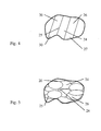
- the adjacent temperature control zones 24, which are separated by transition regions 25 from each other, as in Figures 3 and 4 and 5 are shown schematically.
- the transition regions 25 have a complex structure that is characterized by local temperature-control zones 24 adjoining each other.
- twice as intense diffusion regions between the structural elements 23 with one another or with the coated surface 19 may be present in the transition regions 25 if a sufficient overlap of the respective temperature control zones 24 has been selected.
- transition regions 25 melting is to be found increasingly, if adjacent tempering zones 24 have been tempered in quick succession.
- the tempering zones 24 are often tempered with energy densities having a bell curve or Gaussian distribution curves or the like with energy densities decreasing towards the edge. This can lead to less intensive diffusion regions between the structural elements 23 and to the coated surface 19 being present in the transition regions 25.
- these Transition regions 25 also be no sufficient temperature control to achieve a sufficiently detectable diffusion layer, but this is not critical, as long as such areas are sufficiently small and the stability of the layer 20 overall meets the desired requirements and has been sufficiently stabilized.
- work is done with transition areas 25, which are between 0.1 mm and 3 mm, in particular between 1 mm and 2 mm, which ultimately depends on the accuracy of the management of the energy sources used for temperature control.
- the tube 12 is locally heated by means of an induction head on its surface 19, so that diffusion processes take place between the coated surface 19 and the structural elements 23.
- the heating takes place here at about 800 ° C to 900 ° C, the width of the Temper michszonen 24 in FIG. 4 or the smaller main axis of the Temper michszonen 24 after FIG. 5 is about 10 mm.
- the width or minor major axis of the tempering zones 24 may be between 5 mm and 30 mm, depending on the desired energy densities, the spatial dimensions of the bodies 10 and the materials used, and the desired processing speeds.
- both the layer 20 and the coated surface 19 and the entire roller body 10 are not subject to high thermal loads. It is understood that instead of in the inductive heating in particular, a heating by means of microwaves or by laser is conceivable, which on the one hand depends on the materials and their interaction in the respective energy source and on the other hand on the depth at which the heat is to be applied.
- the thickness of the diffusion layer between the structural elements 23 with each other or to the coated surfaces 19 may be different intense or thick pronounced or that in some areas no such diffusion layers are to be found, which in particular of the time and Frequency with which these were tempered depends. Likewise, it can happen that smaller areas completely melt, which is ultimately not necessary in itself and can involve the risk of excessive thermal stress in itself.
- roller has spiral-shaped annealing areas 27, the 26 formed by appropriate local annealing areas Temper michszonen 24 similar to the arrangement according to FIG. 4 2, which form two counter-rotating spirals 30, 31.
- the roller 1 can after FIG. 6 Centering in the middle or wide spreading from the center out on a paper web or other material on the roller 1 passing material act.
- non-spiral for example, substantially point, circular, or elypsoid-shaped local annealing 26, which are arranged with a spiral-shaped basic structure on the roller 1, such spiral annealing 27 and corresponding spirals 30, 31 can provide.
- the entire layer 20 need not be continuously tempered. Rather, it is also possible to provide non-tempered regions 28, as illustrated by the example of an opening 32 in the roller body 10, which can be arranged, for example, in the region of an edge 29, which revolves around the opening 32.
- non-tempered region 28 and local annealing regions 26 are already flowing due to heat-conducting effects.
- the layer 20, as in FIG. 8 illustrated by way of example extend into a chamfered region of the opening 32.
- this region can leave a focus of a laser or a tempering zone conditioned in some other way, so that there is no longer sufficient heat input and in the region of the edge 29 a non-tempered region 28 follows, which is surrounded by annealing regions 26.
Landscapes
- Coating By Spraying Or Casting (AREA)
Applications Claiming Priority (1)
| Application Number | Priority Date | Filing Date | Title |
|---|---|---|---|
| DE102011113676 | 2011-09-20 |
Publications (2)
| Publication Number | Publication Date |
|---|---|
| EP2573260A1 true EP2573260A1 (fr) | 2013-03-27 |
| EP2573260B1 EP2573260B1 (fr) | 2015-05-13 |
Family
ID=47008232
Family Applications (1)
| Application Number | Title | Priority Date | Filing Date |
|---|---|---|---|
| EP20120006614 Not-in-force EP2573260B1 (fr) | 2011-09-20 | 2012-09-20 | Rouleau et procédé de revêtement de rouleau |
Country Status (2)
| Country | Link |
|---|---|
| EP (1) | EP2573260B1 (fr) |
| DE (1) | DE102012018585A1 (fr) |
Cited By (1)
| Publication number | Priority date | Publication date | Assignee | Title |
|---|---|---|---|---|
| WO2014117759A1 (fr) * | 2013-02-04 | 2014-08-07 | Dirk Richter | Procédé de revêtement, en particulier procédé de revêtement de rouleaux, et corps revêtu, en particulier rouleau revêtu |
Families Citing this family (1)
| Publication number | Priority date | Publication date | Assignee | Title |
|---|---|---|---|---|
| DE102016114014B4 (de) * | 2016-07-29 | 2018-05-17 | Voith Patent Gmbh | Verfahren zur Beschichtung eines Trockenzylinders |
Citations (5)
| Publication number | Priority date | Publication date | Assignee | Title |
|---|---|---|---|---|
| US5283121A (en) * | 1991-11-08 | 1994-02-01 | Bordner Barry A | Corrosion and abrasion resistant industrial roll coating with non-sticking properties |
| DE10354507A1 (de) * | 2003-11-21 | 2005-06-09 | Voith Paper Patent Gmbh | Beschichtung von mit einer Materialbahn in Kontakt tretende Einrichtungen einer Papiermaschine |
| DE102008037999A1 (de) | 2008-08-16 | 2010-02-18 | Voith Patent Gmbh | Verfahren zum Herstellen einer Kalanderwalze und Kalanderwalze |
| DE102008044369A1 (de) | 2008-12-05 | 2010-06-10 | Voith Patent Gmbh | Kalander |
| DE102009045824A1 (de) | 2009-10-20 | 2011-04-21 | Voith Patent Gmbh | Kalander |
-
2012
- 2012-09-20 EP EP20120006614 patent/EP2573260B1/fr not_active Not-in-force
- 2012-09-20 DE DE201210018585 patent/DE102012018585A1/de not_active Withdrawn
Patent Citations (6)
| Publication number | Priority date | Publication date | Assignee | Title |
|---|---|---|---|---|
| US5283121A (en) * | 1991-11-08 | 1994-02-01 | Bordner Barry A | Corrosion and abrasion resistant industrial roll coating with non-sticking properties |
| DE10354507A1 (de) * | 2003-11-21 | 2005-06-09 | Voith Paper Patent Gmbh | Beschichtung von mit einer Materialbahn in Kontakt tretende Einrichtungen einer Papiermaschine |
| DE102008037999A1 (de) | 2008-08-16 | 2010-02-18 | Voith Patent Gmbh | Verfahren zum Herstellen einer Kalanderwalze und Kalanderwalze |
| EP2157234A2 (fr) * | 2008-08-16 | 2010-02-24 | Voith Patent GmbH | Procédé de fabrication d'un cylindre de calandre et cylindre de calandre |
| DE102008044369A1 (de) | 2008-12-05 | 2010-06-10 | Voith Patent Gmbh | Kalander |
| DE102009045824A1 (de) | 2009-10-20 | 2011-04-21 | Voith Patent Gmbh | Kalander |
Cited By (1)
| Publication number | Priority date | Publication date | Assignee | Title |
|---|---|---|---|---|
| WO2014117759A1 (fr) * | 2013-02-04 | 2014-08-07 | Dirk Richter | Procédé de revêtement, en particulier procédé de revêtement de rouleaux, et corps revêtu, en particulier rouleau revêtu |
Also Published As
| Publication number | Publication date |
|---|---|
| EP2573260B1 (fr) | 2015-05-13 |
| DE102012018585A1 (de) | 2013-03-21 |
Similar Documents
| Publication | Publication Date | Title |
|---|---|---|
| EP2019927B1 (fr) | Roulement coulissant, son procédé de fabrication et utilisation dudit roulement coulissant | |
| DE102006048580B4 (de) | Verfahren und Vorrichtung zum rissfreien Schweißen, Reparaturschweißen oder Auftragsschweißen heißrissanfälliger Werkstoffe | |
| DE112009003706T5 (de) | Verbessertes Verfahren und Gegenstand der verschleißfesten Hartauftragsschweißung | |
| EP4063532A1 (fr) | Gros moteur doté d'une pièce de machine appartenant à un accouplement coulissant, ainsi que pièce de machine et son procédé de fabrication | |
| EP2462248A1 (fr) | Procédé et dispositif de fabrication d'un acier micro-allié, en particulier d'un acier pour tubes | |
| DE2513763C3 (de) | Verfahren zur Herstellung einer Walze mit einer oder mehreren Umfangsnuten | |
| EP2551050B1 (fr) | Procédé de soudage de tuyaux à paroi mince par soudage à haute température | |
| DE102007044651A1 (de) | Rohrsputtertarget mit grabenförmig strukturierter Außenfläche des Trägerrohres | |
| EP2573260B1 (fr) | Rouleau et procédé de revêtement de rouleau | |
| DE102007060306B4 (de) | Magnetische Shunts in Rohrtargets | |
| EP2024654B1 (fr) | Procédé de fabrication d'un composant de palier à roulement | |
| DE10164294A1 (de) | Verfahren zur Herstellung eines Walzenendes für eine Walze einer Papier- oder Kartonmaschine oder Nachbehandlungsmaschine und Walze, insbesondere heizbare Walze | |
| DE10047046A1 (de) | Kühlbare Ofenrolle, insbesondere für einen Rollenherdofen | |
| EP0279185A1 (fr) | Rouleau transporteur pour arche de recuisson | |
| WO2014117759A1 (fr) | Procédé de revêtement, en particulier procédé de revêtement de rouleaux, et corps revêtu, en particulier rouleau revêtu | |
| DE69929382T2 (de) | Kühltrommel für eine Doppelrollen-Stranggussanlage | |
| DE60316568T3 (de) | Bandtemperaturregelvorrichtung in einer kontinuierlichen bandgiessanlage | |
| DE112014001906B4 (de) | Lagerteil und Verfahren zur Herstellung eines Lagerteils | |
| DE202009012345U1 (de) | Walze für eine Faserbahnmaschine | |
| DE102006042752A1 (de) | Verfahren zur Herstellung eines Rohrkörpers für die Weiterbearbeitung zu einer Walze | |
| DE102011075627A1 (de) | Stützwalze mit Innenkühlung in einer Stranggießanlage | |
| DE102016108278A1 (de) | Mehrschichtiger bandförmiger Verbundwerkstoff und Verfahren zu dessen Herstellung | |
| WO2016071299A1 (fr) | Rouleau et procédé de fabrication dudit rouleau | |
| DE102005061135A1 (de) | Kokille für eine Stranggussanlage und Verfahren zur Herstellung einer Kokille | |
| WO2019166571A1 (fr) | Tête de lance de soufflage à protection contre l'usure des bords des ouvertures de sortie de buses |
Legal Events
| Date | Code | Title | Description |
|---|---|---|---|
| PUAI | Public reference made under article 153(3) epc to a published international application that has entered the european phase |
Free format text: ORIGINAL CODE: 0009012 |
|
| AK | Designated contracting states |
Kind code of ref document: A1 Designated state(s): AL AT BE BG CH CY CZ DE DK EE ES FI FR GB GR HR HU IE IS IT LI LT LU LV MC MK MT NL NO PL PT RO RS SE SI SK SM TR |
|
| AX | Request for extension of the european patent |
Extension state: BA ME |
|
| RIN1 | Information on inventor provided before grant (corrected) |
Inventor name: RICHTER, DIRK |
|
| 17P | Request for examination filed |
Effective date: 20130819 |
|
| RBV | Designated contracting states (corrected) |
Designated state(s): AL AT BE BG CH CY CZ DE DK EE ES FI FR GB GR HR HU IE IS IT LI LT LU LV MC MK MT NL NO PL PT RO RS SE SI SK SM TR |
|
| REG | Reference to a national code |
Ref country code: DE Ref legal event code: R079 Ref document number: 502012003107 Country of ref document: DE Free format text: PREVIOUS MAIN CLASS: D21F0003080000 Ipc: D21F0003100000 |
|
| GRAP | Despatch of communication of intention to grant a patent |
Free format text: ORIGINAL CODE: EPIDOSNIGR1 |
|
| RIC1 | Information provided on ipc code assigned before grant |
Ipc: D21F 3/10 20060101AFI20140923BHEP Ipc: D21G 1/02 20060101ALI20140923BHEP |
|
| INTG | Intention to grant announced |
Effective date: 20141013 |
|
| GRAS | Grant fee paid |
Free format text: ORIGINAL CODE: EPIDOSNIGR3 |
|
| GRAP | Despatch of communication of intention to grant a patent |
Free format text: ORIGINAL CODE: EPIDOSNIGR1 |
|
| RAP1 | Party data changed (applicant data changed or rights of an application transferred) |
Owner name: RICHTER, DIRK |
|
| INTG | Intention to grant announced |
Effective date: 20150318 |
|
| GRAA | (expected) grant |
Free format text: ORIGINAL CODE: 0009210 |
|
| AK | Designated contracting states |
Kind code of ref document: B1 Designated state(s): AL AT BE BG CH CY CZ DE DK EE ES FI FR GB GR HR HU IE IS IT LI LT LU LV MC MK MT NL NO PL PT RO RS SE SI SK SM TR |
|
| REG | Reference to a national code |
Ref country code: GB Ref legal event code: FG4D Free format text: NOT ENGLISH |
|
| REG | Reference to a national code |
Ref country code: CH Ref legal event code: EP |
|
| REG | Reference to a national code |
Ref country code: IE Ref legal event code: FG4D Free format text: LANGUAGE OF EP DOCUMENT: GERMAN |
|
| REG | Reference to a national code |
Ref country code: AT Ref legal event code: REF Ref document number: 726895 Country of ref document: AT Kind code of ref document: T Effective date: 20150615 |
|
| REG | Reference to a national code |
Ref country code: DE Ref legal event code: R096 Ref document number: 502012003107 Country of ref document: DE Effective date: 20150625 |
|
| REG | Reference to a national code |
Ref country code: NL Ref legal event code: MP Effective date: 20150513 |
|
| REG | Reference to a national code |
Ref country code: LT Ref legal event code: MG4D |
|
| PG25 | Lapsed in a contracting state [announced via postgrant information from national office to epo] |
Ref country code: HR Free format text: LAPSE BECAUSE OF FAILURE TO SUBMIT A TRANSLATION OF THE DESCRIPTION OR TO PAY THE FEE WITHIN THE PRESCRIBED TIME-LIMIT Effective date: 20150513 Ref country code: ES Free format text: LAPSE BECAUSE OF FAILURE TO SUBMIT A TRANSLATION OF THE DESCRIPTION OR TO PAY THE FEE WITHIN THE PRESCRIBED TIME-LIMIT Effective date: 20150513 Ref country code: LT Free format text: LAPSE BECAUSE OF FAILURE TO SUBMIT A TRANSLATION OF THE DESCRIPTION OR TO PAY THE FEE WITHIN THE PRESCRIBED TIME-LIMIT Effective date: 20150513 Ref country code: NO Free format text: LAPSE BECAUSE OF FAILURE TO SUBMIT A TRANSLATION OF THE DESCRIPTION OR TO PAY THE FEE WITHIN THE PRESCRIBED TIME-LIMIT Effective date: 20150813 |
|
| PG25 | Lapsed in a contracting state [announced via postgrant information from national office to epo] |
Ref country code: RS Free format text: LAPSE BECAUSE OF FAILURE TO SUBMIT A TRANSLATION OF THE DESCRIPTION OR TO PAY THE FEE WITHIN THE PRESCRIBED TIME-LIMIT Effective date: 20150513 Ref country code: IS Free format text: LAPSE BECAUSE OF FAILURE TO SUBMIT A TRANSLATION OF THE DESCRIPTION OR TO PAY THE FEE WITHIN THE PRESCRIBED TIME-LIMIT Effective date: 20150913 Ref country code: LV Free format text: LAPSE BECAUSE OF FAILURE TO SUBMIT A TRANSLATION OF THE DESCRIPTION OR TO PAY THE FEE WITHIN THE PRESCRIBED TIME-LIMIT Effective date: 20150513 Ref country code: GR Free format text: LAPSE BECAUSE OF FAILURE TO SUBMIT A TRANSLATION OF THE DESCRIPTION OR TO PAY THE FEE WITHIN THE PRESCRIBED TIME-LIMIT Effective date: 20150814 Ref country code: BG Free format text: LAPSE BECAUSE OF FAILURE TO SUBMIT A TRANSLATION OF THE DESCRIPTION OR TO PAY THE FEE WITHIN THE PRESCRIBED TIME-LIMIT Effective date: 20150813 |
|
| PG25 | Lapsed in a contracting state [announced via postgrant information from national office to epo] |
Ref country code: EE Free format text: LAPSE BECAUSE OF FAILURE TO SUBMIT A TRANSLATION OF THE DESCRIPTION OR TO PAY THE FEE WITHIN THE PRESCRIBED TIME-LIMIT Effective date: 20150513 Ref country code: DK Free format text: LAPSE BECAUSE OF FAILURE TO SUBMIT A TRANSLATION OF THE DESCRIPTION OR TO PAY THE FEE WITHIN THE PRESCRIBED TIME-LIMIT Effective date: 20150513 |
|
| REG | Reference to a national code |
Ref country code: DE Ref legal event code: R097 Ref document number: 502012003107 Country of ref document: DE |
|
| PG25 | Lapsed in a contracting state [announced via postgrant information from national office to epo] |
Ref country code: SK Free format text: LAPSE BECAUSE OF FAILURE TO SUBMIT A TRANSLATION OF THE DESCRIPTION OR TO PAY THE FEE WITHIN THE PRESCRIBED TIME-LIMIT Effective date: 20150513 Ref country code: RO Free format text: LAPSE BECAUSE OF NON-PAYMENT OF DUE FEES Effective date: 20150513 Ref country code: PL Free format text: LAPSE BECAUSE OF FAILURE TO SUBMIT A TRANSLATION OF THE DESCRIPTION OR TO PAY THE FEE WITHIN THE PRESCRIBED TIME-LIMIT Effective date: 20150513 Ref country code: CZ Free format text: LAPSE BECAUSE OF FAILURE TO SUBMIT A TRANSLATION OF THE DESCRIPTION OR TO PAY THE FEE WITHIN THE PRESCRIBED TIME-LIMIT Effective date: 20150513 |
|
| PLBE | No opposition filed within time limit |
Free format text: ORIGINAL CODE: 0009261 |
|
| STAA | Information on the status of an ep patent application or granted ep patent |
Free format text: STATUS: NO OPPOSITION FILED WITHIN TIME LIMIT |
|
| 26N | No opposition filed |
Effective date: 20160216 |
|
| PG25 | Lapsed in a contracting state [announced via postgrant information from national office to epo] |
Ref country code: MC Free format text: LAPSE BECAUSE OF FAILURE TO SUBMIT A TRANSLATION OF THE DESCRIPTION OR TO PAY THE FEE WITHIN THE PRESCRIBED TIME-LIMIT Effective date: 20150513 Ref country code: LU Free format text: LAPSE BECAUSE OF FAILURE TO SUBMIT A TRANSLATION OF THE DESCRIPTION OR TO PAY THE FEE WITHIN THE PRESCRIBED TIME-LIMIT Effective date: 20150920 Ref country code: IT Free format text: LAPSE BECAUSE OF FAILURE TO SUBMIT A TRANSLATION OF THE DESCRIPTION OR TO PAY THE FEE WITHIN THE PRESCRIBED TIME-LIMIT Effective date: 20150513 |
|
| REG | Reference to a national code |
Ref country code: CH Ref legal event code: PL |
|
| PG25 | Lapsed in a contracting state [announced via postgrant information from national office to epo] |
Ref country code: SI Free format text: LAPSE BECAUSE OF FAILURE TO SUBMIT A TRANSLATION OF THE DESCRIPTION OR TO PAY THE FEE WITHIN THE PRESCRIBED TIME-LIMIT Effective date: 20150513 |
|
| REG | Reference to a national code |
Ref country code: IE Ref legal event code: MM4A |
|
| REG | Reference to a national code |
Ref country code: FR Ref legal event code: ST Effective date: 20160531 |
|
| PG25 | Lapsed in a contracting state [announced via postgrant information from national office to epo] |
Ref country code: IE Free format text: LAPSE BECAUSE OF NON-PAYMENT OF DUE FEES Effective date: 20150920 Ref country code: LI Free format text: LAPSE BECAUSE OF NON-PAYMENT OF DUE FEES Effective date: 20150930 Ref country code: CH Free format text: LAPSE BECAUSE OF NON-PAYMENT OF DUE FEES Effective date: 20150930 |
|
| PG25 | Lapsed in a contracting state [announced via postgrant information from national office to epo] |
Ref country code: FR Free format text: LAPSE BECAUSE OF NON-PAYMENT OF DUE FEES Effective date: 20150930 |
|
| PG25 | Lapsed in a contracting state [announced via postgrant information from national office to epo] |
Ref country code: MT Free format text: LAPSE BECAUSE OF FAILURE TO SUBMIT A TRANSLATION OF THE DESCRIPTION OR TO PAY THE FEE WITHIN THE PRESCRIBED TIME-LIMIT Effective date: 20150513 |
|
| GBPC | Gb: european patent ceased through non-payment of renewal fee |
Effective date: 20160920 |
|
| PG25 | Lapsed in a contracting state [announced via postgrant information from national office to epo] |
Ref country code: HU Free format text: LAPSE BECAUSE OF FAILURE TO SUBMIT A TRANSLATION OF THE DESCRIPTION OR TO PAY THE FEE WITHIN THE PRESCRIBED TIME-LIMIT; INVALID AB INITIO Effective date: 20120920 Ref country code: SM Free format text: LAPSE BECAUSE OF FAILURE TO SUBMIT A TRANSLATION OF THE DESCRIPTION OR TO PAY THE FEE WITHIN THE PRESCRIBED TIME-LIMIT Effective date: 20150513 |
|
| PG25 | Lapsed in a contracting state [announced via postgrant information from national office to epo] |
Ref country code: CY Free format text: LAPSE BECAUSE OF FAILURE TO SUBMIT A TRANSLATION OF THE DESCRIPTION OR TO PAY THE FEE WITHIN THE PRESCRIBED TIME-LIMIT Effective date: 20150513 Ref country code: NL Free format text: LAPSE BECAUSE OF FAILURE TO SUBMIT A TRANSLATION OF THE DESCRIPTION OR TO PAY THE FEE WITHIN THE PRESCRIBED TIME-LIMIT Effective date: 20150513 Ref country code: SE Free format text: LAPSE BECAUSE OF FAILURE TO SUBMIT A TRANSLATION OF THE DESCRIPTION OR TO PAY THE FEE WITHIN THE PRESCRIBED TIME-LIMIT Effective date: 20150513 |
|
| PG25 | Lapsed in a contracting state [announced via postgrant information from national office to epo] |
Ref country code: BE Free format text: LAPSE BECAUSE OF NON-PAYMENT OF DUE FEES Effective date: 20150930 Ref country code: GB Free format text: LAPSE BECAUSE OF NON-PAYMENT OF DUE FEES Effective date: 20160920 |
|
| PG25 | Lapsed in a contracting state [announced via postgrant information from national office to epo] |
Ref country code: TR Free format text: LAPSE BECAUSE OF FAILURE TO SUBMIT A TRANSLATION OF THE DESCRIPTION OR TO PAY THE FEE WITHIN THE PRESCRIBED TIME-LIMIT Effective date: 20150513 |
|
| PGFP | Annual fee paid to national office [announced via postgrant information from national office to epo] |
Ref country code: DE Payment date: 20170919 Year of fee payment: 6 |
|
| PGFP | Annual fee paid to national office [announced via postgrant information from national office to epo] |
Ref country code: AT Payment date: 20170921 Year of fee payment: 6 |
|
| PG25 | Lapsed in a contracting state [announced via postgrant information from national office to epo] |
Ref country code: MK Free format text: LAPSE BECAUSE OF FAILURE TO SUBMIT A TRANSLATION OF THE DESCRIPTION OR TO PAY THE FEE WITHIN THE PRESCRIBED TIME-LIMIT Effective date: 20150513 Ref country code: PT Free format text: LAPSE BECAUSE OF FAILURE TO SUBMIT A TRANSLATION OF THE DESCRIPTION OR TO PAY THE FEE WITHIN THE PRESCRIBED TIME-LIMIT Effective date: 20150513 |
|
| PG25 | Lapsed in a contracting state [announced via postgrant information from national office to epo] |
Ref country code: AL Free format text: LAPSE BECAUSE OF FAILURE TO SUBMIT A TRANSLATION OF THE DESCRIPTION OR TO PAY THE FEE WITHIN THE PRESCRIBED TIME-LIMIT Effective date: 20150513 |
|
| REG | Reference to a national code |
Ref country code: DE Ref legal event code: R119 Ref document number: 502012003107 Country of ref document: DE |
|
| REG | Reference to a national code |
Ref country code: AT Ref legal event code: MM01 Ref document number: 726895 Country of ref document: AT Kind code of ref document: T Effective date: 20180920 |
|
| PG25 | Lapsed in a contracting state [announced via postgrant information from national office to epo] |
Ref country code: DE Free format text: LAPSE BECAUSE OF NON-PAYMENT OF DUE FEES Effective date: 20190402 |
|
| PG25 | Lapsed in a contracting state [announced via postgrant information from national office to epo] |
Ref country code: AT Free format text: LAPSE BECAUSE OF NON-PAYMENT OF DUE FEES Effective date: 20180920 |
|
| PGFP | Annual fee paid to national office [announced via postgrant information from national office to epo] |
Ref country code: FI Payment date: 20190926 Year of fee payment: 8 |
|
| REG | Reference to a national code |
Ref country code: FI Ref legal event code: MAE |
|
| PG25 | Lapsed in a contracting state [announced via postgrant information from national office to epo] |
Ref country code: FI Free format text: LAPSE BECAUSE OF NON-PAYMENT OF DUE FEES Effective date: 20200920 |