EP2573288A1 - Installation de relèvement d'eaux usées - Google Patents
Installation de relèvement d'eaux usées Download PDFInfo
- Publication number
- EP2573288A1 EP2573288A1 EP20110182391 EP11182391A EP2573288A1 EP 2573288 A1 EP2573288 A1 EP 2573288A1 EP 20110182391 EP20110182391 EP 20110182391 EP 11182391 A EP11182391 A EP 11182391A EP 2573288 A1 EP2573288 A1 EP 2573288A1
- Authority
- EP
- European Patent Office
- Prior art keywords
- inlet pipe
- flange plate
- plant according
- collecting container
- sewage lifting
- Prior art date
- Legal status (The legal status is an assumption and is not a legal conclusion. Google has not performed a legal analysis and makes no representation as to the accuracy of the status listed.)
- Granted
Links
Images


Classifications
-
- E—FIXED CONSTRUCTIONS
- E03—WATER SUPPLY; SEWERAGE
- E03F—SEWERS; CESSPOOLS
- E03F5/00—Sewerage structures
- E03F5/22—Adaptations of pumping plants for lifting sewage
-
- E—FIXED CONSTRUCTIONS
- E03—WATER SUPPLY; SEWERAGE
- E03C—DOMESTIC PLUMBING INSTALLATIONS FOR FRESH WATER OR WASTE WATER; SINKS
- E03C1/00—Domestic plumbing installations for fresh water or waste water; Sinks
- E03C1/12—Plumbing installations for waste water; Basins or fountains connected thereto; Sinks
- E03C1/122—Pipe-line systems for waste water in building
- E03C1/1222—Arrangements of devices in domestic waste water pipe-line systems
- E03C1/1227—Arrangements of devices in domestic waste water pipe-line systems of pumps for facilitating drawing off
-
- F—MECHANICAL ENGINEERING; LIGHTING; HEATING; WEAPONS; BLASTING
- F04—POSITIVE - DISPLACEMENT MACHINES FOR LIQUIDS; PUMPS FOR LIQUIDS OR ELASTIC FLUIDS
- F04D—NON-POSITIVE-DISPLACEMENT PUMPS
- F04D15/00—Control, e.g. regulation, of pumps, pumping installations or systems
- F04D15/02—Stopping of pumps, or operating valves, on occurrence of unwanted conditions
- F04D15/0209—Stopping of pumps, or operating valves, on occurrence of unwanted conditions responsive to a condition of the working fluid
- F04D15/0218—Stopping of pumps, or operating valves, on occurrence of unwanted conditions responsive to a condition of the working fluid the condition being a liquid level or a lack of liquid supply
-
- F—MECHANICAL ENGINEERING; LIGHTING; HEATING; WEAPONS; BLASTING
- F04—POSITIVE - DISPLACEMENT MACHINES FOR LIQUIDS; PUMPS FOR LIQUIDS OR ELASTIC FLUIDS
- F04D—NON-POSITIVE-DISPLACEMENT PUMPS
- F04D13/00—Pumping installations or systems
- F04D13/16—Pumping installations or systems with storage reservoirs
-
- Y—GENERAL TAGGING OF NEW TECHNOLOGICAL DEVELOPMENTS; GENERAL TAGGING OF CROSS-SECTIONAL TECHNOLOGIES SPANNING OVER SEVERAL SECTIONS OF THE IPC; TECHNICAL SUBJECTS COVERED BY FORMER USPC CROSS-REFERENCE ART COLLECTIONS [XRACs] AND DIGESTS
- Y10—TECHNICAL SUBJECTS COVERED BY FORMER USPC
- Y10T—TECHNICAL SUBJECTS COVERED BY FORMER US CLASSIFICATION
- Y10T137/00—Fluid handling
- Y10T137/6851—With casing, support, protector or static constructional installations
Definitions
- the invention relates to a wastewater lifting plant with the features specified in the preamble of claim 1.
- Wastewater lifting plants are used to pump sewage, which is below the level of the existing sewers or sewer, to the higher level of the sewer or sewage system.
- Such sewage lifting plants usually have a collecting container, in which flows in to be lifted or pumped wastewater.
- a pump which pumps out the waste water, when the level of the collecting container has reached a predetermined level, from the collecting container.
- a level switch is provided in the reservoir.
- Level switch and pump are often mounted on a lid or a flange plate, which is placed on top of the collecting container. For maintenance purposes, the flange plate can be removed from the sump, with the flange plate the level switch and the pump unit are removed from the sump.
- the level switch which is usually designed as a float switch, can be easily damaged.
- the wastewater lifting plant according to the invention has a collecting container. In this flows to be lifted or to be pumped to a higher level wastewater. Upon reaching a predetermined level, a pump in the sewage lifting plant is then turned on to pump the water out of the sump to a higher level.
- a level switch immersing in the collecting tank is provided which can switch a pump on and off depending on the water level in the interior of the collecting tank.
- a flange plate or a cover is arranged at the top of the collecting container, on which the level switch is mounted so that it dips into the collecting container.
- the level switch may in particular be designed as a float switch, which has a floating body arranged in the collecting container.
- the float is coupled in a known manner with a switching mechanism for switching on and off the pump upon reaching predetermined liquid levels.
- This can be for example a mechanical coupling which actuates an electrical switching contact.
- at least one inlet pipe extends vertically downwards into the collecting container.
- This inlet pipe serves as an inlet for the waste water in the collecting container.
- the inlet pipe is connected at its upper side, ie in the region of the flange plate or above the flange plate with an incoming line.
- the at least one inlet pipe has a vertical length such that the lower end of the inlet pipe is vertically spaced farther from the flange plate than a lower end of the level switch.
- a plurality, more preferably three or four inlet pipes are arranged on the flange plate, which extend from the flange plate into the collecting container, wherein the inlet pipes have a vertical length such that their lower ends are each vertically further spaced from the flange plate than a lower one End of the level switch.
- these multiple inlet pipes are spaced from each other so that the assembly consisting of flange plate, level switch and optionally other components can be stable on the lower ends of the inlet pipes without the level switch touches the surface on which the unit is placed. This prevents damage to the level switch.
- four inlet pipes are arranged at four spaced-apart corners of a substantially rectangular flange plate.
- each inlet pipe actually serves as inlet or inlet.
- the multiple inlet pipes can optionally form to be connected feeds, so that, for example, a supply line can be selectively connected to one of the inlet pipes, depending on where and how the wastewater lifting plant is set up and how the sewer pipes to be connected are located.
- a supply line can be selectively connected to one of the inlet pipes, depending on where and how the wastewater lifting plant is set up and how the sewer pipes to be connected are located.
- optional connections to be connected from different directions can be provided.
- the flange plate also carries the pump unit, d. H. an electric motor with a pump, in particular a centrifugal pump.
- the pump is preferably designed such that the impeller is immersed in the collecting container and the electric motor is located above the flange plate, wherein the electric motor and impeller are connected to each other via a shaft.
- the lower end of the at least one inlet pipe or form the lower ends of the plurality of inlet pipes, the lowest point or the lowest point of all attached to the flange plate components. This ensures that when the flange plate is parked with the components attached to it on the lower ends of the inlet pipes, the other arranged on the flange plate components do not come into contact with the footprint and can not be damaged by the setting up.
- the at least one inlet pipe has at least one outlet opening vertically spaced from its lower end.
- the at least one inlet pipe on a closed end wall and at least one located in a peripheral wall of the inlet pipe outlet opening is located vertically downwardly spaced from the flange plate and thus closes the flow path formed by the inlet pipe downwards from.
- the end wall is thus preferably located near the lower end of the inlet pipe, ie closer to the lower end than to the flange plate. Characterized in that the outlet opening is located simultaneously in the peripheral wall, it is prevented that impurities can enter the outlet opening when the flange plate is placed with the components attached to it on the lower end of the inlet pipes.
- the at least one inlet pipe preferably has a foot element which extends vertically downwards from the end wall to the lower end of the inlet pipe.
- the foot element forms the actual lower end of the inlet pipe.
- This foot element can be designed, for example, as a sleeve or projection, which extends vertically downwards from the end wall.
- the foot element has on its underside preferably a flat footprint on to ensure a stable stand when parking.
- the at least one inlet pipe is formed integrally with the flange plate, preferably made of plastic.
- the at least one inlet pipe or preferably all inlet pipes can be manufactured in one operation together with the flange plate, for example as an injection-molded component.
- the at least one inlet pipe engages with its lower end in an inlet chamber of the collecting container and forms together with this a gas seal or a gas barrier.
- the inlet chamber of the collecting container is preferably formed so that, for example, by an upwardly extending from the bottom of the collecting container wall, an upwardly open inlet chamber is formed. In this engages from above the lower end of the inlet pipe so that its outlet opening is located below the upper edge of the upwardly open inlet chamber. So is a gas barrier created in the manner of a siphon, which prevents an influx of gases through the inlet pipe into the collecting container inside.
- the at least one inlet pipe can more preferably have at least one gas outlet opening at its upper end. Gas, which flows through a supply line connected to the inlet pipe, can be discharged to the outside into the environment through a gas outlet opening, if, for example, it can not flow further into the collecting container due to the gas barrier.
- the gas outlet opening is preferably formed between a seal inserted into the upper end of the inlet pipe and a peripheral wall of the inlet pipe.
- a recess or a gap can be provided, through which gas can escape to the outside.
- the seal is preferably sealingly on the outer circumference of an inflow or connection pipe inserted into the inlet pipe or is sealingly engageable on the outer periphery of such a pipe.
- the wastewater lifting plant is particularly preferably designed as a condensate lifting plant, more preferably for use in a heating and / or air conditioning system.
- condensate lifting systems for heating systems must be so designed be that they are resistant to contained in the condensate chemical compounds, especially against the most acidic pH of the condensate.
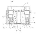
- the wastewater lifting plant shown by way of example has an upwardly open collecting container 2, which is preferably designed as a molded part made of plastic. At the top of the collecting container 2 is closed by a flange plate 4, which forms a lid for the collecting container 2.
- the flange plate 4 carries all the essential components of sewage lifting plant. Thus, it bears in particular a pump unit 6, with an above the flange plate 4 arranged electric motor 8 and arranged below the flange plate 4 pump 10.
- the pump 10 is arranged so that it dips into the interior of the collecting container 2 and its impeller as far down located in the interior of the collecting container 2.
- a float switch 12 is arranged on the flange plate 4, which serves for switching on and off of the pump unit 6.
- the float switch 12 has a float 14 arranged inside the collecting container 2, ie below the flange plate.
- the float 14 is connected by means of an actuating rod 16 with an electrical switch 18 located above the flange plate 4.
- the electrical switch 18 As the liquid level in the sump 2 rises, it floats the float 14 upwards and actuated via the actuating rod 16, the electrical switch 18 so that the electric motor 8 is turned on and driven by this, the pump 10, so that liquid is conveyed out of the sump to the outside.
- the float 14 drops down and actuates the electric switch 18 via the actuating rod 16 so that the electric motor 8 is switched off again.
- the flange plate 4 has at its four corners in each case a vertically downwardly extending inlet pipe 22.
- the inlet pipes 22 are in this case formed integrally with the flange plate 4 made of plastic.
- a seal 24 is used in each case, which serves to seal a connecting pipe 26 used.
- All four inlet pipes 22 are of identical design, and can optionally be used to connect a connecting pipe 26, depending on which direction the waste water is to be supplied to the collecting tank 2.
- the connecting pipe 26 is simply inserted from above into the inlet pipe 22 and sealingly comes into contact with the inner circumference of the seal 24. With its outer circumference, the seal 24 is sealingly against the inner circumference of the inlet pipe 22.
- the inlet pipes 22 are formed so long in the vertical direction X that their lower ends 28 in the vertical direction X of the flange plate 4 are spaced further than the lower end of the float 14. In this way it is achieved that when the flange plate 4 from taken from the sump 2 and placed on a flat surface, the flange plate 4 comes to rest with the attached components, in particular the float 14 and the pump 10 on the lower ends 28 of the inlet pipes 22 and the float 14 ideally not with the shelf in Contact is coming. This will be a damage the float 14 or connected to this via the actuating rod 16 electrical switch 18 when parking the flange plate 4 is prevented.
- the inlet pipes 22 are not open directly at their lower ends 28 but have radially directed outlet openings 30, which are each spaced from the lower end 28 vertically upwards. This ensures that the outlet openings, through which liquid or water flows into the collecting container 2, are not located directly at the bottom of the collecting container 2, so that they can not become clogged by contaminants accumulating on the bottom of the collecting container 2.
- the inlet pipes 22 have a transversely extending closed end wall 32, from which an annular foot member 34 extends vertically down to the lower end 28. The end wall 32 in each case closes off the flow path or channel in the interior of the inlet pipe 22 downwards.
- the inlet tubes 22 engage with their lower end and the lower end portion, in which the outlet openings 30 are located, each in an inlet chamber 36 a.
- the inlet bosses 36 are formed in the corners of the header tank 2 by partition walls 38 which extend vertically upward from the bottom of the header tank 2 and connect to the side walls of the header tank 2.
- the partitions 38 are integrally formed with the walls of the collecting container 2, preferably made of plastic.
- inlet chambers 36 are formed, which are open only upwards, wherein the upper end 40 of the inlet chambers 36 are located above the upper edge of the outlet openings 30 of the inlet pipes 22. In this way, a gas barrier is formed.
- the inlet chamber 36 first fills with liquid up to the upper edge 40.
- the liquid then flows into the remaining region of the collecting container 2, in which the float 14 and the pump 10 are arranged. This ensures that the outlet openings 30 of the inlet pipe are always in the liquid, so that no gas from the inlet pipe 22 can flow into the interior of the collecting container 2. If gas flows through the connecting pipe 26 into the inlet pipe 22, this can be done by a gas outlet opening 42, which is formed by a gap between the outer circumference of the seal 24 and the inner circumference of the inlet pipe 22 at its upper end.
- This embodiment of the gas barrier is particularly advantageous if the wastewater lifting plant, as provided in the sewage lifting plant shown, is used as a condensate lifting plant in a heating system.
- exhaust gas from the heating system flows through the connecting pipe 26 to the sump 2. Since this exhaust gas contains aggressive substances, the exhaust gas should not enter into the interior of the collecting container 2, which is prevented by the described gas barrier, which is formed by the partition wall 38. Instead, the exhaust gas is then discharged through the gas outlet opening 42 into the environment.
- the flange plate 4 next to the inlet pipes only small openings, namely an opening 44 through which the actuating rod 16 extends, and an opening 46 through which a shaft of the pump assembly extends from the electric motor 8 to the pump 10. Further, an opening 48 is provided, through which an outlet line, not shown here, may extend from the pump 10 to the outside. In addition, only mounting holes are still provided.
Landscapes
- Engineering & Computer Science (AREA)
- Health & Medical Sciences (AREA)
- Life Sciences & Earth Sciences (AREA)
- Hydrology & Water Resources (AREA)
- Public Health (AREA)
- Water Supply & Treatment (AREA)
- Structural Engineering (AREA)
- Environmental & Geological Engineering (AREA)
- Mechanical Engineering (AREA)
- General Engineering & Computer Science (AREA)
- Sewage (AREA)
- Structures Of Non-Positive Displacement Pumps (AREA)
Priority Applications (3)
| Application Number | Priority Date | Filing Date | Title |
|---|---|---|---|
| EP20110182391 EP2573288B1 (fr) | 2011-09-22 | 2011-09-22 | Installation de relèvement d'eaux usées |
| US13/624,426 US9243395B2 (en) | 2011-09-22 | 2012-09-21 | Waste water lifting installation |
| CN201210355585.XA CN103015521B (zh) | 2011-09-22 | 2012-09-21 | 废水提升装置 |
Applications Claiming Priority (1)
| Application Number | Priority Date | Filing Date | Title |
|---|---|---|---|
| EP20110182391 EP2573288B1 (fr) | 2011-09-22 | 2011-09-22 | Installation de relèvement d'eaux usées |
Publications (2)
| Publication Number | Publication Date |
|---|---|
| EP2573288A1 true EP2573288A1 (fr) | 2013-03-27 |
| EP2573288B1 EP2573288B1 (fr) | 2013-10-16 |
Family
ID=44651513
Family Applications (1)
| Application Number | Title | Priority Date | Filing Date |
|---|---|---|---|
| EP20110182391 Active EP2573288B1 (fr) | 2011-09-22 | 2011-09-22 | Installation de relèvement d'eaux usées |
Country Status (3)
| Country | Link |
|---|---|
| US (1) | US9243395B2 (fr) |
| EP (1) | EP2573288B1 (fr) |
| CN (1) | CN103015521B (fr) |
Cited By (1)
| Publication number | Priority date | Publication date | Assignee | Title |
|---|---|---|---|---|
| WO2017125294A1 (fr) * | 2016-01-22 | 2017-07-27 | Ksb Aktiengesellschaft | Dispositif de purge |
Families Citing this family (2)
| Publication number | Priority date | Publication date | Assignee | Title |
|---|---|---|---|---|
| TWM482715U (zh) * | 2014-03-31 | 2014-07-21 | Holimay Corp | 具有低噪音排水殼之空調設備排水裝置 |
| DE102018207243A1 (de) * | 2018-05-09 | 2019-11-14 | KSB SE & Co. KGaA | Abwasserhebeanlage |
Citations (2)
| Publication number | Priority date | Publication date | Assignee | Title |
|---|---|---|---|---|
| DE3113903A1 (de) * | 1981-04-07 | 1982-10-21 | Werner Dipl.-Ing. 2800 Bremen Fass | "vorrichtung zur vakuumabsaugung von fluessigkeiten" |
| US20060228222A1 (en) * | 2005-03-29 | 2006-10-12 | Pohler Donald M | Sewage handling system, cover, and controls |
Family Cites Families (8)
| Publication number | Priority date | Publication date | Assignee | Title |
|---|---|---|---|---|
| US5103793A (en) * | 1991-01-15 | 1992-04-14 | Brunswick Corporation | Vapor separator for an internal combustion engine |
| JP3751334B2 (ja) * | 1995-04-05 | 2006-03-01 | 株式会社鶴見製作所 | 廃水の排出装置 |
| US6322326B1 (en) * | 1999-01-29 | 2001-11-27 | Lee W. Davis | Modular condensate pump assembly |
| CN2396117Y (zh) * | 1999-11-01 | 2000-09-13 | 祝丹 | 密封式污水提升输送装置 |
| JP2002285635A (ja) * | 2001-03-24 | 2002-10-03 | Akiharu Enami | クッションタンクを備えた汚水吸引排出装置 |
| US20070224050A1 (en) * | 2006-03-24 | 2007-09-27 | Ward Charles B | Condensate pump |
| CN201850629U (zh) * | 2010-10-30 | 2011-06-01 | 中冶北方工程技术有限公司 | 抗沉淀污水排放装置 |
| CN201981644U (zh) * | 2011-02-11 | 2011-09-21 | 万若(北京)环境工程技术有限公司 | 真空二次提升装置 |
-
2011
- 2011-09-22 EP EP20110182391 patent/EP2573288B1/fr active Active
-
2012
- 2012-09-21 CN CN201210355585.XA patent/CN103015521B/zh not_active Expired - Fee Related
- 2012-09-21 US US13/624,426 patent/US9243395B2/en active Active
Patent Citations (2)
| Publication number | Priority date | Publication date | Assignee | Title |
|---|---|---|---|---|
| DE3113903A1 (de) * | 1981-04-07 | 1982-10-21 | Werner Dipl.-Ing. 2800 Bremen Fass | "vorrichtung zur vakuumabsaugung von fluessigkeiten" |
| US20060228222A1 (en) * | 2005-03-29 | 2006-10-12 | Pohler Donald M | Sewage handling system, cover, and controls |
Cited By (1)
| Publication number | Priority date | Publication date | Assignee | Title |
|---|---|---|---|---|
| WO2017125294A1 (fr) * | 2016-01-22 | 2017-07-27 | Ksb Aktiengesellschaft | Dispositif de purge |
Also Published As
| Publication number | Publication date |
|---|---|
| EP2573288B1 (fr) | 2013-10-16 |
| US20130074950A1 (en) | 2013-03-28 |
| CN103015521A (zh) | 2013-04-03 |
| CN103015521B (zh) | 2015-05-20 |
| US9243395B2 (en) | 2016-01-26 |
Similar Documents
| Publication | Publication Date | Title |
|---|---|---|
| DE102005031420A1 (de) | Kombinierte Tauch-/Flachabsaug-Rotationspumpe | |
| EP2573288B1 (fr) | Installation de relèvement d'eaux usées | |
| DE102010053588B4 (de) | Gärsaftabscheider | |
| EP3364043B1 (fr) | Groupe motopompe avec dispositif de purge d'air et de vidange intégré | |
| DE10252038B3 (de) | Geruchsverschluß | |
| DE10361532B3 (de) | Vorrichtung zum Verhindern des Wassereintritts in einen Abwasserschacht | |
| EP1127988B1 (fr) | Regard d'évacuation muni d'une fermeture à flotteur | |
| EP1775395B1 (fr) | Dispositif d'écoulement pour installations sanitaires | |
| DE102011107817A1 (de) | Einrichtung zum Abpumpen von Flüssigkeiten | |
| EP4417893A1 (fr) | Dispositif d'évacuation de condensat pour appareil de chauffage et appareil de chauffage | |
| WO2010022704A2 (fr) | Citerne pourvue d'un filtre à eau de pluie dans l'arrivée et boîtier de filtre pour filtre à eau de pluie | |
| DE102023123249A1 (de) | Anordnungssystem zur Anordnung eines Spülbehälters eines Sanitärausstattungsgegenstandes | |
| DE20105661U1 (de) | Kleinkläranlage | |
| EP2154300B1 (fr) | Station d'eaux usées | |
| DE202008015411U1 (de) | Kondensatauffangbehälter | |
| EP2106731B1 (fr) | Lave-vaisselle | |
| EP2573284B1 (fr) | Installation de relèvement d'eaux usées | |
| EP2776640B1 (fr) | Dispositif formant siphon de sol | |
| DE202004007793U1 (de) | Geruchverschluss für Seiteneinläufe | |
| DE29723263U1 (de) | Sammelanlage für Wasser | |
| DE102010038298A1 (de) | Abscheider, insbesondere Fettabscheider | |
| EP3421676B1 (fr) | Élément de siphon à installer dans un écoulement, en particulier dans un écoulement d'un urinoir sans eau | |
| DE102010026424A1 (de) | Straßenentwässerung (Gulli) | |
| DE102010006801A1 (de) | Dachentwässerung (roof drain) | |
| EP4520887A1 (fr) | Bouche d'égout avec piège à odeurs |
Legal Events
| Date | Code | Title | Description |
|---|---|---|---|
| PUAI | Public reference made under article 153(3) epc to a published international application that has entered the european phase |
Free format text: ORIGINAL CODE: 0009012 |
|
| AK | Designated contracting states |
Kind code of ref document: A1 Designated state(s): AL AT BE BG CH CY CZ DE DK EE ES FI FR GB GR HR HU IE IS IT LI LT LU LV MC MK MT NL NO PL PT RO RS SE SI SK SM TR |
|
| AX | Request for extension of the european patent |
Extension state: BA ME |
|
| 17P | Request for examination filed |
Effective date: 20130315 |
|
| GRAP | Despatch of communication of intention to grant a patent |
Free format text: ORIGINAL CODE: EPIDOSNIGR1 |
|
| RIC1 | Information provided on ipc code assigned before grant |
Ipc: E03F 5/22 20060101AFI20130408BHEP |
|
| INTG | Intention to grant announced |
Effective date: 20130502 |
|
| GRAS | Grant fee paid |
Free format text: ORIGINAL CODE: EPIDOSNIGR3 |
|
| GRAA | (expected) grant |
Free format text: ORIGINAL CODE: 0009210 |
|
| AK | Designated contracting states |
Kind code of ref document: B1 Designated state(s): AL AT BE BG CH CY CZ DE DK EE ES FI FR GB GR HR HU IE IS IT LI LT LU LV MC MK MT NL NO PL PT RO RS SE SI SK SM TR |
|
| REG | Reference to a national code |
Ref country code: GB Ref legal event code: FG4D Free format text: NOT ENGLISH |
|
| REG | Reference to a national code |
Ref country code: CH Ref legal event code: EP |
|
| REG | Reference to a national code |
Ref country code: IE Ref legal event code: FG4D Free format text: LANGUAGE OF EP DOCUMENT: GERMAN |
|
| REG | Reference to a national code |
Ref country code: AT Ref legal event code: REF Ref document number: 636603 Country of ref document: AT Kind code of ref document: T Effective date: 20131115 |
|
| REG | Reference to a national code |
Ref country code: DE Ref legal event code: R096 Ref document number: 502011001488 Country of ref document: DE Effective date: 20131212 |
|
| REG | Reference to a national code |
Ref country code: NL Ref legal event code: VDEP Effective date: 20131016 |
|
| REG | Reference to a national code |
Ref country code: LT Ref legal event code: MG4D |
|
| PG25 | Lapsed in a contracting state [announced via postgrant information from national office to epo] |
Ref country code: FI Free format text: LAPSE BECAUSE OF FAILURE TO SUBMIT A TRANSLATION OF THE DESCRIPTION OR TO PAY THE FEE WITHIN THE PRESCRIBED TIME-LIMIT Effective date: 20131016 Ref country code: NL Free format text: LAPSE BECAUSE OF FAILURE TO SUBMIT A TRANSLATION OF THE DESCRIPTION OR TO PAY THE FEE WITHIN THE PRESCRIBED TIME-LIMIT Effective date: 20131016 Ref country code: HR Free format text: LAPSE BECAUSE OF FAILURE TO SUBMIT A TRANSLATION OF THE DESCRIPTION OR TO PAY THE FEE WITHIN THE PRESCRIBED TIME-LIMIT Effective date: 20131016 Ref country code: LT Free format text: LAPSE BECAUSE OF FAILURE TO SUBMIT A TRANSLATION OF THE DESCRIPTION OR TO PAY THE FEE WITHIN THE PRESCRIBED TIME-LIMIT Effective date: 20131016 Ref country code: NO Free format text: LAPSE BECAUSE OF FAILURE TO SUBMIT A TRANSLATION OF THE DESCRIPTION OR TO PAY THE FEE WITHIN THE PRESCRIBED TIME-LIMIT Effective date: 20140116 Ref country code: SE Free format text: LAPSE BECAUSE OF FAILURE TO SUBMIT A TRANSLATION OF THE DESCRIPTION OR TO PAY THE FEE WITHIN THE PRESCRIBED TIME-LIMIT Effective date: 20131016 Ref country code: IS Free format text: LAPSE BECAUSE OF FAILURE TO SUBMIT A TRANSLATION OF THE DESCRIPTION OR TO PAY THE FEE WITHIN THE PRESCRIBED TIME-LIMIT Effective date: 20140216 |
|
| PG25 | Lapsed in a contracting state [announced via postgrant information from national office to epo] |
Ref country code: RS Free format text: LAPSE BECAUSE OF FAILURE TO SUBMIT A TRANSLATION OF THE DESCRIPTION OR TO PAY THE FEE WITHIN THE PRESCRIBED TIME-LIMIT Effective date: 20131016 Ref country code: LV Free format text: LAPSE BECAUSE OF FAILURE TO SUBMIT A TRANSLATION OF THE DESCRIPTION OR TO PAY THE FEE WITHIN THE PRESCRIBED TIME-LIMIT Effective date: 20131016 Ref country code: ES Free format text: LAPSE BECAUSE OF FAILURE TO SUBMIT A TRANSLATION OF THE DESCRIPTION OR TO PAY THE FEE WITHIN THE PRESCRIBED TIME-LIMIT Effective date: 20131016 Ref country code: CY Free format text: LAPSE BECAUSE OF FAILURE TO SUBMIT A TRANSLATION OF THE DESCRIPTION OR TO PAY THE FEE WITHIN THE PRESCRIBED TIME-LIMIT Effective date: 20131016 |
|
| PG25 | Lapsed in a contracting state [announced via postgrant information from national office to epo] |
Ref country code: PT Free format text: LAPSE BECAUSE OF FAILURE TO SUBMIT A TRANSLATION OF THE DESCRIPTION OR TO PAY THE FEE WITHIN THE PRESCRIBED TIME-LIMIT Effective date: 20140217 |
|
| REG | Reference to a national code |
Ref country code: DE Ref legal event code: R097 Ref document number: 502011001488 Country of ref document: DE |
|
| PG25 | Lapsed in a contracting state [announced via postgrant information from national office to epo] |
Ref country code: EE Free format text: LAPSE BECAUSE OF FAILURE TO SUBMIT A TRANSLATION OF THE DESCRIPTION OR TO PAY THE FEE WITHIN THE PRESCRIBED TIME-LIMIT Effective date: 20131016 |
|
| PLBE | No opposition filed within time limit |
Free format text: ORIGINAL CODE: 0009261 |
|
| STAA | Information on the status of an ep patent application or granted ep patent |
Free format text: STATUS: NO OPPOSITION FILED WITHIN TIME LIMIT |
|
| PG25 | Lapsed in a contracting state [announced via postgrant information from national office to epo] |
Ref country code: PL Free format text: LAPSE BECAUSE OF FAILURE TO SUBMIT A TRANSLATION OF THE DESCRIPTION OR TO PAY THE FEE WITHIN THE PRESCRIBED TIME-LIMIT Effective date: 20131016 Ref country code: RO Free format text: LAPSE BECAUSE OF FAILURE TO SUBMIT A TRANSLATION OF THE DESCRIPTION OR TO PAY THE FEE WITHIN THE PRESCRIBED TIME-LIMIT Effective date: 20131016 Ref country code: IT Free format text: LAPSE BECAUSE OF FAILURE TO SUBMIT A TRANSLATION OF THE DESCRIPTION OR TO PAY THE FEE WITHIN THE PRESCRIBED TIME-LIMIT Effective date: 20131016 Ref country code: CZ Free format text: LAPSE BECAUSE OF FAILURE TO SUBMIT A TRANSLATION OF THE DESCRIPTION OR TO PAY THE FEE WITHIN THE PRESCRIBED TIME-LIMIT Effective date: 20131016 Ref country code: SK Free format text: LAPSE BECAUSE OF FAILURE TO SUBMIT A TRANSLATION OF THE DESCRIPTION OR TO PAY THE FEE WITHIN THE PRESCRIBED TIME-LIMIT Effective date: 20131016 |
|
| 26N | No opposition filed |
Effective date: 20140717 |
|
| PG25 | Lapsed in a contracting state [announced via postgrant information from national office to epo] |
Ref country code: DK Free format text: LAPSE BECAUSE OF FAILURE TO SUBMIT A TRANSLATION OF THE DESCRIPTION OR TO PAY THE FEE WITHIN THE PRESCRIBED TIME-LIMIT Effective date: 20131016 |
|
| REG | Reference to a national code |
Ref country code: DE Ref legal event code: R097 Ref document number: 502011001488 Country of ref document: DE Effective date: 20140717 |
|
| PG25 | Lapsed in a contracting state [announced via postgrant information from national office to epo] |
Ref country code: SI Free format text: LAPSE BECAUSE OF FAILURE TO SUBMIT A TRANSLATION OF THE DESCRIPTION OR TO PAY THE FEE WITHIN THE PRESCRIBED TIME-LIMIT Effective date: 20131016 |
|
| PG25 | Lapsed in a contracting state [announced via postgrant information from national office to epo] |
Ref country code: MC Free format text: LAPSE BECAUSE OF FAILURE TO SUBMIT A TRANSLATION OF THE DESCRIPTION OR TO PAY THE FEE WITHIN THE PRESCRIBED TIME-LIMIT Effective date: 20131016 Ref country code: LU Free format text: LAPSE BECAUSE OF FAILURE TO SUBMIT A TRANSLATION OF THE DESCRIPTION OR TO PAY THE FEE WITHIN THE PRESCRIBED TIME-LIMIT Effective date: 20140922 |
|
| REG | Reference to a national code |
Ref country code: CH Ref legal event code: PL |
|
| REG | Reference to a national code |
Ref country code: IE Ref legal event code: MM4A |
|
| PG25 | Lapsed in a contracting state [announced via postgrant information from national office to epo] |
Ref country code: BE Free format text: LAPSE BECAUSE OF NON-PAYMENT OF DUE FEES Effective date: 20140930 |
|
| PG25 | Lapsed in a contracting state [announced via postgrant information from national office to epo] |
Ref country code: LI Free format text: LAPSE BECAUSE OF NON-PAYMENT OF DUE FEES Effective date: 20140930 Ref country code: CH Free format text: LAPSE BECAUSE OF NON-PAYMENT OF DUE FEES Effective date: 20140930 |
|
| PG25 | Lapsed in a contracting state [announced via postgrant information from national office to epo] |
Ref country code: IE Free format text: LAPSE BECAUSE OF NON-PAYMENT OF DUE FEES Effective date: 20140922 |
|
| PG25 | Lapsed in a contracting state [announced via postgrant information from national office to epo] |
Ref country code: SM Free format text: LAPSE BECAUSE OF FAILURE TO SUBMIT A TRANSLATION OF THE DESCRIPTION OR TO PAY THE FEE WITHIN THE PRESCRIBED TIME-LIMIT Effective date: 20131016 |
|
| PG25 | Lapsed in a contracting state [announced via postgrant information from national office to epo] |
Ref country code: GR Free format text: LAPSE BECAUSE OF FAILURE TO SUBMIT A TRANSLATION OF THE DESCRIPTION OR TO PAY THE FEE WITHIN THE PRESCRIBED TIME-LIMIT Effective date: 20140117 Ref country code: BG Free format text: LAPSE BECAUSE OF FAILURE TO SUBMIT A TRANSLATION OF THE DESCRIPTION OR TO PAY THE FEE WITHIN THE PRESCRIBED TIME-LIMIT Effective date: 20131016 Ref country code: MT Free format text: LAPSE BECAUSE OF FAILURE TO SUBMIT A TRANSLATION OF THE DESCRIPTION OR TO PAY THE FEE WITHIN THE PRESCRIBED TIME-LIMIT Effective date: 20131016 |
|
| REG | Reference to a national code |
Ref country code: FR Ref legal event code: PLFP Year of fee payment: 6 |
|
| PG25 | Lapsed in a contracting state [announced via postgrant information from national office to epo] |
Ref country code: TR Free format text: LAPSE BECAUSE OF FAILURE TO SUBMIT A TRANSLATION OF THE DESCRIPTION OR TO PAY THE FEE WITHIN THE PRESCRIBED TIME-LIMIT Effective date: 20131016 Ref country code: HU Free format text: LAPSE BECAUSE OF FAILURE TO SUBMIT A TRANSLATION OF THE DESCRIPTION OR TO PAY THE FEE WITHIN THE PRESCRIBED TIME-LIMIT; INVALID AB INITIO Effective date: 20110922 |
|
| REG | Reference to a national code |
Ref country code: FR Ref legal event code: PLFP Year of fee payment: 7 |
|
| REG | Reference to a national code |
Ref country code: AT Ref legal event code: MM01 Ref document number: 636603 Country of ref document: AT Kind code of ref document: T Effective date: 20160922 |
|
| PG25 | Lapsed in a contracting state [announced via postgrant information from national office to epo] |
Ref country code: AT Free format text: LAPSE BECAUSE OF NON-PAYMENT OF DUE FEES Effective date: 20160922 |
|
| PG25 | Lapsed in a contracting state [announced via postgrant information from national office to epo] |
Ref country code: MK Free format text: LAPSE BECAUSE OF FAILURE TO SUBMIT A TRANSLATION OF THE DESCRIPTION OR TO PAY THE FEE WITHIN THE PRESCRIBED TIME-LIMIT Effective date: 20131016 |
|
| REG | Reference to a national code |
Ref country code: FR Ref legal event code: PLFP Year of fee payment: 8 |
|
| PG25 | Lapsed in a contracting state [announced via postgrant information from national office to epo] |
Ref country code: AL Free format text: LAPSE BECAUSE OF FAILURE TO SUBMIT A TRANSLATION OF THE DESCRIPTION OR TO PAY THE FEE WITHIN THE PRESCRIBED TIME-LIMIT Effective date: 20131016 |
|
| REG | Reference to a national code |
Ref country code: DE Ref legal event code: R082 Ref document number: 502011001488 Country of ref document: DE |
|
| PGFP | Annual fee paid to national office [announced via postgrant information from national office to epo] |
Ref country code: DE Payment date: 20250919 Year of fee payment: 15 |
|
| PGFP | Annual fee paid to national office [announced via postgrant information from national office to epo] |
Ref country code: GB Payment date: 20250918 Year of fee payment: 15 |
|
| PGFP | Annual fee paid to national office [announced via postgrant information from national office to epo] |
Ref country code: FR Payment date: 20250922 Year of fee payment: 15 |