EP2573302A2 - Dispositif de protection à particules - Google Patents
Dispositif de protection à particules Download PDFInfo
- Publication number
- EP2573302A2 EP2573302A2 EP12005741A EP12005741A EP2573302A2 EP 2573302 A2 EP2573302 A2 EP 2573302A2 EP 12005741 A EP12005741 A EP 12005741A EP 12005741 A EP12005741 A EP 12005741A EP 2573302 A2 EP2573302 A2 EP 2573302A2
- Authority
- EP
- European Patent Office
- Prior art keywords
- frame
- hinge
- protection device
- clamping frame
- particle protection
- Prior art date
- Legal status (The legal status is an assumption and is not a legal conclusion. Google has not performed a legal analysis and makes no representation as to the accuracy of the status listed.)
- Withdrawn
Links
Images



Classifications
-
- E—FIXED CONSTRUCTIONS
- E05—LOCKS; KEYS; WINDOW OR DOOR FITTINGS; SAFES
- E05F—DEVICES FOR MOVING WINGS INTO OPEN OR CLOSED POSITION; CHECKS FOR WINGS; WING FITTINGS NOT OTHERWISE PROVIDED FOR, CONCERNED WITH THE FUNCTIONING OF THE WING
- E05F1/00—Closers or openers for wings, not otherwise provided for in this subclass
- E05F1/08—Closers or openers for wings, not otherwise provided for in this subclass spring-actuated, e.g. for horizontally sliding wings
- E05F1/10—Closers or openers for wings, not otherwise provided for in this subclass spring-actuated, e.g. for horizontally sliding wings for swinging wings, e.g. counterbalance
- E05F1/12—Mechanisms in the shape of hinges or pivots, operated by springs
- E05F1/1207—Mechanisms in the shape of hinges or pivots, operated by springs with a coil spring parallel with the pivot axis
-
- E—FIXED CONSTRUCTIONS
- E05—LOCKS; KEYS; WINDOW OR DOOR FITTINGS; SAFES
- E05D—HINGES OR SUSPENSION DEVICES FOR DOORS, WINDOWS OR WINGS
- E05D11/00—Additional features or accessories of hinges
- E05D11/10—Devices for preventing movement between relatively-movable hinge parts
- E05D11/1014—Devices for preventing movement between relatively-movable hinge parts for maintaining the hinge in only one position, e.g. closed
-
- E—FIXED CONSTRUCTIONS
- E05—LOCKS; KEYS; WINDOW OR DOOR FITTINGS; SAFES
- E05D—HINGES OR SUSPENSION DEVICES FOR DOORS, WINDOWS OR WINGS
- E05D5/00—Construction of single parts, e.g. the parts for attachment
- E05D5/02—Parts for attachment, e.g. flaps
- E05D5/0215—Parts for attachment, e.g. flaps for attachment to profile members or the like
- E05D5/0223—Parts for attachment, e.g. flaps for attachment to profile members or the like with parts, e.g. screws, extending through the profile wall or engaging profile grooves
- E05D5/0238—Parts for attachment, e.g. flaps for attachment to profile members or the like with parts, e.g. screws, extending through the profile wall or engaging profile grooves with parts engaging profile grooves
-
- E—FIXED CONSTRUCTIONS
- E05—LOCKS; KEYS; WINDOW OR DOOR FITTINGS; SAFES
- E05Y—INDEXING SCHEME ASSOCIATED WITH SUBCLASSES E05D AND E05F, RELATING TO CONSTRUCTION ELEMENTS, ELECTRIC CONTROL, POWER SUPPLY, POWER SIGNAL OR TRANSMISSION, USER INTERFACES, MOUNTING OR COUPLING, DETAILS, ACCESSORIES, AUXILIARY OPERATIONS NOT OTHERWISE PROVIDED FOR, APPLICATION THEREOF
- E05Y2900/00—Application of doors, windows, wings or fittings thereof
- E05Y2900/10—Application of doors, windows, wings or fittings thereof for buildings or parts thereof
- E05Y2900/13—Type of wing
- E05Y2900/132—Doors
- E05Y2900/136—Screens; Insect doors
Definitions
- the invention relates to a particle protection device with a clamping frame, wherein particle protection device is understood in particular an insect or pollen protection device.
- serve particle protection device which include a tenter frame with a mounted thereon particle guard.
- the clamping frame covers the door opening as completely as possible.
- a closing spring for independently closing the clamping frame, by means of screws or nails on the frame be attached.
- the object of the invention is to provide a particle protection device improved, in particular with regard to the hinge.
- the particle protection device comprises a tensioning frame, wherein the term particle protection device is understood to mean in particular an insect protection or pollen protection device.
- the clamping frame is provided and furnished, for example, to cover a door or window frame.
- the tensioning frame comprises a protective grid, in particular a pollen protection or insect screen.
- the particle protection device also comprises at least one hinge, in particular two or three hinges, by means of which the clamping frame can be mounted on one side directly rotatably on a door frame or window frame or indirectly to a frame-like support frame, which in turn attached to the door frame or the window frame can be. In this way it is possible to spend the clamping frame substantially completely from the space surrounded by the frame or the support frame.
- the clamping frame preferably comprises hollow profiles made of aluminum or a plastic and consists in particular of these or a combination of these with connecting elements, such as corner connectors, and a closing device.
- the support frame is preferably composed of hollow sections of aluminum or a plastic, possibly by means of corner connectors.
- the hinge comprises a first hinge band which is connected to the frame or the support frame, and a second hinge strap which is connected to the clamping frame. Furthermore, the hinge has a closing spring.
- the closing spring of the clamping frame is moved in the absence of further forces acting on the clamping frame forces in a closed position. Under closed Position here is understood in particular that the space surrounded by the frame or the support frame is substantially filled by means of the clamping frame so that no particles can pass through this gap. In this way, an unintentional stay open of the tenter frame and a behind the gap space of a building is prevented from being contaminated by any particles.
- the hinge has a locking device, by means of which the clamping frame is held in a position with respect to the frame or with respect to the support frame.
- the locking device is actuated and the clamping frame is in position, the clamping frame is not moved in spite of the closing spring.
- the locking device is manually operated, for example, by a user. Conveniently, this is on the hinge, a lever by means of which the movement of the clamping frame is prevented.
- each time when the clamping frame is in the position the locking device triggered independently.
- the tenter is moved to the position, it is held there by means of the locking device.
- the locking device For further pivoting, therefore, the locking device must be solved.
- the force exerted by the closing spring on the clamping frame adjustable.
- the hinge can be adjusted to different environmental conditions and differently designed clamping frames, without the one hand, the force required to open the clamping frame, comparatively large and the clamping frame is difficult to open.
- it can be prevented that the swing frame remains due to frictional effects or, for example, a draft in an undesirable position or spent there.
- the adjustment of the force is suitably stepwise preferably by means of a latching nose, which is spent in recesses and fixed there each. Each recess corresponds to a certain force.
- the closing spring is for Example on the one hand connected to the locking lug and on the other hand held stationary and is thus stretched or relaxed at a Spend the detent.
- the position corresponds to an angle between the clamping frame and the frame or the support frame of substantially 0 °.
- the clamping frame is then locked when the clamping frame rests against the frame or the support frame and thus the particle protection device is in the closed state.
- the tenter is held in the closed position, for example, in a gust of wind and particles can not get into the space behind the particle protection device during this time.
- the clamping frame is held by means of the locking device in a position in which the particle protection device is open.
- the angle between the clamping frame and the frame or the support frame is greater than 0 ° and in particular 45 ° or 90 °.
- the swing frame is held open by the locking device automatically. If the pivoting frame is opened further than the angle corresponding to the locked position, when the pivoting frame is released it is pivoted by means of the closing spring and the angle between the pivoting frame and the frame or the supporting frame is consequently reduced until the angle corresponds to the locked position.
- the clamping frame is locked at both 0 ° and at least one further angle, which is in particular 45 ° or 90 °.
- the locking device comprises a pressure pin with a compression spring which is suitably a screw or leaf spring.
- the compression spring is arranged such that it exerts a pressure on an engagement element.
- the spring-loaded engaging element serves to lock the clamping frame.
- the pressure pin is arranged on the second hinge band and is moved with a pivoting of the clamping frame with this with respect to the frame or the support frame.
- the force exerted by the compression spring on the engagement element adjustable.
- the adjustment is particularly continuous. In this way it is possible to adjust the force required to move the clamping frame out of the locked position and adapt it to current conditions.
- the compression spring is the closing spring. This thus fulfills a dual function. In this way, the number of components that make up the particle protection device can be kept low, resulting in a comparatively inexpensive production of the particle protection device.
- the engagement element is designed capsule-shaped and consists in particular of a metal.
- capsule-shaped means that the engagement element has a cylindrical first body and a hemispherical second body, which are connected to one another, in particular in one piece.
- the radius of the cylinder and that of the ball are substantially equal and the cylinder is attached to the hemisphere so that the edges are in line with each other.
- the center of one of the base surfaces of the cylinder is thus located substantially in the same place as the center of the circular surface of the hemisphere.
- the engagement element is moved along a receiving groove during pivoting of the clamping frame, wherein the spherical portion of the engaging element is located in particular within the receiving groove.
- the pressure pin having the engaging element is arranged on the second hinge band, and the receiving groove is designed to be substantially stationary and circular arc-shaped. Within the receiving groove a detent recess is introduced.
- the engaging member is moved out of the detent recess against the force of the compression spring out of the detent recess and the tenter is further pivoted with respect to the frame.
- the clamping frame is locked, and acts on this a comparatively large force, the engagement element released from the detent recess, and the clamping frame can be pivoted either with the force acting or by means of the closing spring.
- the first hinge strap comprises a locking cone, in which the receiving groove is introduced.
- the locking cone has, for example, the shape of a segment of a cone or a truncated cone.
- the receiving groove is in this case preferably introduced into the base surface or into the larger of the two base surfaces of the locking cone, wherein this base surface in particular extends substantially horizontally and is the lowermost portion of the locking cone. If the hinge is used outdoors, so in this way the receiving groove from contamination or contamination, such as rainwater, protected. Therefore, the functionality of the hinge is relatively unsusceptible to external weather conditions.
- the engaging element is designed mushroom-shaped.
- Mushroom-shaped is understood to mean that the engagement element has a cylindrical basic body to which a spherical segment adjoins. The radius of the circular surface of the spherical segment is greater than the radius of the cylinder, wherein the respective centers are located substantially at the same location.
- the engaging element is made in one piece from a plastic.
- the compression spring is connected in particular to the cylindrical base body of the engaging element and is advantageously in contact with it.
- the ball segment is influenced by means of a further element of the locking device such that the clamping frame is locked in position.
- the first hinge strap comprises a retaining lug which restrains the engagement element and thus locks the tenter in position.
- the retaining lug expediently extends substantially perpendicular to the pressure pin.
- the pressure pin is attached to the engagement element on the second hinge strap.
- the clamping frame can be pivoted by means of the closing spring in a new position, wherein the compression spring returns the engaging element in its original position.
- first hinge band, the second hinge band or each hinge band has a sliding block-like retaining element.
- the holding element is arranged within a longitudinal groove of the clamping frame or the frame-side support frame.
- the cross-section of the retaining element is substantially T-shaped, with the horizontal or transverse leg being within the groove and being at least partially enclosed by its boundary, while the vertical or longitudinal leg protrudes from the groove.
- the longitudinal groove is expediently an already existing functional chamber which can receive or receive a sealing brush.
- the sealing brush is removed from the region of the groove, within which the holding element is located. The sealing brush serves to seal the gap between the clamping frame and the frame or the support frame. In this way, penetration of particles through the particle protection device is effectively prevented.
- the retaining element When mounting the hinge, the retaining element is inserted into the longitudinal groove and moved to the desired location on the clamping frame or the support frame. If the hinge is in place, it will be fixed there. This is done for example by means of a further device or due to a frictional connection between the holding element and the groove. For this purpose, in particular the friction between the holding element and this at least partially surrounding boundary of the groove is comparatively large.
- the first hinge band can be connected by means of an adhesive strip on the frame or on the support frame.
- the adhesive strip is in particular double-sided adhesive and is arranged during assembly of the hinge between the hinge strap and the frame or the support frame.
- the first hinge is self-adhesive.
- the first hinge strip is the frame side coated with an adhesive which is covered with a film. To install the hinge, the foil is removed and the hinge is attached to the frame or support frame at a suitable location with the first hinge.
- a further embodiment of the invention provides that the first hinge strap is clamped to the frame by means of a clamping device.
- the clamping device has, for example, a section with a U-shaped cross-section, which is slipped over a portion of the frame or of the support frame, wherein the two substantially parallel legs of the section directly or indirectly, for example via spacers, frictionally on the frame or abut the support frame.
- the clamping device comprises an eccentric adjusting mechanism, by means of which a gap located between the clamping frame and the frame or the supporting frame is adjusted.
- an eccentric adjusting mechanism by means of which a gap located between the clamping frame and the frame or the supporting frame is adjusted. In this way it is possible to adjust the orientation and position of the clamping frame and to avoid any loops of the clamping frame or parts of this on the frame or on the support frame or the environment or other bindings and eliminate.
- a particle protection device 2 is shown in perspective, which is designed as insect protection, and having a clamping frame 4.
- the clamping frame 4 comprises a number of horizontal and vertical profile strips or hollow profile strips 6 made of aluminum or plastic, which are connected in the corner regions by means (not visible) corner connectors. Furthermore, the clamping frame 4 comprises a horizontally extending transverse strut for stabilization. In this way, two surfaces 8 are formed by the profile strips 6, which are covered by a protective grid 10.
- the protective grid 10 fills each of the two surfaces 8 completely.
- either only one protective grid 10 can be used, which extends over the transverse strut, or in each area 8 is in each case a protective grid 10th arranged.
- the protective grid 10 is fastened to the profiled strips 6 by means of a hook-and-loop fastener or a welt, and prevents insects from penetrating through the surface 8.
- the protective grid 10 preferably consists of a fiberglass fabric with a mesh width which is less than 2 mm.
- the particle protection device 2 is inserted into a building opening, wherein the clamping frame 4 fulfills the function of a fly screen door in this example. It is also conceivable that by means of the particle protection device 2, a window opening is covered, or that by means of the particle protection device 2 penetration of pollen is prevented in the building.
- the protective grid 10 is a pollen protection grid (foil, fabric, cloth or the like). Furthermore, with a suitable choice of the protective grid 10 by means of the particle protection device 2, a darkening or a comparatively slight heating of a room to which the building opening leads can be effected.
- the particle protection device 2 has a frame-like support frame 12, which can be clamp-fixed within the building opening.
- the support frame 12 comprises a transverse profile strip 14 and two vertical longitudinal profile strips 15 connected thereto, wherein the construction and the materials of the support frame 12 essentially correspond to those of the clamping frame 4.
- the clamping frame 4 is connected to the support frame 12 by means of three hinges 16.
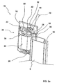
- each perspective view of a first embodiment of the hinge 16 is shown.
- the hinge 16 has a first hinge 18, which is fastened by means of two screws 20 on the support frame 12 or on a door or Novaz.
- two holes 22 are introduced with lowering recesses for the heads of the screws 20 in the second hinge 18.
- the hinge 16 includes a second hinge 24 having a support member 26 having a T-shaped cross-section.
- the holding element 26 acts as a sliding block and is located in a longitudinal groove 28 of the profile strips 6 of the clamping frame 4 a.
- the Longitudinal groove 28 serves as a functional chamber 30, in which a sealing brush, not shown here, can be introduced.
- the clamping frame 4 has a further functional chamber 30, within which the protective grid 10 is fastened by means of a welt.
- the first hinge 18 and the second hinge 24 are connected by a pin 32 such that the two hinge bands 18, 24 can be pivoted against each other.
- the pin 32 has a closing spring 34.
- One spring end of the closing spring 34 is mechanically connected to the first hinge band 18 and the other spring end is connected to the second hinge 24
- the two spring ends of the closing spring 34 are twisted and tensioned Force that puts the insect screen door in a closed position again.
- the hinge 16 has a locking device 38.
- the locking device 38 comprises a pressure pin 40 mounted in a cylindrical recess of the second hinge strap 24 with an engagement element 42.
- the engagement element 42 is mushroom-shaped and a thread 44 adjoins the lower end thereof upon which an adjustment element 46 is seated.
- a retaining lug 50 which is attached to the first hinge 18, is in contact with the engagement member 42 and inhibits its movement perpendicular to the longitudinal direction of the pressure pin 40.
- the engagement element 42 pressed due to the mushroom-shaped configuration of the retaining lug 50 on the second hinge band 24 out.
- the compression spring 48 is compressed.
- the closing spring 34 is tensioned. If the swing frame 4 is opened more than 45 ° with respect to the support frame 12, the retaining lug 50 no longer acts on the push pin 40 and the engagement member 42 is returned to its original position with respect to the second hinge band 24 by the compression spring 48.
- the closing spring 34 causes the swing frame 4 to pivot on the support frame 12 and the engagement member 42 moves toward the retention lug 50.
- the engaging member 42 abuts against the retaining lug 50 and is retained by this, which prevents the closing movement of the swing frame 4.
- the clamping frame 4 is thus held in an open position due to the locking device 38.
- the engagement element 42 among other things because of the mushroom-shaped configuration, against the force of the compression spring 48 moves to the second hinge 24, which is why the swing frame 4 is moved by means of the closing spring 34 in a closed position.
- the engaging element 42 is moved by means of the compression spring 48 in its original position with respect to the second hinge strap 24, where the swing frame 4 is locked by means of the retaining lug 50 and the pressure pin 40.
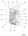
- hinge 16 is the in Fig. 3 shown embodiment of the hinge 16, in which the second hinge strap 24 is partially not shown, attached by means of two adhesive strips 52 on the support frame 12.
- the adhesive strips 52 are mounted on the support frame 12 facing side of the first hinge strap 18. Likewise, this could be entire side of the first hinge strap 18 to be executed completely self-adhesive.
- an adjusting member 54 is attached, by means of which the force exerted by the closing spring 34 on the clamping frame 4, can be adjusted.
- the tension of the closing spring 34 is changed, of which a spring end is in contact with the adjusting element 54.
- the adjustment member 54 has a latching lug 56 which engages in one of three recesses 58 shown and the position of the adjustment 54 locked with respect to the pin 32.
- Fig. 4 shows a further embodiment of the hinge 16, wherein the first hinge strap 18 has a sliding block-like holding element 60 having a substantially T-shaped cross-section.
- a longitudinal groove 62 is introduced, within which the holding element 60 rests. There, the holding element 60 and thus the hinge 16 can be displaced along the longitudinal groove 62 and fixed in a desired position.
- Fig. 5 is a further attachment of the hinge 16 shown in dashed lines support frame 12 by means of a clamping device 64 shown.
- the first hinge 18 is attached to an L-shaped first bracket 66 by means of two screws 68.
- the first carrier 66 is screwed by means of an adjusting or eccentric screw 70 with a second carrier 72 such that their common cross-section is substantially U-shaped.
- a clamping jaw 74 which bears against the support frame 12, is attached to the second support 72 with a number of alignment gaps 76, wherein the second support 72 rests in one of these adjustment gaps 76.
- this adjusting gap 76 it is possible, the distance between the jaw 74 and the first carrier 66 to adapt to the support frame 12 such that at this the hinge 16 is clamped.
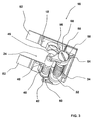
- FIG. 6 Another embodiment of the hinge 16 is in perspective in FIG Fig. 6 and in a soffit in Fig. 7 shown.
- the first hinge 18 has a locking cone 78, in the bottom of an arcuate receiving groove 80 is introduced, whose cross section is substantially semicircular.
- the capsule-shaped engagement element 42 slides along the receiving groove 80, which has a number of locking recesses 82.
- Under capsule-shaped is understood a cylindrical shape with a substantially hemispherical extension on the base or top surface.
- the engagement element 42 passes over one of the latching recesses 82, then this is pressed into the latching recess 82 by means of the compression spring 48. Only when exerting an increased force on the clamping frame 4 in the direction of the support frame 12, the engagement member 42 is released due to the rounded surface against the force of the compression spring 48 from the detent recess 82, and the clamping frame 4 can be further pivoted.
- the locking takes place when the clamping frame 4 with the frame forms an angle of substantially 90 ° and 0 °.
- a locking can also take place in a different pivot angle, preferably of 45 °, as a result of a latching of the engagement element 42 into a detent well 82 correspondingly positioned in the receiving groove 80.
Landscapes
- Engineering & Computer Science (AREA)
- Mechanical Engineering (AREA)
- Clamps And Clips (AREA)
Applications Claiming Priority (1)
| Application Number | Priority Date | Filing Date | Title |
|---|---|---|---|
| DE201110113983 DE102011113983A1 (de) | 2011-09-21 | 2011-09-21 | Partikelschutzvorrichtung |
Publications (1)
| Publication Number | Publication Date |
|---|---|
| EP2573302A2 true EP2573302A2 (fr) | 2013-03-27 |
Family
ID=46963352
Family Applications (1)
| Application Number | Title | Priority Date | Filing Date |
|---|---|---|---|
| EP12005741A Withdrawn EP2573302A2 (fr) | 2011-09-21 | 2012-08-08 | Dispositif de protection à particules |
Country Status (2)
| Country | Link |
|---|---|
| EP (1) | EP2573302A2 (fr) |
| DE (1) | DE102011113983A1 (fr) |
Cited By (1)
| Publication number | Priority date | Publication date | Assignee | Title |
|---|---|---|---|---|
| AT14290U1 (de) * | 2013-12-02 | 2015-07-15 | Trevision Gross Bild Technik Gmbh | Spannrahmen |
Family Cites Families (3)
| Publication number | Priority date | Publication date | Assignee | Title |
|---|---|---|---|---|
| FR2334808A1 (fr) * | 1975-10-16 | 1977-07-08 | Zwahlen Alain | Charniere |
| DE4405348A1 (de) * | 1994-02-19 | 1995-08-24 | Grass Ag | Befestigung von Beschlagteilen an Möbelteilen |
| DE20303036U1 (de) * | 2003-02-24 | 2003-04-24 | Loggen, Jörg, 51570 Windeck | Gelenkband |
-
2011
- 2011-09-21 DE DE201110113983 patent/DE102011113983A1/de not_active Withdrawn
-
2012
- 2012-08-08 EP EP12005741A patent/EP2573302A2/fr not_active Withdrawn
Non-Patent Citations (1)
| Title |
|---|
| None |
Cited By (1)
| Publication number | Priority date | Publication date | Assignee | Title |
|---|---|---|---|---|
| AT14290U1 (de) * | 2013-12-02 | 2015-07-15 | Trevision Gross Bild Technik Gmbh | Spannrahmen |
Also Published As
| Publication number | Publication date |
|---|---|
| DE102011113983A1 (de) | 2013-03-21 |
Similar Documents
| Publication | Publication Date | Title |
|---|---|---|
| AT511046B1 (de) | Rahmensystem eines partikelschutzgitters | |
| EP3702562A1 (fr) | Ferrure de fixation ainsi qu'agencement de ferrure et agencement de cadre et de battant | |
| EP3673139A1 (fr) | Dispositif de protection des doigts | |
| DE202007011076U1 (de) | Bandanordnung mit Führungsprofil | |
| EP2395196B1 (fr) | Porte additionelle, notamment porte moustiquaire, avec un palier à rouleaux réglable en hauteur | |
| EP2320022B1 (fr) | Charnière pour une grille de protection contre les insectes et/ou le pollen | |
| EP3752700A1 (fr) | Dispositif anti-effraction abaissable | |
| AT517909B1 (de) | Schutzvorrichtung | |
| WO2015067540A1 (fr) | Porte coulissante ou fenêtre coulissante | |
| AT520324B1 (de) | Metallzarge | |
| DE3004854C2 (de) | Feststellvorrichtung für Flügel von Fenstern, Türen o.dgl. in wenigstens einer Spaltlüftungsstellung | |
| DE102011113983A1 (de) | Partikelschutzvorrichtung | |
| DE1810671B2 (de) | Stelleinrichtung an Fenstern,Tueren od.dgl. | |
| EP3708749A1 (fr) | Porte de protection contre les insectes | |
| EP2107197B1 (fr) | Dispositif de fixation pour charnières | |
| DE602004007009T2 (de) | Verbessertes kippfenster mit arretiermittel | |
| EP3144464B1 (fr) | Dispositif de guidage pour volets roulants | |
| DE202012008781U1 (de) | Insektenschutz Pendeltür Schliesssystem | |
| AT394620B (de) | Vorrichtung zum abdecken einer gebaeudeoeffnung | |
| AT511834B1 (de) | Insektenschutz pendeltürschliesssystem | |
| EP3428375B1 (fr) | Dispositif de protection pour doigt | |
| EP3985219A1 (fr) | Agencement doté d'un joint d'étanchéité de plancher pour une porte, un espace intermédiaire se trouvant entre un battant de porte et un cadre, dans lequel passe le seul axe de rotation du battant | |
| DE112021004078T5 (de) | Verdecktes scharnier zum öffnen von fenstern und türen | |
| AT516524B1 (de) | Insektenschutzsystem | |
| EP3361038B1 (fr) | Dispositif destiné à la fixation d'un dispositif de fonction sur une fenêtre ou sur une porte |
Legal Events
| Date | Code | Title | Description |
|---|---|---|---|
| PUAI | Public reference made under article 153(3) epc to a published international application that has entered the european phase |
Free format text: ORIGINAL CODE: 0009012 |
|
| AK | Designated contracting states |
Kind code of ref document: A2 Designated state(s): AL AT BE BG CH CY CZ DE DK EE ES FI FR GB GR HR HU IE IS IT LI LT LU LV MC MK MT NL NO PL PT RO RS SE SI SK SM TR |
|
| AX | Request for extension of the european patent |
Extension state: BA ME |
|
| STAA | Information on the status of an ep patent application or granted ep patent |
Free format text: STATUS: THE APPLICATION IS DEEMED TO BE WITHDRAWN |
|
| 18D | Application deemed to be withdrawn |
Effective date: 20160301 |