EP2573321B1 - Aube de soufflante - Google Patents
Aube de soufflante Download PDFInfo
- Publication number
- EP2573321B1 EP2573321B1 EP12185421.0A EP12185421A EP2573321B1 EP 2573321 B1 EP2573321 B1 EP 2573321B1 EP 12185421 A EP12185421 A EP 12185421A EP 2573321 B1 EP2573321 B1 EP 2573321B1
- Authority
- EP
- European Patent Office
- Prior art keywords
- fan blade
- rib
- break
- edges
- main body
- Prior art date
- Legal status (The legal status is an assumption and is not a legal conclusion. Google has not performed a legal analysis and makes no representation as to the accuracy of the status listed.)
- Active
Links
Images

Classifications
-
- F—MECHANICAL ENGINEERING; LIGHTING; HEATING; WEAPONS; BLASTING
- F01—MACHINES OR ENGINES IN GENERAL; ENGINE PLANTS IN GENERAL; STEAM ENGINES
- F01D—NON-POSITIVE DISPLACEMENT MACHINES OR ENGINES, e.g. STEAM TURBINES
- F01D5/00—Blades; Blade-carrying members; Heating, heat-insulating, cooling or antivibration means on the blades or the members
- F01D5/12—Blades
- F01D5/14—Form or construction
- F01D5/147—Construction, i.e. structural features, e.g. of weight-saving hollow blades
-
- F—MECHANICAL ENGINEERING; LIGHTING; HEATING; WEAPONS; BLASTING
- F05—INDEXING SCHEMES RELATING TO ENGINES OR PUMPS IN VARIOUS SUBCLASSES OF CLASSES F01-F04
- F05D—INDEXING SCHEME FOR ASPECTS RELATING TO NON-POSITIVE-DISPLACEMENT MACHINES OR ENGINES, GAS-TURBINES OR JET-PROPULSION PLANTS
- F05D2220/00—Application
- F05D2220/30—Application in turbines
- F05D2220/36—Application in turbines specially adapted for the fan of turbofan engines
-
- Y—GENERAL TAGGING OF NEW TECHNOLOGICAL DEVELOPMENTS; GENERAL TAGGING OF CROSS-SECTIONAL TECHNOLOGIES SPANNING OVER SEVERAL SECTIONS OF THE IPC; TECHNICAL SUBJECTS COVERED BY FORMER USPC CROSS-REFERENCE ART COLLECTIONS [XRACs] AND DIGESTS
- Y10—TECHNICAL SUBJECTS COVERED BY FORMER USPC
- Y10S—TECHNICAL SUBJECTS COVERED BY FORMER USPC CROSS-REFERENCE ART COLLECTIONS [XRACs] AND DIGESTS
- Y10S416/00—Fluid reaction surfaces, i.e. impellers
- Y10S416/50—Vibration damping features
Definitions
- This application relates to a hollow fan blade for a gas turbine engine, wherein a unique rib geometry is utilized.
- Gas turbine engines may be provided with a fan for delivering air to a compressor section. From the compressor section, the air is compressed and delivered into a combustion section. The combustion section mixes fuel with the air and combusts the combination. Products of the combustion pass downstream over turbine rotors, which in turn are driven to rotate and rotate the compressor and fan.
- the fan may include a rotor having a plurality of blades.
- One type of fan blade is a hollow fan blade having a plurality of channels defined by intermediate ribs in a main fan blade body. An outer skin is attached over the main fan blade body to close off the cavities.
- the blades are subject to a number of challenges, including internal stresses that vary along a length of the fan blade.
- a prior art fan blade having the features of the preamble of claim 1 is disclosed in EP0926312 A2 .
- a prior art method of manufacturing an aerofoil for a gas turbine engine is disclosed in EP2014386 A1 .
- a further prior art fan blade is disclosed in EP2239083 A1 .
- the present invention provides a fan blade, as recited in claim 1.
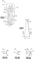
- a fan blade 20 is illustrated in Figure 1A having an airfoil 18 extending radially outwardly from a dovetail 24.
- a leading edge 21 and a trailing edge 22 define the forward and rear limits of the airfoil 18.
- a fan rotor 16 receives the dovetail 24 to mount the fan blade 20 with the airfoil 18 extending radially outwardly. As the rotor 16 is driven to rotate, it carries the fan blades 20 with it. There are higher stresses adjacent to the rotor 16, than occur radially outwardly of the rotor.
- Figure 2 shows a cross-section of the fan blade 20, at the airfoil 18.
- the leading edge 21 carries a cap 37 secured to a main body 28.
- a cover skin 32 closes off cavities or channels 30 in the main body 28.
- the main body 28, the cap 37 and the skin 32 may all be formed of various aluminum alloys. While aluminum alloys or aluminum may be utilized, other materials, such as titanium, titanium alloys, or other appropriate metals may be utilized.
- a plurality of ribs 26 separate channels 30 in the cross-section illustrated in Figure 2 . These channels 30 are closed off by the skin 32.
- the channels 30 extend from an open end inwardly to a closed side.
- the open end is closed off by skin 32. It is within the scope of this invention, however, that the channel extends across the width of the main body 28, and there are two skins on opposed sides of the main body 28.
- the channels may be filled with lighter weight filler material to provide stiffness, as known.
- a contact area 132 at the forward face of the ribs 26 serves as a mount point for the skin 32, and receives an adhesive.
- Chamfers 38 are formed at the break-edges, or the edges of the ribs 26, and will be described in more detail below.
- the channels 30 have a side extent formed by a compound radius 34 and 36, again to be described in greater detail below.
- Figure 3 shows the main body 28.
- the ribs 26 may be formed such that they tend to be thicker adjacent a radially inner edge 42, and become thinner when moving toward the radially outer portions 44.
- ribs 26 are thinner at radially outer end 44 than at the inner end 42.
- a thickness t 1 at the radially inner end 42 is greater than the thickness t 2 at the tip or radially outer end 44.
- a ratio of t 1 to t 2 may be between 1.1 and 8.
- the variation need not be linear as shown in Figure 4 , and may be different across the several ribs.
- a cross-section through the rib could be a trapezoid as shown in Figure 5A , wherein the bottom 50, which extends into the main body 28, is larger than the outer end 48 which attaches to the skin 32. Sides 46 are angled between the two ends 48 and 50.
- Figure 5B shows a rectangular cross-section for the rib 26 wherein the ends 52 and 54 are generally of the same thickness, and the sides 56 are generally perpendicular to those ends.
- Figure 5C shows yet another embodiment, wherein the ends 58 and 60 are of different thicknesses, and the sides 62 curve relative to each other along a particular radius.
- the upper end 48/52/58 actually has a more complex surface at its break-edges.
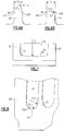
- Figure 6A shows the actual break-edge 38 on a rib 26.
- the contact area 132 which will actually contact the skin, and provide a surface for receiving adhesive and securing the skin should be maximized.
- the rib 26 has a nominal thickness t 3 at the upper end, if not for the chamfers 38. Stated another way, t 3 is the distance between sides 200 at the end of chamfers 38. The chamfers 38 extend for a thickness c measured in a plane perpendicular to the top edge 132.
- a ratio of c to t 3 according to the invention is between 0.02 and 0.15.
- the use of the chamfer at the break-edge location reduces the stress. There would otherwise be stress concentrations at that area.
- the amount of surface area available to provide a good adhesion to the cover is still adequate.
- Figure 6B shows an embodiment of a rib 64, wherein the break-edges are provided along a radius r 1 .
- the ratio of r 1 to t 3 is between 0.02 and 0.15.
- Figure 7 shows the surfaces 34 and 36 as illustrated in Figure 2 .
- the areas at that side of the channels 30 are prone to stress concentrations.
- a typical fillet, or single curve, may be considered for formation at that area to reduce stress.
- a compound fillet having two curves 34 and 36 is utilized. Curve 34 is formed along a radius r 2 while curve 36 is formed along a radius r 3 .
- a ratio of r 3 to r 2 is between 0.03 and 0.25. As is clear, r 2 is greater than r 3 . More narrowly, it may be between 0.06 and 0.13.
- the use of the compound fillet provides a great reduction in stress concentration, which would otherwise be maximized at the general location of the curve 36.
- Figure 8 shows a radially inner end, bottom or termination 100 of a channel 30.
- a compound curve or fillet including a bottom portion 104 formed at a radius r 4 and a side portion 102 formed at a radius r 5 , which merges into the side of the ribs.
- r 5 is greater than r 4 . Again, this arrangement reduces a stress concentration at the corners which would otherwise be induced into the cavity terminations.
- a ratio of r 4 to r 5 is between .03 and .25.
- the compound fillets as disclosed in Figures 7 and 8 reduce stress concentrations with minimum weight increase. Further, the compound fillets may be provided with minimal additional cost, because multi-pass machining is not required. Instead, a cutter with a compound radius shape may be utilized.
- the fan blade as described above reduces stresses that are raised during operations when mounted in a gas turbine engine.
Landscapes
- Engineering & Computer Science (AREA)
- Architecture (AREA)
- Mechanical Engineering (AREA)
- General Engineering & Computer Science (AREA)
- Structures Of Non-Positive Displacement Pumps (AREA)
Claims (3)
- Aube de soufflante (20) comprenant un corps principal (28) s'étendant entre un bord d'attaque (21) et un bord de fuite (22), et ayant des canaux (30) formés dans ledit corps principal (28) à partir d'au moins un côté ouvert avec une pluralité de nervures (26) s'étendant à travers le corps principal (28) entre les canaux (30), ladite aube de soufflante (20) ayant une queue d'aronde (24), et un profil aérodynamique (18) s'étendant radialement vers l'extérieur à partir de ladite queue d'aronde (24), lesdites nervures (26) ayant une épaisseur définie telle que mesurée à partir dudit bord d'attaque (21) vers ledit bord de fuite (22) ;
caractérisée en ce que :lesdites nervures (26) ont des bords de rupture (38 ; 66) au niveau des bords de ladite épaisseur, lesdites bords de rupture (38) étant formés pour s'étendre à l'opposé d'une face extérieure (132) au niveau dudit côté ouvert,dans laquelle lesdits bords de rupture (38) sont respectivement formés par un chanfrein, dans laquelle une épaisseur nominale (t3) de la nervure (26) peut être définie comme une épaisseur entre les côtés (200) de la nervure (26) au-delà du chanfrein (38), et l'épaisseur nominale (c) du chanfrein (38) peut être définie dans un plan perpendiculaire à ladite face extérieure (132) de ladite nervure (26), un rapport de ladite épaisseur nominale (c) du chanfrein (38) à l'épaisseur nominale (t3) de la nervure (26) étant compris entre 0,02 et 0,15 ; oulesdits bords de rupture (66) sont incurvés, dans laquelle un rapport d'un rayon (r1) dudit bord de rupture incurvé (66) à une épaisseur nominale (t3) de la nervure (26) mesurée entre les côtés (200) de la nervure (26) à des emplacements au-delà du bord de rupture incurvé (66) est compris entre 0,02 et 0,15. - Aube de soufflante (20) selon la revendication 1, dans laquelle un couvercle (32) ferme ledit au moins un côté ouvert, ledit couvercle (32) étant fixé auxdites nervures (26) sur ladite face extérieure (132).
- Aube de soufflante (20) selon la revendication 1 ou 2, dans laquelle ledit au moins un côté ouvert s'étend jusqu'à un côté fermé à l'intérieur dudit corps principal (28).
Applications Claiming Priority (1)
| Application Number | Priority Date | Filing Date | Title |
|---|---|---|---|
| US13/241,868 US8807925B2 (en) | 2011-09-23 | 2011-09-23 | Fan blade having internal rib break-edge |
Publications (3)
| Publication Number | Publication Date |
|---|---|
| EP2573321A2 EP2573321A2 (fr) | 2013-03-27 |
| EP2573321A3 EP2573321A3 (fr) | 2015-05-06 |
| EP2573321B1 true EP2573321B1 (fr) | 2020-06-24 |
Family
ID=46980790
Family Applications (1)
| Application Number | Title | Priority Date | Filing Date |
|---|---|---|---|
| EP12185421.0A Active EP2573321B1 (fr) | 2011-09-23 | 2012-09-21 | Aube de soufflante |
Country Status (2)
| Country | Link |
|---|---|
| US (1) | US8807925B2 (fr) |
| EP (1) | EP2573321B1 (fr) |
Families Citing this family (4)
| Publication number | Priority date | Publication date | Assignee | Title |
|---|---|---|---|---|
| US9121286B2 (en) * | 2012-04-24 | 2015-09-01 | United Technologies Corporation | Airfoil having tapered buttress |
| US9527262B2 (en) * | 2012-09-28 | 2016-12-27 | General Electric Company | Layered arrangement, hot-gas path component, and process of producing a layered arrangement |
| EP2896789B1 (fr) * | 2014-01-16 | 2018-03-07 | United Technologies Corporation | Pale de ventilateur à couvercle composite d'épaisseur variable |
| US20180038386A1 (en) * | 2016-08-08 | 2018-02-08 | United Technologies Corporation | Fan blade with composite cover |
Citations (1)
| Publication number | Priority date | Publication date | Assignee | Title |
|---|---|---|---|---|
| EP2239043A1 (fr) * | 2008-01-11 | 2010-10-13 | Sumitomo Electric Industries, Ltd. | Éléments de membrane de séparation, module de membrane de séparation et procédé de production d'éléments de membrane de séparation |
Family Cites Families (11)
| Publication number | Priority date | Publication date | Assignee | Title |
|---|---|---|---|---|
| US5536143A (en) | 1995-03-31 | 1996-07-16 | General Electric Co. | Closed circuit steam cooled bucket |
| US6048174A (en) * | 1997-09-10 | 2000-04-11 | United Technologies Corporation | Impact resistant hollow airfoils |
| US6039542A (en) * | 1997-12-24 | 2000-03-21 | General Electric Company | Panel damped hybrid blade |
| US6364616B1 (en) | 2000-05-05 | 2002-04-02 | General Electric Company | Submerged rib hybrid blade |
| US6994524B2 (en) * | 2004-01-26 | 2006-02-07 | United Technologies Corporation | Hollow fan blade for gas turbine engine |
| US7052238B2 (en) * | 2004-01-26 | 2006-05-30 | United Technologies Corporation | Hollow fan blade for gas turbine engine |
| US6994525B2 (en) * | 2004-01-26 | 2006-02-07 | United Technologies Corporation | Hollow fan blade for gas turbine engine |
| US7070391B2 (en) * | 2004-01-26 | 2006-07-04 | United Technologies Corporation | Hollow fan blade for gas turbine engine |
| US7458780B2 (en) * | 2005-08-15 | 2008-12-02 | United Technologies Corporation | Hollow fan blade for gas turbine engine |
| US8016561B2 (en) * | 2006-07-11 | 2011-09-13 | General Electric Company | Gas turbine engine fan assembly and method for assembling to same |
| GB2450934B (en) | 2007-07-13 | 2009-10-07 | Rolls Royce Plc | A Component with a damping filler |
-
2011
- 2011-09-23 US US13/241,868 patent/US8807925B2/en active Active
-
2012
- 2012-09-21 EP EP12185421.0A patent/EP2573321B1/fr active Active
Patent Citations (1)
| Publication number | Priority date | Publication date | Assignee | Title |
|---|---|---|---|---|
| EP2239043A1 (fr) * | 2008-01-11 | 2010-10-13 | Sumitomo Electric Industries, Ltd. | Éléments de membrane de séparation, module de membrane de séparation et procédé de production d'éléments de membrane de séparation |
Also Published As
| Publication number | Publication date |
|---|---|
| EP2573321A2 (fr) | 2013-03-27 |
| US20130078104A1 (en) | 2013-03-28 |
| EP2573321A3 (fr) | 2015-05-06 |
| US8807925B2 (en) | 2014-08-19 |
Similar Documents
| Publication | Publication Date | Title |
|---|---|---|
| EP2800876B1 (fr) | Pale de ventilateur en aluminium avec protection soudée | |
| EP2589781B1 (fr) | Réglage de pale de soufflante creuse utilisant des matériaux de remplissage distincts et procédé de conception d'une telle pale | |
| EP2752557B1 (fr) | Pâle de turbine sans plate-forme | |
| US6039542A (en) | Panel damped hybrid blade | |
| US10215027B2 (en) | Aluminum fan blade construction with welded cover | |
| EP2896790B1 (fr) | Pale de soufflante avec couvercle à bords effilés | |
| US10408227B2 (en) | Airfoil with stress-reducing fillet adapted for use in a gas turbine engine | |
| EP2500524A1 (fr) | Aube rotorique de moteur à turbine à gaz et ensemble associé | |
| CN106121734B (zh) | 一种叶片,包括该叶片的燃气涡轮机,以及制造该叶片的方法 | |
| EP3153664A1 (fr) | Construction de pale de ventilateur en aluminium comprenant un couvercle soude | |
| US8807925B2 (en) | Fan blade having internal rib break-edge | |
| EP2573324B1 (fr) | Aube de soufflante | |
| EP1609951A1 (fr) | Segment de virole intégral pour une aube de rotor | |
| EP2900934B1 (fr) | Moteur à turbine à gaz et procédé associé d'assemblage d'une aube directrice structurelle | |
| EP2573322B1 (fr) | Aube de soufflante | |
| EP2920072B1 (fr) | Aube rotorique de soufflante et procédé associé de fabrication | |
| EP2573323B1 (fr) | Aube de soufflante |
Legal Events
| Date | Code | Title | Description |
|---|---|---|---|
| PUAI | Public reference made under article 153(3) epc to a published international application that has entered the european phase |
Free format text: ORIGINAL CODE: 0009012 |
|
| AK | Designated contracting states |
Kind code of ref document: A2 Designated state(s): AL AT BE BG CH CY CZ DE DK EE ES FI FR GB GR HR HU IE IS IT LI LT LU LV MC MK MT NL NO PL PT RO RS SE SI SK SM TR |
|
| AX | Request for extension of the european patent |
Extension state: BA ME |
|
| PUAL | Search report despatched |
Free format text: ORIGINAL CODE: 0009013 |
|
| AK | Designated contracting states |
Kind code of ref document: A3 Designated state(s): AL AT BE BG CH CY CZ DE DK EE ES FI FR GB GR HR HU IE IS IT LI LT LU LV MC MK MT NL NO PL PT RO RS SE SI SK SM TR |
|
| AX | Request for extension of the european patent |
Extension state: BA ME |
|
| RIC1 | Information provided on ipc code assigned before grant |
Ipc: F01D 5/14 20060101AFI20150331BHEP |
|
| 17P | Request for examination filed |
Effective date: 20151106 |
|
| RBV | Designated contracting states (corrected) |
Designated state(s): AL AT BE BG CH CY CZ DE DK EE ES FI FR GB GR HR HU IE IS IT LI LT LU LV MC MK MT NL NO PL PT RO RS SE SI SK SM TR |
|
| RAP1 | Party data changed (applicant data changed or rights of an application transferred) |
Owner name: UNITED TECHNOLOGIES CORPORATION |
|
| GRAP | Despatch of communication of intention to grant a patent |
Free format text: ORIGINAL CODE: EPIDOSNIGR1 |
|
| STAA | Information on the status of an ep patent application or granted ep patent |
Free format text: STATUS: GRANT OF PATENT IS INTENDED |
|
| INTG | Intention to grant announced |
Effective date: 20190801 |
|
| GRAJ | Information related to disapproval of communication of intention to grant by the applicant or resumption of examination proceedings by the epo deleted |
Free format text: ORIGINAL CODE: EPIDOSDIGR1 |
|
| STAA | Information on the status of an ep patent application or granted ep patent |
Free format text: STATUS: REQUEST FOR EXAMINATION WAS MADE |
|
| GRAP | Despatch of communication of intention to grant a patent |
Free format text: ORIGINAL CODE: EPIDOSNIGR1 |
|
| STAA | Information on the status of an ep patent application or granted ep patent |
Free format text: STATUS: GRANT OF PATENT IS INTENDED |
|
| INTC | Intention to grant announced (deleted) | ||
| INTG | Intention to grant announced |
Effective date: 20200107 |
|
| GRAS | Grant fee paid |
Free format text: ORIGINAL CODE: EPIDOSNIGR3 |
|
| GRAA | (expected) grant |
Free format text: ORIGINAL CODE: 0009210 |
|
| STAA | Information on the status of an ep patent application or granted ep patent |
Free format text: STATUS: THE PATENT HAS BEEN GRANTED |
|
| AK | Designated contracting states |
Kind code of ref document: B1 Designated state(s): AL AT BE BG CH CY CZ DE DK EE ES FI FR GB GR HR HU IE IS IT LI LT LU LV MC MK MT NL NO PL PT RO RS SE SI SK SM TR |
|
| REG | Reference to a national code |
Ref country code: GB Ref legal event code: FG4D |
|
| REG | Reference to a national code |
Ref country code: CH Ref legal event code: EP |
|
| REG | Reference to a national code |
Ref country code: DE Ref legal event code: R096 Ref document number: 602012070856 Country of ref document: DE |
|
| REG | Reference to a national code |
Ref country code: AT Ref legal event code: REF Ref document number: 1284088 Country of ref document: AT Kind code of ref document: T Effective date: 20200715 |
|
| REG | Reference to a national code |
Ref country code: IE Ref legal event code: FG4D |
|
| PG25 | Lapsed in a contracting state [announced via postgrant information from national office to epo] |
Ref country code: FI Free format text: LAPSE BECAUSE OF FAILURE TO SUBMIT A TRANSLATION OF THE DESCRIPTION OR TO PAY THE FEE WITHIN THE PRESCRIBED TIME-LIMIT Effective date: 20200624 Ref country code: NO Free format text: LAPSE BECAUSE OF FAILURE TO SUBMIT A TRANSLATION OF THE DESCRIPTION OR TO PAY THE FEE WITHIN THE PRESCRIBED TIME-LIMIT Effective date: 20200924 Ref country code: SE Free format text: LAPSE BECAUSE OF FAILURE TO SUBMIT A TRANSLATION OF THE DESCRIPTION OR TO PAY THE FEE WITHIN THE PRESCRIBED TIME-LIMIT Effective date: 20200624 Ref country code: LT Free format text: LAPSE BECAUSE OF FAILURE TO SUBMIT A TRANSLATION OF THE DESCRIPTION OR TO PAY THE FEE WITHIN THE PRESCRIBED TIME-LIMIT Effective date: 20200624 Ref country code: GR Free format text: LAPSE BECAUSE OF FAILURE TO SUBMIT A TRANSLATION OF THE DESCRIPTION OR TO PAY THE FEE WITHIN THE PRESCRIBED TIME-LIMIT Effective date: 20200925 |
|
| REG | Reference to a national code |
Ref country code: LT Ref legal event code: MG4D |
|
| PG25 | Lapsed in a contracting state [announced via postgrant information from national office to epo] |
Ref country code: RS Free format text: LAPSE BECAUSE OF FAILURE TO SUBMIT A TRANSLATION OF THE DESCRIPTION OR TO PAY THE FEE WITHIN THE PRESCRIBED TIME-LIMIT Effective date: 20200624 Ref country code: HR Free format text: LAPSE BECAUSE OF FAILURE TO SUBMIT A TRANSLATION OF THE DESCRIPTION OR TO PAY THE FEE WITHIN THE PRESCRIBED TIME-LIMIT Effective date: 20200624 Ref country code: LV Free format text: LAPSE BECAUSE OF FAILURE TO SUBMIT A TRANSLATION OF THE DESCRIPTION OR TO PAY THE FEE WITHIN THE PRESCRIBED TIME-LIMIT Effective date: 20200624 Ref country code: BG Free format text: LAPSE BECAUSE OF FAILURE TO SUBMIT A TRANSLATION OF THE DESCRIPTION OR TO PAY THE FEE WITHIN THE PRESCRIBED TIME-LIMIT Effective date: 20200924 |
|
| REG | Reference to a national code |
Ref country code: NL Ref legal event code: MP Effective date: 20200624 |
|
| REG | Reference to a national code |
Ref country code: AT Ref legal event code: MK05 Ref document number: 1284088 Country of ref document: AT Kind code of ref document: T Effective date: 20200624 |
|
| PG25 | Lapsed in a contracting state [announced via postgrant information from national office to epo] |
Ref country code: NL Free format text: LAPSE BECAUSE OF FAILURE TO SUBMIT A TRANSLATION OF THE DESCRIPTION OR TO PAY THE FEE WITHIN THE PRESCRIBED TIME-LIMIT Effective date: 20200624 Ref country code: AL Free format text: LAPSE BECAUSE OF FAILURE TO SUBMIT A TRANSLATION OF THE DESCRIPTION OR TO PAY THE FEE WITHIN THE PRESCRIBED TIME-LIMIT Effective date: 20200624 |
|
| PG25 | Lapsed in a contracting state [announced via postgrant information from national office to epo] |
Ref country code: SM Free format text: LAPSE BECAUSE OF FAILURE TO SUBMIT A TRANSLATION OF THE DESCRIPTION OR TO PAY THE FEE WITHIN THE PRESCRIBED TIME-LIMIT Effective date: 20200624 Ref country code: RO Free format text: LAPSE BECAUSE OF FAILURE TO SUBMIT A TRANSLATION OF THE DESCRIPTION OR TO PAY THE FEE WITHIN THE PRESCRIBED TIME-LIMIT Effective date: 20200624 Ref country code: IT Free format text: LAPSE BECAUSE OF FAILURE TO SUBMIT A TRANSLATION OF THE DESCRIPTION OR TO PAY THE FEE WITHIN THE PRESCRIBED TIME-LIMIT Effective date: 20200624 Ref country code: CZ Free format text: LAPSE BECAUSE OF FAILURE TO SUBMIT A TRANSLATION OF THE DESCRIPTION OR TO PAY THE FEE WITHIN THE PRESCRIBED TIME-LIMIT Effective date: 20200624 Ref country code: ES Free format text: LAPSE BECAUSE OF FAILURE TO SUBMIT A TRANSLATION OF THE DESCRIPTION OR TO PAY THE FEE WITHIN THE PRESCRIBED TIME-LIMIT Effective date: 20200624 Ref country code: PT Free format text: LAPSE BECAUSE OF FAILURE TO SUBMIT A TRANSLATION OF THE DESCRIPTION OR TO PAY THE FEE WITHIN THE PRESCRIBED TIME-LIMIT Effective date: 20201026 Ref country code: EE Free format text: LAPSE BECAUSE OF FAILURE TO SUBMIT A TRANSLATION OF THE DESCRIPTION OR TO PAY THE FEE WITHIN THE PRESCRIBED TIME-LIMIT Effective date: 20200624 Ref country code: AT Free format text: LAPSE BECAUSE OF FAILURE TO SUBMIT A TRANSLATION OF THE DESCRIPTION OR TO PAY THE FEE WITHIN THE PRESCRIBED TIME-LIMIT Effective date: 20200624 |
|
| PG25 | Lapsed in a contracting state [announced via postgrant information from national office to epo] |
Ref country code: IS Free format text: LAPSE BECAUSE OF FAILURE TO SUBMIT A TRANSLATION OF THE DESCRIPTION OR TO PAY THE FEE WITHIN THE PRESCRIBED TIME-LIMIT Effective date: 20201024 Ref country code: PL Free format text: LAPSE BECAUSE OF FAILURE TO SUBMIT A TRANSLATION OF THE DESCRIPTION OR TO PAY THE FEE WITHIN THE PRESCRIBED TIME-LIMIT Effective date: 20200624 Ref country code: SK Free format text: LAPSE BECAUSE OF FAILURE TO SUBMIT A TRANSLATION OF THE DESCRIPTION OR TO PAY THE FEE WITHIN THE PRESCRIBED TIME-LIMIT Effective date: 20200624 |
|
| RAP2 | Party data changed (patent owner data changed or rights of a patent transferred) |
Owner name: RAYTHEON TECHNOLOGIES CORPORATION |
|
| REG | Reference to a national code |
Ref country code: DE Ref legal event code: R097 Ref document number: 602012070856 Country of ref document: DE |
|
| PG25 | Lapsed in a contracting state [announced via postgrant information from national office to epo] |
Ref country code: DK Free format text: LAPSE BECAUSE OF FAILURE TO SUBMIT A TRANSLATION OF THE DESCRIPTION OR TO PAY THE FEE WITHIN THE PRESCRIBED TIME-LIMIT Effective date: 20200624 Ref country code: MC Free format text: LAPSE BECAUSE OF FAILURE TO SUBMIT A TRANSLATION OF THE DESCRIPTION OR TO PAY THE FEE WITHIN THE PRESCRIBED TIME-LIMIT Effective date: 20200624 |
|
| PLBE | No opposition filed within time limit |
Free format text: ORIGINAL CODE: 0009261 |
|
| REG | Reference to a national code |
Ref country code: CH Ref legal event code: PL |
|
| STAA | Information on the status of an ep patent application or granted ep patent |
Free format text: STATUS: NO OPPOSITION FILED WITHIN TIME LIMIT |
|
| 26N | No opposition filed |
Effective date: 20210325 |
|
| REG | Reference to a national code |
Ref country code: BE Ref legal event code: MM Effective date: 20200930 |
|
| PG25 | Lapsed in a contracting state [announced via postgrant information from national office to epo] |
Ref country code: LU Free format text: LAPSE BECAUSE OF NON-PAYMENT OF DUE FEES Effective date: 20200921 |
|
| PG25 | Lapsed in a contracting state [announced via postgrant information from national office to epo] |
Ref country code: SI Free format text: LAPSE BECAUSE OF FAILURE TO SUBMIT A TRANSLATION OF THE DESCRIPTION OR TO PAY THE FEE WITHIN THE PRESCRIBED TIME-LIMIT Effective date: 20200624 Ref country code: LI Free format text: LAPSE BECAUSE OF NON-PAYMENT OF DUE FEES Effective date: 20200930 Ref country code: IE Free format text: LAPSE BECAUSE OF NON-PAYMENT OF DUE FEES Effective date: 20200921 Ref country code: CH Free format text: LAPSE BECAUSE OF NON-PAYMENT OF DUE FEES Effective date: 20200930 Ref country code: BE Free format text: LAPSE BECAUSE OF NON-PAYMENT OF DUE FEES Effective date: 20200930 |
|
| PG25 | Lapsed in a contracting state [announced via postgrant information from national office to epo] |
Ref country code: TR Free format text: LAPSE BECAUSE OF FAILURE TO SUBMIT A TRANSLATION OF THE DESCRIPTION OR TO PAY THE FEE WITHIN THE PRESCRIBED TIME-LIMIT Effective date: 20200624 Ref country code: MT Free format text: LAPSE BECAUSE OF FAILURE TO SUBMIT A TRANSLATION OF THE DESCRIPTION OR TO PAY THE FEE WITHIN THE PRESCRIBED TIME-LIMIT Effective date: 20200624 Ref country code: CY Free format text: LAPSE BECAUSE OF FAILURE TO SUBMIT A TRANSLATION OF THE DESCRIPTION OR TO PAY THE FEE WITHIN THE PRESCRIBED TIME-LIMIT Effective date: 20200624 |
|
| PG25 | Lapsed in a contracting state [announced via postgrant information from national office to epo] |
Ref country code: MK Free format text: LAPSE BECAUSE OF FAILURE TO SUBMIT A TRANSLATION OF THE DESCRIPTION OR TO PAY THE FEE WITHIN THE PRESCRIBED TIME-LIMIT Effective date: 20200624 |
|
| P01 | Opt-out of the competence of the unified patent court (upc) registered |
Effective date: 20230520 |
|
| REG | Reference to a national code |
Ref country code: DE Ref legal event code: R081 Ref document number: 602012070856 Country of ref document: DE Owner name: RTX CORPORATION (N.D.GES.D. STAATES DELAWARE),, US Free format text: FORMER OWNER: UNITED TECHNOLOGIES CORPORATION, FARMINGTON, CONN., US |
|
| PGFP | Annual fee paid to national office [announced via postgrant information from national office to epo] |
Ref country code: DE Payment date: 20250820 Year of fee payment: 14 |
|
| PGFP | Annual fee paid to national office [announced via postgrant information from national office to epo] |
Ref country code: GB Payment date: 20250820 Year of fee payment: 14 |
|
| PGFP | Annual fee paid to national office [announced via postgrant information from national office to epo] |
Ref country code: FR Payment date: 20250821 Year of fee payment: 14 |