EP2573331A2 - Eintrittsmassenstrom- und Eintrittswinkelsteuerung - Google Patents
Eintrittsmassenstrom- und Eintrittswinkelsteuerung Download PDFInfo
- Publication number
- EP2573331A2 EP2573331A2 EP12184361A EP12184361A EP2573331A2 EP 2573331 A2 EP2573331 A2 EP 2573331A2 EP 12184361 A EP12184361 A EP 12184361A EP 12184361 A EP12184361 A EP 12184361A EP 2573331 A2 EP2573331 A2 EP 2573331A2
- Authority
- EP
- European Patent Office
- Prior art keywords
- flow rate
- fluid flow
- impingement angle
- control device
- fluid
- Prior art date
- Legal status (The legal status is an assumption and is not a legal conclusion. Google has not performed a legal analysis and makes no representation as to the accuracy of the status listed.)
- Withdrawn
Links
Images


Classifications
-
- F—MECHANICAL ENGINEERING; LIGHTING; HEATING; WEAPONS; BLASTING
- F01—MACHINES OR ENGINES IN GENERAL; ENGINE PLANTS IN GENERAL; STEAM ENGINES
- F01D—NON-POSITIVE DISPLACEMENT MACHINES OR ENGINES, e.g. STEAM TURBINES
- F01D17/00—Regulating or controlling by varying flow
- F01D17/10—Final actuators
- F01D17/12—Final actuators arranged in stator parts
- F01D17/14—Final actuators arranged in stator parts varying effective cross-sectional area of nozzles or guide conduits
- F01D17/141—Final actuators arranged in stator parts varying effective cross-sectional area of nozzles or guide conduits by means of shiftable members or valves obturating part of the flow path
-
- F—MECHANICAL ENGINEERING; LIGHTING; HEATING; WEAPONS; BLASTING
- F02—COMBUSTION ENGINES; HOT-GAS OR COMBUSTION-PRODUCT ENGINE PLANTS
- F02C—GAS-TURBINE PLANTS; AIR INTAKES FOR JET-PROPULSION PLANTS; CONTROLLING FUEL SUPPLY IN AIR-BREATHING JET-PROPULSION PLANTS
- F02C7/00—Features, components parts, details or accessories, not provided for in, or of interest apart form groups F02C1/00 - F02C6/00; Air intakes for jet-propulsion plants
- F02C7/04—Air intakes for gas-turbine plants or jet-propulsion plants
- F02C7/042—Air intakes for gas-turbine plants or jet-propulsion plants having variable geometry
-
- F—MECHANICAL ENGINEERING; LIGHTING; HEATING; WEAPONS; BLASTING
- F02—COMBUSTION ENGINES; HOT-GAS OR COMBUSTION-PRODUCT ENGINE PLANTS
- F02C—GAS-TURBINE PLANTS; AIR INTAKES FOR JET-PROPULSION PLANTS; CONTROLLING FUEL SUPPLY IN AIR-BREATHING JET-PROPULSION PLANTS
- F02C7/00—Features, components parts, details or accessories, not provided for in, or of interest apart form groups F02C1/00 - F02C6/00; Air intakes for jet-propulsion plants
- F02C7/04—Air intakes for gas-turbine plants or jet-propulsion plants
- F02C7/05—Air intakes for gas-turbine plants or jet-propulsion plants having provisions for obviating the penetration of damaging objects or particles
- F02C7/055—Air intakes for gas-turbine plants or jet-propulsion plants having provisions for obviating the penetration of damaging objects or particles with intake grids, screens or guards
-
- F—MECHANICAL ENGINEERING; LIGHTING; HEATING; WEAPONS; BLASTING
- F02—COMBUSTION ENGINES; HOT-GAS OR COMBUSTION-PRODUCT ENGINE PLANTS
- F02C—GAS-TURBINE PLANTS; AIR INTAKES FOR JET-PROPULSION PLANTS; CONTROLLING FUEL SUPPLY IN AIR-BREATHING JET-PROPULSION PLANTS
- F02C9/00—Controlling gas-turbine plants; Controlling fuel supply in air- breathing jet-propulsion plants
- F02C9/16—Control of working fluid flow
- F02C9/20—Control of working fluid flow by throttling; by adjusting vanes
Definitions
- One or more aspects of the present invention relate to control of inlet fluid flow and impingement angle of fluid flow in gas turbines.
- IGVs In many conventional gas turbines, inlet guide vanes (IGV) are the primary mechanisms for flow control. IGVs serve two primary purposes - controlling the flow rate of air entering the compressor, and setting the impingement angle of the air entering the compressor. In many cases, both of these purposes cannot be optimally fulfilled using IGVs alone.
- variable guide vanes which comprises multiple stages of vanes
- VGVs are more or less limited to new units. Retrofitting existing IGV based turbine systems with VGVs is impractical, uneconomical and technically difficult.
- a non-limiting aspect of the present invention relates to a compressor of a gas turbine system arranged to compress fluid for combustion in a combustor with fuel.
- the compressor comprises a fluid flow control device and an impingement angle control device downstream of the fluid flow control device.
- the fluid flow control device is arranged to control a fluid flow rate of fluid entering an inlet of the compressor, and the impingement angle control device is arranged to control an impingement angle of the fluid flowing to rotor blades in the compressor.
- the fluid flow control device and the impingement angle control device are arranged to be independently operable.
- Another non-limiting aspect of the present invention relates to a gas turbine system.
- the turbine system comprises a compressor, a fuel delivery unit, a combustor, a turbine, and a system controller.
- the compressor is arranged to compress fluid
- the fuel delivery unit is arranged to deliver fuel
- the combustor is arranged to mix the compressed fluid discharged from the compressor with the fuel from the fuel delivery unit and combust the fuel and fluid mixture
- the turbine is arranged convert heat energy released from the combustion of the fuel and fluid mixture to mechanical energy for driving a load.
- the system controller is arranged to control an overall operation of the gas turbine system.
- the compressor comprises a fluid flow control device and an impingement angle control device downstream of the fluid flow control device.
- the fluid flow control device is arranged to control a fluid flow rate of fluid entering an inlet of the compressor based on a fluid flow rate control signal from the system controller, and the impingement angle control device is arranged to control an impingement angle of the fluid flowing to rotor blades in the compressor based on an impingement angle control signal from the system controller.
- the fluid flow control device and the impingement angle control device are arranged to be independently operable.
- Another non-limiting aspect of the present invention relates to a method to control a fluid flow rate of fluid entering an inlet of a compressor of a gas turbine system and/or to control an impingement angle of the fluid flowing to rotor blades in the compressor.
- the method may be performed at or on behalf of a system controller of the gas turbine system.
- the method comprises receiving one or more sensor signals from one or more of the compressor, a fuel delivery unit, a combustor and a turbine of the gas turbine system or receiving one or more externally provided operation input signals or receiving both.
- the method also comprises setting a desired fluid flow rate or setting a desired impingement angle or setting both based on the sensor and/or operation input signals.
- the method further comprises transmitting a fluid flow rate control signal in accordance with the desired fluid flow rate to a fluid flow control device or transmitting an impingement angle control signal in accordance with the desired impingement angle to an impingement angle control device or transmitting both.
- Novel apparatus, system and method for controlling a fluid flow rate and impingement angle of a flow of fluid entering a compressor of a gas turbine system are described.
- the fluid flow rate and the impingement angle will be referred to as fluid flow parameters. Due at least in part to the ability to independently control each of the fluid flow parameters provided operational flexibility is enhanced by the novel inventive aspects.
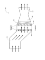
- Figure 1 illustrates an example gas turbine system 100 according to an aspect of the present invention.
- the system 100 includes a combustor 130 that generates high energy gases to drive a gas turbine 140 which can be used to drive a load 160 to perform useful work such as generating electricity.
- the turbine 140 also drives a shaft 150 which is operatively coupled to a compressor 110, which compresses and provides compressed fluid containing oxidant, e.g., air, to the combustor 130.
- the system 100 includes a fuel delivery unit 120 which delivers fuel to the combustor 130.
- a system controller 170 is arranged to control the operation of the system 100.
- the system controller 170 receives as inputs sensor signals from sensors monitoring the system units (compressor 110, fuel delivery unit 120, combustor 130, and turbine 140). While not shown, sensors can also be provided to monitor the load 160 and the shaft 150. The system controller 170 can also receive operation inputs such as an instruction from an operator to start up, partial load operation, full load operation, shut down, and so on. Based on the inputs, the system controller 170 outputs control signals to the system units to control the system operation. To minimize clutter in Figure 1 , sensor signals from the units 110, 120, 130 and 140 to the system controller 170 and control signals from the controller 170 to the units 110, 120, 130 and 140 are represented as dashed arrows.
- FIG. 2 illustrates an example intake 200 of the gas turbine system 100 according to an aspect of the present invention.
- flow of gaseous fluid that includes oxidant(s), e.g., air is represented as thick arrows.
- the intake 200 comprises a fluid flow control device 220 and an impingement angle control device 230.
- the fluid flow control device 220 is arranged to control a fluid flow rate of the fluid entering an inlet 210 of the compressor 110. Downstream of the fluid flow control device 220, the impingement angle control device 230 is arranged to control an impingement angle of the fluid flowing to rotor blades 240 in the compressor 110.
- the fluid flow control device 220 and the impingement angle control device 230 are independently operable, i.e., each can be controlled independent of the other. Recall that in conventional turbines, IGVs are used to set both the flow rate and the impingement angle. Unfortunately, an optimum combination of flow rate and impingement angle is difficult to achieve using the IGVs alone.
- the intake 200 being able to independently control the flow rate and the impingement angle, allows the optimum or close to optimum combination to be achieved.
- one or both of the fluid flow control device 220 and the impingement angle control device 230 are controlled through control signals, shown as dashed arrows in Figure 2 , received from the system controller 170.
- the fluid flow control device 220 is arranged to control the fluid flow rate based on a fluid flow rate control signal received from the system controller 170
- the impingement angle control device 230 is arranged to control the impingement angle based on an impingement angle control signal also received from the system controller 170.
- the compressor 110 can include multiple stages of rotor blades 240 downstream of the impingement angle control device 230.
- the impingement angle of the fluid flow is particularly relevant to the first stage of the rotor blades 240.
- the impingement angle on the first stage can influence the impingement angles on subsequent stages.
- the impingement angle on the first stage is controlled in consideration of the subsequent stages, for example, to reduce or eliminate risk of stall.
- An example of the fluid flow control device 220 is a plurality of louvers. Note that any controllable mechanism - which can be a single device or a combination of devices - capable of varying the fluid flow rate can serve as the fluid flow control device 220.
- An example of the impingement angle control device 230 is a plurality of controllable dynamic foils.
- IGVs are examples of such dynamic foils.
- VGVs may also serve as controllable dynamic foils.
- Such a system may provide very fine way to control of both the fluid flow rate and the impingement angles.
- any controllable mechanism - which can be a single device or a combination of devices - capable of varying the impingement angle can serve as the impingement angle control device 230.
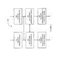
- Figure 3 is an example flowchart of a method 300 performed at or on behalf of the system controller 170 to control one or both of the fluid flow rate of the fluid entering the inlet 210 of the compressor 110, and the impingement angle of the fluid flowing to the rotor blades 240 of the compressor.
- the system controller 170 controls the operations of one or both of the fluid flow control device 220 and the impingement angle control device 230.
- the system controller 170 receives sensor signal(s) from any one or more units of the gas turbine system 100.
- the sensor signals may be from sensors monitoring the compressor 110, the fuel delivery unit 120, the combustor 130, and/or the turbine 140.
- Examples of sensor signals include signals indicating fluid velocity, density, discharge temperature and oxidant levels from the compressor 110; Wobbe Index and fuel temperature from the fuel delivery unit 120; flame temperature and combustion pressure from the combustor 130; and rotor speed and acceleration from the turbine 140.
- the system controller 170 receives externally provided operation input signal or signals.
- externally provided signals are any signals that are not provided through the sensors, but which nonetheless can factor into the decision making process in operating the gas turbine system 100.
- the system controller 170 may receive the operation input signals through an interface with another system or may receive the operation signals directly from an operator. Examples of operation input signals include instructions to start up, partial load operation, full load operation, shut down, and so on.
- the system controller 170 may maintain the full load operation based on the sensor inputs, at least until the system controller 170 receives operation input signals instructing that the operation mode of the system 100 be changed, e.g., to shut down.
- step 310 when the sensor signals are present, step 310 may be performed, and when the operation inputs are present, step 320 may be performed.
- the order in which steps 310 and 320 are performed is not particularly limited. Also, it is contemplated that the method 300 can proceed even when only one of the steps 310 and 320 is performed. In other words, completing both steps is not a prerequisite to move on to the subsequent steps of the method 300.
- step 330 the system controller 170 sets a desired fluid flow rate based the sensor input signals when present, based on the operation input signals when present, or based on sensor and operation input signals when both signal types are present. Note that even when both signal types are present, the system controller 170 in step 330 may still set the desired fluid flow rate based on one or the other signal types.
- step 340 the system controller 170 sets a desired impingement angle based the sensor input signals when present, based on the operation input signals when present, or based on sensor and operation input signals when both signal types are present. Again, the desired impingement angle may still set the desired impingement angle based on one signal type even when both signal types are available.
- steps 330 and 340 are performed is not particularly limited. Either or both of these steps can be performed, depending on the circumstances, when one or both of the sensor and operation input signals are present. Steps 330 and 340 may be performed independent of each other. As a result, the system controller 170 may perform these steps in parallel, may perform one step but not the other depending on the circumstances, or may perform both steps one after the other.
- the system controller 170 sets an optimum combination of the desired flow rate and impingement angle.
- the desired fluid flow rate should be set taking into consideration the actual impingement angle.
- the actual impingement angle may be directly determined, for example, through a signal from a sensor. But in another aspect, the actual impingement angle can be calculated or inferred through other measurable parameters. For example, the actual impingement angle can be determined in consideration of the fluid density and velocity, the shape of the foils, rotational speed of the rotor blades, and so on.
- the desired impingement angle that was set in a previous performance of step 340 can be assumed to be the actual impingement angle.
- the system controller 170 may set the desired flow rate based on the actual impingement angle in step 330.
- the desired impingement angle should be set taking into consideration the actual fluid flow rate.
- the actual fluid flow rate may be directly determined or indirectly determined, i.e., calculated or inferred, based on other measurable parameters; and/or assumed to be the same as the desired fluid flow rate set in a previous performance of step 330.
- some or all measurable parameters used to indirectly determine the actual fluid flow rate may be the same or different from the parameters used to determine the actual impingement angle.
- the system controller 170 Upon setting the desired fluid flow rate in step 330, the system controller 170 transmits a fluid flow rate control signal in accordance with the desired fluid flow rate to the fluid flow control device 220 in step 350. Likewise, upon determining the desired impingement angle in step 340, the system controller 170 transmits an impingement angle control signal in accordance with the desired impingement angle to the impingement angle control device 230. As noted above and illustrated in Figures 1 and 2 , the fluid flow control device 220 controls the fluid flow rate based on the fluid flow rate control signal and the impingement angle control device 230 controls the impingement angle based on the impingement angle control signal.
- the fluid flow parameters - fluid flow rate and impingement angle - are defined at a common location, e.g., at a point immediately downstream of the impingement angle control device 230. At this point, the fluid has passed through the impingement angle control device 230.
- the impingement angle control device 230 will in most instances physically alter the direction of the fluid flow. As such, the impingement angle control device 230 can also influence the flow rate.
- a conventional compressor with IGVs can be retrofitted to incorporate the fluid flow control device 220 and the existing IGVs can be used as the impingement angle control device 230.
- the impingement angle control device 230 is downstream of the fluid flow control device 220. Thus, after the fluid flow control device 220 controls the rate flowing therethrough, the flow rate can be further impacted after flowing through the impingement angle control device 230
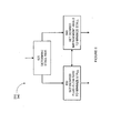
- Figure 4 illustrates a flow chart of an example process to implement steps 330 and 350 to account for the impact that the impingement angle control device 230 may have on the fluid flow rate according to an aspect of the present invention.
- the system controller 170 determines a flow rate change based on the impingement angle.
- the flow rate change is defmed as an amount of change in the flow rate of the fluid passing through the impingement angle control device 230. For example, one may expect that the amount of flow rate change would correspond to the severity of the change in the direction of the fluid flow represented by the impingement angle.
- step 420 the system controller 170 sets a compensation fluid flow rate that is sufficient to compensate for flow rate change that occurs through the impingement angle control device 230 such that the desired fluid flow rate will result after having passed through the impingement angle control device 230.
- the compensation fluid flow rate is the flow rate of the fluid before passing through the impingement angle control device 230. For example, if the desired fluid flow rate is X and the flow rate change is - ⁇ X (negative since the flow rate is likely to be reduced), then the compensation flow rate could be X + ⁇ X .
- the system controller 170 can and should take other factors into account such as the geometry of the intake 200, density and velocity of the fluid at intake, etc. (which can be provided through sensors) so that more accurate results can be calculated.
- the system controller transmits the fluid flow rate control signal in accordance with the compensation fluid flow rate.
- IGVs of retrofitted conventional systems may have significant impact on the fluid flow rate, thus making the above-described compensation process desirable.
- dynamic foils can be designed focusing more on impingement and less on flow control.
- the new IGVs could be designed to limit its influence on the flow.
- the compressor 110 can include subsequent stages of rotor blades 240 downstream. That is, there can be a plurality of rotor blade stages in which the first stage is shown in Figure 2 .
- the fluid flow rate and/or the impingement angle of the fluid to the first stage can effect or influence the fluid flow rates and/or the impingement angles on subsequent stages, which in turn can impact the overall performance of the gas turbine system 110.
- NOx and CO emissions may increase or decrease, system efficiency may rise or fall, change in the risk of stall, and so on.
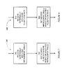
- Figure 5 illustrates a flow chart of an example process to implement steps 330 and 340 to account for effects on subsequent stages when determining one or both of the fluid flow parameters according to an aspect of the present invention.
- the system controller 170 determines the effects of the fluid flow rate and the impingement angle on fluid flow rates impingement angles to one or more subsequent stages of rotor blades.
- the system controller 170 sets the desired fluid flow rate based on a consideration of the effects to the subsequent rotor blade stages.
- the system controller 170 sets the desired impingement angle also based on the same or similar considerations.
- steps 530 and 540 are performed is not particularly limited. Either or both of these steps can be performed. Also, these steps may be performed independent of each other, e.g., performed in parallel, perform one but not the other, perform both steps one after the other, and so on.
- Figure 6 illustrates a flow chart of an example process to implement steps 330 and 340 to account reduce or even eliminate stall possibilities in determining one or both of the fluid flow parameters according to an aspect of the present invention.
- the system controller 170 determines a risk of stall based on the sensor signals. For example, based on sensor signals from the fuel delivery unit 120 and the compressor 110, the system controller may determine that the fuel-to-air mixture being delivered to the combustor 130 is approaching lean blowout limit. As another example, acoustical sensors from the combustor 130 may indicate flame instability.
- step 630 the system controller 170 sets the desired fluid flow rate so as to minimize the stall risk.
- the fluid flow rate may be reduced such that the richness of the fuel mixture is increased.
- step 640 the system controller 170 sets the desired impingement angle also so as to minimize the stall risk.
- the order in which steps 630 and 640 are performed is not particularly limited. Either or both of these steps can be performed. Also, these steps may be performed independent of each other, e.g., performed in parallel, perform one but not the other, perform both steps one after the other, and so on.
- both fluid flow parameters are set by the system controller 170 based on sensor and/or operation input signals. But there may be some circumstances in which one but not both fluid flow parameters is specified externally, i.e., one fluid flow parameter is specified outside of the system controller 170.
- the external specification can be received as an operation input in step 320. If the fluid flow rate is externally specified, then steps 330 and 350 decompose into transmitting the fluid flow rate control signal corresponding to the specified fluid flow rate. If the impingement angle is externally specified in step 320, then steps 340 and 360 decompose into transmitting the impingement angle control signal corresponding to the specified impingement angle.
- Figure 7 and 8 illustrate flow charts of example processes to implement steps 330 and 340, respectively, to determine one fluid flow parameter when the other is externally specified according to aspects of the present invention.
- the system controller 170 receives the externally specified impingement angle in step 710.
- the system controller 170 sets the desired fluid flow rate based on the externally specified impingement angle.
- the system controller 170 may also determine the desired fluid flow rate based on the sensor and/or other operation input signals in addition to the externally specified impingement angle.
- the system controller 170 receives the externally fluid flow rate in step 810. Then in step 820, the system controller 170 sets the desired impingement angle based on the externally specified fluid flow rate. Again, while not specifically indicated in Figure 8 , the system controller 170 may also determine the desired impingement angle based on the sensor and/or other operation input signals in addition to the externally specified fluid flow rate.
Landscapes
- Engineering & Computer Science (AREA)
- Chemical & Material Sciences (AREA)
- Combustion & Propulsion (AREA)
- Mechanical Engineering (AREA)
- General Engineering & Computer Science (AREA)
- Physics & Mathematics (AREA)
- Geometry (AREA)
- Fluid Mechanics (AREA)
- Control Of Positive-Displacement Air Blowers (AREA)
Applications Claiming Priority (1)
| Application Number | Priority Date | Filing Date | Title |
|---|---|---|---|
| US13/243,894 US20130074512A1 (en) | 2011-09-23 | 2011-09-23 | Inlet fluid flow and impingement angle control |
Publications (1)
| Publication Number | Publication Date |
|---|---|
| EP2573331A2 true EP2573331A2 (de) | 2013-03-27 |
Family
ID=46939583
Family Applications (1)
| Application Number | Title | Priority Date | Filing Date |
|---|---|---|---|
| EP12184361A Withdrawn EP2573331A2 (de) | 2011-09-23 | 2012-09-14 | Eintrittsmassenstrom- und Eintrittswinkelsteuerung |
Country Status (3)
| Country | Link |
|---|---|
| US (1) | US20130074512A1 (de) |
| EP (1) | EP2573331A2 (de) |
| CN (1) | CN103016158A (de) |
Cited By (2)
| Publication number | Priority date | Publication date | Assignee | Title |
|---|---|---|---|---|
| EP2824285A1 (de) * | 2013-07-11 | 2015-01-14 | Alstom Technology Ltd | Gasturbine mit einem System zur Steuerung der angesaugten Luft |
| EP3141725A1 (de) * | 2015-09-11 | 2017-03-15 | United Technologies Corporation | Steuerungssystem und verfahren zur steuerung eines gasturbinenmotors mit variablem bereich |
Families Citing this family (10)
| Publication number | Priority date | Publication date | Assignee | Title |
|---|---|---|---|---|
| EA029301B1 (ru) * | 2010-07-02 | 2018-03-30 | Эксонмобил Апстрим Рисерч Компани | Интегрированные системы для получения со(варианты) и способ производства электроэнергии |
| CA2801494C (en) * | 2010-07-02 | 2018-04-17 | Exxonmobil Upstream Research Company | Stoichiometric combustion of enriched air with exhaust gas recirculation |
| US9869190B2 (en) | 2014-05-30 | 2018-01-16 | General Electric Company | Variable-pitch rotor with remote counterweights |
| US10072510B2 (en) | 2014-11-21 | 2018-09-11 | General Electric Company | Variable pitch fan for gas turbine engine and method of assembling the same |
| US10100653B2 (en) | 2015-10-08 | 2018-10-16 | General Electric Company | Variable pitch fan blade retention system |
| US11149639B2 (en) * | 2016-11-29 | 2021-10-19 | Rolls-Royce North American Technologies Inc. | Systems and methods of reducing distortions of the inlet airflow to a turbomachine |
| CN111980804B (zh) * | 2020-08-24 | 2021-11-16 | 盐城市钊扬工业设计有限公司 | 一种燃气轮机发电设备 |
| US11674435B2 (en) | 2021-06-29 | 2023-06-13 | General Electric Company | Levered counterweight feathering system |
| US11795964B2 (en) | 2021-07-16 | 2023-10-24 | General Electric Company | Levered counterweight feathering system |
| US12601271B2 (en) | 2022-10-21 | 2026-04-14 | General Electric Company | Variable pitch fan of a gas turbine engine |
Family Cites Families (13)
| Publication number | Priority date | Publication date | Assignee | Title |
|---|---|---|---|---|
| US3779665A (en) * | 1972-09-22 | 1973-12-18 | Gen Electric | Combined variable angle stator and windmill control system |
| US5281087A (en) * | 1992-06-10 | 1994-01-25 | General Electric Company | Industrial gas turbine engine with dual panel variable vane assembly |
| JPH06147189A (ja) * | 1992-11-11 | 1994-05-27 | Hitachi Ltd | 圧縮機の旋回失速防止装置 |
| US5947680A (en) * | 1995-09-08 | 1999-09-07 | Ebara Corporation | Turbomachinery with variable-angle fluid guiding vanes |
| US6164057A (en) * | 1999-03-16 | 2000-12-26 | General Electric Co. | Gas turbine generator having reserve capacity controller |
| JP4115037B2 (ja) * | 1999-04-02 | 2008-07-09 | 三菱重工業株式会社 | ガスタービン起動方法 |
| US7824148B2 (en) * | 2004-07-13 | 2010-11-02 | Carrier Corporation | Centrifugal compressor performance by optimizing diffuser surge control and flow control device settings |
| JP4699130B2 (ja) * | 2005-08-03 | 2011-06-08 | 三菱重工業株式会社 | ガスタービンの入口案内翼制御装置 |
| TWI322882B (en) * | 2006-02-24 | 2010-04-01 | Lg Chemical Ltd | Annular distributor having guide vane to improve flow rate distribution, reactor/heat exchanger including the annular distributor and method of producing unsaturated aldehyde or unsaturated acid from olefin by catalytic gas phase oxidation in the reactor |
| DE502008002475D1 (de) * | 2008-05-26 | 2011-03-10 | Siemens Ag | Verfahren zum Betreiben einer Gasturbine |
| US8311684B2 (en) * | 2008-12-17 | 2012-11-13 | Pratt & Whitney Canada Corp. | Output flow control in load compressor |
| US8909454B2 (en) * | 2011-04-08 | 2014-12-09 | General Electric Company | Control of compression system with independently actuated inlet guide and/or stator vanes |
| US9068470B2 (en) * | 2011-04-21 | 2015-06-30 | General Electric Company | Independently-controlled gas turbine inlet guide vanes and variable stator vanes |
-
2011
- 2011-09-23 US US13/243,894 patent/US20130074512A1/en not_active Abandoned
-
2012
- 2012-09-14 EP EP12184361A patent/EP2573331A2/de not_active Withdrawn
- 2012-09-21 CN CN2012103541698A patent/CN103016158A/zh active Pending
Non-Patent Citations (1)
| Title |
|---|
| None |
Cited By (2)
| Publication number | Priority date | Publication date | Assignee | Title |
|---|---|---|---|---|
| EP2824285A1 (de) * | 2013-07-11 | 2015-01-14 | Alstom Technology Ltd | Gasturbine mit einem System zur Steuerung der angesaugten Luft |
| EP3141725A1 (de) * | 2015-09-11 | 2017-03-15 | United Technologies Corporation | Steuerungssystem und verfahren zur steuerung eines gasturbinenmotors mit variablem bereich |
Also Published As
| Publication number | Publication date |
|---|---|
| US20130074512A1 (en) | 2013-03-28 |
| CN103016158A (zh) | 2013-04-03 |
Similar Documents
| Publication | Publication Date | Title |
|---|---|---|
| EP2573331A2 (de) | Eintrittsmassenstrom- und Eintrittswinkelsteuerung | |
| EP3225812B1 (de) | Zweiwellen-gasturbine und steuerungsverfahren des öffnungsgrads der eintrittsleitschaufel für die gasturbine | |
| CN102317600B (zh) | 用于控制燃气涡轮机的方法和系统以及包括该系统的燃气涡轮机 | |
| EP2594749B1 (de) | Zweiwellen-Gasturbine | |
| US9512784B2 (en) | Free gas turbine with constant temperature-corrected gas generator speed | |
| US10006374B2 (en) | Control of a gas turbine engine | |
| US9303565B2 (en) | Method and system for operating a turbine engine | |
| US10167783B2 (en) | Low pressure compressor variable vane control for two-spool turbofan or turboprop engine | |
| US20060101826A1 (en) | System and method for controlling the working line position in a gas turbine engine compressor | |
| KR101843698B1 (ko) | 제어 장치, 시스템 및 제어 방법 | |
| JP6027193B2 (ja) | 航空機のための低圧環境制御システムを有するギア式ターボファンエンジン | |
| JP2017166481A (ja) | ガスタービンエンジンの圧縮機制御 | |
| CN105849392A (zh) | 燃气涡轮的控制装置、燃气涡轮、以及燃气涡轮的控制方法 | |
| CN102418610A (zh) | 用于控制通过涡轮增压器增压的内燃机的速度的方法 | |
| JP6186656B2 (ja) | 圧縮機の制御方法、圧縮機の劣化判定方法、及びこれらの方法を実行する装置 | |
| JP5501870B2 (ja) | ガスタービン | |
| CA3089687C (en) | Controller and method | |
| JP2012047083A (ja) | 多軸式ガスタービンエンジンの制御装置 | |
| US20100162718A1 (en) | Systems, apparatuses, and methods of gas turbine engine control | |
| US20070245708A1 (en) | High cycle fatigue management for gas turbine engines | |
| JP2954754B2 (ja) | ガスタービンシステムの運転制御装置及び加圧流動床ボイラ発電プラント | |
| JP2017145701A (ja) | ガスタービンの制御装置および制御方法、並びにガスタービン | |
| JP2011038478A (ja) | ガスタービンエンジンの制御装置とその制御方法 | |
| EP2489859B1 (de) | Gasturbine mit konstanter Temperatur-korrigierter Gasgeneratordrehzahl | |
| WO2023032498A1 (ja) | ガスタービンの制御装置、ガスタービン設備、ガスタービンの制御方法及びガスタービンの制御プログラム |
Legal Events
| Date | Code | Title | Description |
|---|---|---|---|
| PUAI | Public reference made under article 153(3) epc to a published international application that has entered the european phase |
Free format text: ORIGINAL CODE: 0009012 |
|
| AK | Designated contracting states |
Kind code of ref document: A2 Designated state(s): AL AT BE BG CH CY CZ DE DK EE ES FI FR GB GR HR HU IE IS IT LI LT LU LV MC MK MT NL NO PL PT RO RS SE SI SK SM TR |
|
| AX | Request for extension of the european patent |
Extension state: BA ME |
|
| STAA | Information on the status of an ep patent application or granted ep patent |
Free format text: STATUS: THE APPLICATION IS DEEMED TO BE WITHDRAWN |
|
| 18D | Application deemed to be withdrawn |
Effective date: 20170401 |