EP2573342A1 - Abgasreinigungssystem - Google Patents
Abgasreinigungssystem Download PDFInfo
- Publication number
- EP2573342A1 EP2573342A1 EP11783502A EP11783502A EP2573342A1 EP 2573342 A1 EP2573342 A1 EP 2573342A1 EP 11783502 A EP11783502 A EP 11783502A EP 11783502 A EP11783502 A EP 11783502A EP 2573342 A1 EP2573342 A1 EP 2573342A1
- Authority
- EP
- European Patent Office
- Prior art keywords
- urea water
- exhaust gas
- dosing valve
- temperature
- urea
- Prior art date
- Legal status (The legal status is an assumption and is not a legal conclusion. Google has not performed a legal analysis and makes no representation as to the accuracy of the status listed.)
- Withdrawn
Links
Images


Classifications
-
- F—MECHANICAL ENGINEERING; LIGHTING; HEATING; WEAPONS; BLASTING
- F01—MACHINES OR ENGINES IN GENERAL; ENGINE PLANTS IN GENERAL; STEAM ENGINES
- F01N—GAS-FLOW SILENCERS OR EXHAUST APPARATUS FOR MACHINES OR ENGINES IN GENERAL; GAS-FLOW SILENCERS OR EXHAUST APPARATUS FOR INTERNAL-COMBUSTION ENGINES
- F01N3/00—Exhaust or silencing apparatus having means for purifying, rendering innocuous, or otherwise treating exhaust
- F01N3/08—Exhaust or silencing apparatus having means for purifying, rendering innocuous, or otherwise treating exhaust for rendering innocuous
- F01N3/10—Exhaust or silencing apparatus having means for purifying, rendering innocuous, or otherwise treating exhaust for rendering innocuous by thermal or catalytic conversion of noxious components of exhaust
- F01N3/18—Exhaust or silencing apparatus having means for purifying, rendering innocuous, or otherwise treating exhaust for rendering innocuous by thermal or catalytic conversion of noxious components of exhaust characterised by methods of operation; Control
- F01N3/20—Exhaust or silencing apparatus having means for purifying, rendering innocuous, or otherwise treating exhaust for rendering innocuous by thermal or catalytic conversion of noxious components of exhaust characterised by methods of operation; Control specially adapted for catalytic conversion
- F01N3/206—Adding periodically or continuously substances to exhaust gases for promoting purification, e.g. catalytic material in liquid form, NOx reducing agents
- F01N3/208—Control of selective catalytic reduction [SCR], e.g. by adjusting the dosing of reducing agent
-
- F—MECHANICAL ENGINEERING; LIGHTING; HEATING; WEAPONS; BLASTING
- F01—MACHINES OR ENGINES IN GENERAL; ENGINE PLANTS IN GENERAL; STEAM ENGINES
- F01N—GAS-FLOW SILENCERS OR EXHAUST APPARATUS FOR MACHINES OR ENGINES IN GENERAL; GAS-FLOW SILENCERS OR EXHAUST APPARATUS FOR INTERNAL-COMBUSTION ENGINES
- F01N13/00—Exhaust or silencing apparatus characterised by constructional features
- F01N13/009—Exhaust or silencing apparatus characterised by constructional features having two or more separate purifying devices arranged in series
-
- F—MECHANICAL ENGINEERING; LIGHTING; HEATING; WEAPONS; BLASTING
- F01—MACHINES OR ENGINES IN GENERAL; ENGINE PLANTS IN GENERAL; STEAM ENGINES
- F01N—GAS-FLOW SILENCERS OR EXHAUST APPARATUS FOR MACHINES OR ENGINES IN GENERAL; GAS-FLOW SILENCERS OR EXHAUST APPARATUS FOR INTERNAL-COMBUSTION ENGINES
- F01N3/00—Exhaust or silencing apparatus having means for purifying, rendering innocuous, or otherwise treating exhaust
- F01N3/02—Exhaust or silencing apparatus having means for purifying, rendering innocuous, or otherwise treating exhaust for cooling, or for removing solid constituents of, exhaust
- F01N3/021—Exhaust or silencing apparatus having means for purifying, rendering innocuous, or otherwise treating exhaust for cooling, or for removing solid constituents of, exhaust by means of filters
- F01N3/033—Exhaust or silencing apparatus having means for purifying, rendering innocuous, or otherwise treating exhaust for cooling, or for removing solid constituents of, exhaust by means of filters in combination with other devices
- F01N3/035—Exhaust or silencing apparatus having means for purifying, rendering innocuous, or otherwise treating exhaust for cooling, or for removing solid constituents of, exhaust by means of filters in combination with other devices with catalytic reactors
-
- F—MECHANICAL ENGINEERING; LIGHTING; HEATING; WEAPONS; BLASTING
- F01—MACHINES OR ENGINES IN GENERAL; ENGINE PLANTS IN GENERAL; STEAM ENGINES
- F01N—GAS-FLOW SILENCERS OR EXHAUST APPARATUS FOR MACHINES OR ENGINES IN GENERAL; GAS-FLOW SILENCERS OR EXHAUST APPARATUS FOR INTERNAL-COMBUSTION ENGINES
- F01N3/00—Exhaust or silencing apparatus having means for purifying, rendering innocuous, or otherwise treating exhaust
- F01N3/08—Exhaust or silencing apparatus having means for purifying, rendering innocuous, or otherwise treating exhaust for rendering innocuous
- F01N3/10—Exhaust or silencing apparatus having means for purifying, rendering innocuous, or otherwise treating exhaust for rendering innocuous by thermal or catalytic conversion of noxious components of exhaust
- F01N3/105—General auxiliary catalysts, e.g. upstream or downstream of the main catalyst
- F01N3/106—Auxiliary oxidation catalysts
-
- F—MECHANICAL ENGINEERING; LIGHTING; HEATING; WEAPONS; BLASTING
- F01—MACHINES OR ENGINES IN GENERAL; ENGINE PLANTS IN GENERAL; STEAM ENGINES
- F01N—GAS-FLOW SILENCERS OR EXHAUST APPARATUS FOR MACHINES OR ENGINES IN GENERAL; GAS-FLOW SILENCERS OR EXHAUST APPARATUS FOR INTERNAL-COMBUSTION ENGINES
- F01N9/00—Electrical control of exhaust gas treating apparatus
- F01N9/002—Electrical control of exhaust gas treating apparatus of filter regeneration
-
- F—MECHANICAL ENGINEERING; LIGHTING; HEATING; WEAPONS; BLASTING
- F02—COMBUSTION ENGINES; HOT-GAS OR COMBUSTION-PRODUCT ENGINE PLANTS
- F02D—CONTROLLING COMBUSTION ENGINES
- F02D41/00—Electrical control of supply of combustible mixture or its constituents
- F02D41/02—Circuit arrangements for generating control signals
- F02D41/021—Introducing corrections for particular conditions exterior to the engine
- F02D41/0235—Introducing corrections for particular conditions exterior to the engine in relation with the state of the exhaust gas treating apparatus
- F02D41/027—Introducing corrections for particular conditions exterior to the engine in relation with the state of the exhaust gas treating apparatus to purge or regenerate the exhaust gas treating apparatus
- F02D41/029—Introducing corrections for particular conditions exterior to the engine in relation with the state of the exhaust gas treating apparatus to purge or regenerate the exhaust gas treating apparatus the exhaust gas treating apparatus being a particulate filter
-
- F—MECHANICAL ENGINEERING; LIGHTING; HEATING; WEAPONS; BLASTING
- F01—MACHINES OR ENGINES IN GENERAL; ENGINE PLANTS IN GENERAL; STEAM ENGINES
- F01N—GAS-FLOW SILENCERS OR EXHAUST APPARATUS FOR MACHINES OR ENGINES IN GENERAL; GAS-FLOW SILENCERS OR EXHAUST APPARATUS FOR INTERNAL-COMBUSTION ENGINES
- F01N2610/00—Adding substances to exhaust gases
- F01N2610/02—Adding substances to exhaust gases the substance being ammonia or urea
-
- F—MECHANICAL ENGINEERING; LIGHTING; HEATING; WEAPONS; BLASTING
- F01—MACHINES OR ENGINES IN GENERAL; ENGINE PLANTS IN GENERAL; STEAM ENGINES
- F01N—GAS-FLOW SILENCERS OR EXHAUST APPARATUS FOR MACHINES OR ENGINES IN GENERAL; GAS-FLOW SILENCERS OR EXHAUST APPARATUS FOR INTERNAL-COMBUSTION ENGINES
- F01N2610/00—Adding substances to exhaust gases
- F01N2610/14—Arrangements for the supply of substances, e.g. conduits
-
- F—MECHANICAL ENGINEERING; LIGHTING; HEATING; WEAPONS; BLASTING
- F01—MACHINES OR ENGINES IN GENERAL; ENGINE PLANTS IN GENERAL; STEAM ENGINES
- F01N—GAS-FLOW SILENCERS OR EXHAUST APPARATUS FOR MACHINES OR ENGINES IN GENERAL; GAS-FLOW SILENCERS OR EXHAUST APPARATUS FOR INTERNAL-COMBUSTION ENGINES
- F01N2610/00—Adding substances to exhaust gases
- F01N2610/14—Arrangements for the supply of substances, e.g. conduits
- F01N2610/1493—Purging the reducing agent out of the conduits or nozzle
-
- F—MECHANICAL ENGINEERING; LIGHTING; HEATING; WEAPONS; BLASTING
- F01—MACHINES OR ENGINES IN GENERAL; ENGINE PLANTS IN GENERAL; STEAM ENGINES
- F01N—GAS-FLOW SILENCERS OR EXHAUST APPARATUS FOR MACHINES OR ENGINES IN GENERAL; GAS-FLOW SILENCERS OR EXHAUST APPARATUS FOR INTERNAL-COMBUSTION ENGINES
- F01N2900/00—Details of electrical control or of the monitoring of the exhaust gas treating apparatus
- F01N2900/06—Parameters used for exhaust control or diagnosing
- F01N2900/14—Parameters used for exhaust control or diagnosing said parameters being related to the exhaust gas
- F01N2900/1402—Exhaust gas composition
-
- F—MECHANICAL ENGINEERING; LIGHTING; HEATING; WEAPONS; BLASTING
- F01—MACHINES OR ENGINES IN GENERAL; ENGINE PLANTS IN GENERAL; STEAM ENGINES
- F01N—GAS-FLOW SILENCERS OR EXHAUST APPARATUS FOR MACHINES OR ENGINES IN GENERAL; GAS-FLOW SILENCERS OR EXHAUST APPARATUS FOR INTERNAL-COMBUSTION ENGINES
- F01N2900/00—Details of electrical control or of the monitoring of the exhaust gas treating apparatus
- F01N2900/06—Parameters used for exhaust control or diagnosing
- F01N2900/14—Parameters used for exhaust control or diagnosing said parameters being related to the exhaust gas
- F01N2900/1404—Exhaust gas temperature
-
- F—MECHANICAL ENGINEERING; LIGHTING; HEATING; WEAPONS; BLASTING
- F01—MACHINES OR ENGINES IN GENERAL; ENGINE PLANTS IN GENERAL; STEAM ENGINES
- F01N—GAS-FLOW SILENCERS OR EXHAUST APPARATUS FOR MACHINES OR ENGINES IN GENERAL; GAS-FLOW SILENCERS OR EXHAUST APPARATUS FOR INTERNAL-COMBUSTION ENGINES
- F01N2900/00—Details of electrical control or of the monitoring of the exhaust gas treating apparatus
- F01N2900/06—Parameters used for exhaust control or diagnosing
- F01N2900/16—Parameters used for exhaust control or diagnosing said parameters being related to the exhaust apparatus, e.g. particulate filter or catalyst
- F01N2900/1622—Catalyst reducing agent absorption capacity or consumption amount
-
- Y—GENERAL TAGGING OF NEW TECHNOLOGICAL DEVELOPMENTS; GENERAL TAGGING OF CROSS-SECTIONAL TECHNOLOGIES SPANNING OVER SEVERAL SECTIONS OF THE IPC; TECHNICAL SUBJECTS COVERED BY FORMER USPC CROSS-REFERENCE ART COLLECTIONS [XRACs] AND DIGESTS
- Y02—TECHNOLOGIES OR APPLICATIONS FOR MITIGATION OR ADAPTATION AGAINST CLIMATE CHANGE
- Y02T—CLIMATE CHANGE MITIGATION TECHNOLOGIES RELATED TO TRANSPORTATION
- Y02T10/00—Road transport of goods or passengers
- Y02T10/10—Internal combustion engine [ICE] based vehicles
- Y02T10/12—Improving ICE efficiencies
-
- Y—GENERAL TAGGING OF NEW TECHNOLOGICAL DEVELOPMENTS; GENERAL TAGGING OF CROSS-SECTIONAL TECHNOLOGIES SPANNING OVER SEVERAL SECTIONS OF THE IPC; TECHNICAL SUBJECTS COVERED BY FORMER USPC CROSS-REFERENCE ART COLLECTIONS [XRACs] AND DIGESTS
- Y02—TECHNOLOGIES OR APPLICATIONS FOR MITIGATION OR ADAPTATION AGAINST CLIMATE CHANGE
- Y02T—CLIMATE CHANGE MITIGATION TECHNOLOGIES RELATED TO TRANSPORTATION
- Y02T10/00—Road transport of goods or passengers
- Y02T10/10—Internal combustion engine [ICE] based vehicles
- Y02T10/40—Engine management systems
Definitions
- the present invention relates to an exhaust gas purification system that traps a PM (Particulate Matter) in exhaust gas of a diesel engine and purifies and exhausts NOx.
- PM Porate Matter
- an exhaust gas purification system that purifies and exhausts exhaust gas of a diesel engine
- an exhaust gas purification system in which a DPF (Diesel Particulate Filter) and an SCR (Selective Catalytic Reduction) device are connected to an exhaust pipe has been developed.
- DPF Diesel Particulate Filter
- SCR Selective Catalytic Reduction
- the exhaust gas purification system uses the DPF to trap a PM in exhaust gas and uses an SCR system including the SCR device to supply urea water stored in a urea tank to an exhaust gas upstream of SCR, generate NH 3 by the heat of the exhaust gas, and reduce and purify NOx on an SCR catalyst by the NH 3 (see, for example, Patent Document 1).
- an ECM Engine Control Module
- a DPF warning lamp provided in a cabin is lighted and a driver presses a regeneration execution switch, thereby starting DPF regeneration.
- the DPF regeneration is performed by raising a temperature of the exhaust gas to about 600°C and burning and removing the PM trapped by the DPF by the high-temperature exhaust gas. That is, in the DPF regeneration, since the high-temperature exhaust gas is flowed into the exhaust pipe, the DPF and the SCR device connected to the exhaust pipe are exposed to the high-temperature exhaust gas.
- the amount of NH 3 capable of being accumulated by the SCR catalyst decreases as the temperature rises. Therefore, when the DPF regeneration is started with a large amount of NH 3 accumulated in the SCR catalyst, the SCR catalyst is heated by the high-temperature exhaust gas, so that a so-called "NH 3 slip” phenomenon in which the NH 3 accumulated in the SCR catalyst is released occurs.
- the DPF regeneration is performed after reducing the amount of NH 3 accumulated in the SCR catalyst by stopping the supply of the urea water prior to the DPF regeneration and purifying the exhaust gas solely by the NH 3 accumulated in the SCR catalyst.
- Patent Document 1 Japanese Patent Application Publication No. 2000-303826
- the urea water is left accumulated in a dosing valve (urea injection device, dosing module) for injecting the urea water in the DPF regeneration. Since the dosing valve is disposed to face the exhaust pipe, the dosing valve is exposed to the high-temperature exhaust gas in the DPF regeneration. At this time, the urea water accumulated in the dosing valve is also heated to a high temperature.
- a dosing valve urea injection device, dosing module
- an object of the present invention is to provide an exhaust gas purification system that can prevent the adhesion of the urea water in the dosing valve during the DPF regeneration.
- an invention of claim 1 is an exhaust gas purification system including: a DPF connected to an exhaust pipe; an SCR device connected to a downstream side of the DPF; a dosing valve for injecting urea water on an upstream side of the SCR device; a supply module for suctioning urea water inside a urea tank, supplying the urea water to the dosing valve, and returning urea water inside the dosing valve to the urea tank; a DCU for controlling the dosing valve and the supply module in order to determine an amount of urea water to be injected from the dosing valve according to an NH 3 amount accumulated in an SCR catalyst and an NOx amount in exhaust gas; and an ECM for detecting a PM deposition amount in the DPF and performing control of DPF regeneration by flowing high-temperature exhaust gas to the DPF in order to regenerate the DPF, wherein the ECM transmits a DPF regeneration authorization request to the DCU prior to
- An invention of claim 2 is the exhaust gas purification system according to claim 1, wherein the DCU intermittently opens the dosing valve in order to prevent adhesion of the urea water in the dosing valve, when the exhaust gas temperature is less than an activation temperature of the SCR catalyst and is more than or equal to a crystallization temperature of the urea water.
- An invention of claim 3 is the exhaust gas purification system according to claim 1, wherein the DCU opens the dosing valve and controls the supply module to return the urea water inside the dosing valve to the urea tank in order to prevent adhesion of the urea water in the dosing valve, when the exhaust gas temperature is less than an activation temperature of the SCR catalyst and is more than or equal to a crystallization temperature of the urea water.
- An invention of claim 4 is the exhaust gas purification system according to claim 2 or 3, wherein the activation temperature of the SCR catalyst is more than or equal to 190°C, and the crystallization temperature of the urea water is more than or equal to 104°C.
- An invention of claim 5 is the exhaust gas purification system according to any one of claims 1 to 4, wherein the supply module is provided between the urea tank and the dosing valve, and includes an SM pump for pumping the urea water and a reverting valve for switching a liquid feed passage by the SM pump.
- the adhesion of the urea water in the dosing valve during the DPF regeneration can be prevented.
- an exhaust gas purification system100 mainly includes an SCR device 103 provided at an exhaust pipe 102 of an engine E, a dosing valve (urea injection device, dosing module) 104 disposed to face the exhaust pipe and inject urea water on an upstream side of the SCR device 103 (upstream side of exhaust gas), a urea tank 105 for storing urea water, a supply module 106 for supplying the urea water stored in the urea tank 105 to the dosing valve 104, and a DCU (Dosing Control Unit) 126 for controlling the dosing valve 104, the supply module 106, and the like.
- a dosing valve urea injection device, dosing module
- a DOC (Diesel Oxidation Catalyst) 107, a DPF 108, and the SCR device 103 are sequentially arranged from the upstream side to the downstream side of exhaust gas.
- the DOC 107 generates NO 2 by oxidating NO in exhaust gas exhausted from the engine E, and increases a denitrification efficiency in the SCR device 103 by controlling a ratio of NO to NO 2 in the exhaust gas.
- the DPF 108 traps a PM in the exhaust gas.
- the ECM 125 controlling the engine E detects a PM deposition amount in the DPF 108 and flows high-temperature exhaust gas to DPF 108 for regeneration of the DPF 108 to control the DPF regeneration.
- the dosing valve 104 is provided at the exhaust pipe 102 on the upstream side of the SCR device 103.
- the dosing valve 104 is configured such that an injection nozzle 128 is provided at a cylinder 127 filled with high-pressure urea water, and a valve body 129 plugging the injection nozzle 128 is attached to a plunger 130 (see Figs. 6(a) and 6(b) ).
- a plunger 130 By pulling up the plunger 130 by electrifying a coil, the valve body 129 is separated from the injection nozzle 128, so that the urea water is injected.
- the plunger 130 is pulled down by an internal spring force and thus the valve body 129 plugs the injection nozzle 128, so that the injection of the urea water is stopped.
- An exhaust gas temperature sensor 109 for measuring a temperature of the exhaust gas in an inlet of the SCR device 103 (SCR inlet temperature) is provided at the exhaust pipe 102 on an upstream side of the dosing valve 104. Further, an upstream side NOx sensor 110 for detecting an NOx concentration in the upstream side of the SCR device 103 is provided on the upstream side of the SCR device 103 (herein, an upstream side of the exhaust gas temperature sensor 109), and a downstream side NOx sensor 111 for detecting an NOx concentration in the downstream side of the SCR device 103 is provided on the downstream side of the SCR device 103.
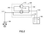
- the supply module 106 includes an SM pump 112 for pumping the urea water, an SM temperature sensor 113 for measuring a temperature of the supply module 106 (temperature of the urea water flowing through the supply module 106), a urea water pressure sensor 114 for measuring a pressure of the urea water in the supply module 106 (pressure in a discharge side of the SM pump 112), and a reverting valve 115 for switching a flow passage of the urea water to switch whether or not to supply the urea water from the urea tank 105 to the dosing valve 104 or return the urea water inside the dosing valve 104 to the urea tank 105.
- the reverting valve 115 when the reverting valve 115 is turned off, the urea water from the urea tank 105 is supplied to the dosing valve 104, and when the reverting valve 15 is turned on, the urea water inside the dosing valve 104 is returned to the urea tank 105.
- the supply module 106 suctions the urea water inside the urea tank 105 by the SM pump 112 through a liquid feed line (suction line) 116, supplies the urea water to the dosing valve 104 through a pump line (pressure line) 117, and returns surplus urea water to the urea tank 105 through a recovery line (back line) 118.
- the reverting valve 115 is switched to return the urea water inside the dosing valve 104 to the urea tank 105, so that a malfunction of the dosing valve 104 caused by crystallization of the urea water is prevented.
- control for returning the urea water inside the dosing valve 104 to the urea tank 105 in this manner will be referred to as emptying.
- the dosing valve 104 is opened in advance and the urea water inside the dosing valve 104 is returned to the urea tank 105, so that the exhaust gas (air) of the exhaust pipe 102 is suctioned from the dosing valve 104 to the urea tank 105.
- the liquid feed line 116 from inside the urea tank 105 is connected to a suction side of the SM pump 112 through the reverting valve 115.
- the SM pump 112 is connected to the dosing valve 104 through an outlet line 143 connected to the discharge side of the SM pump 112 and the reverting valve 115.
- the reverting valve 115 may be switched between a line represented by a solid line in Fig. 2 and a line represented by a broken line in Fig. 2 . This makes it possible to perform the supply of the urea water from the urea tank 105 to the dosing valve 104 and the recovery of the urea water from the dosing valve 104 to the urea tank 105.
- the recovery line 118 is connected to the pump line 117 connected to the dosing valve 104, and is configured to return the urea water to the urea tank 105.
- this line configuration is merely an example, and is not limited to the above-described configuration.
- the urea tank 105 is provided with an SCR sensor 119.
- the SCR sensor 119 includes a level sensor 120 for measuring a liquid surface height (level) of the urea water inside the urea tank 105, a temperature sensor 121 for measuring a temperature of the urea water inside the urea tank 105, and a quality sensor 122 for measuring a quality of the urea water inside the urea tank 105.
- the quality sensor 122 detects the quality of the urea water inside the urea tank 105 by detecting a concentration of the urea water or detecting whether or not a heterogeneous mixture is mixed in the urea water, for example, from a propagation speed of an ultrasonic wave or an electrical conductivity.
- a cooling line 123 for circulating cooling water for cooling the engine E is connected to the urea tank 105 and the supply module 106.
- the cooling line 123 performs heat exchange between the cooling water flowing through the urea tank 105 into the cooling line 123 and the urea water inside the urea tank 105.
- the cooling line 123 performs heat exchange between the cooling water flowing through the supply module 106 into the cooling line 123 and the urea water inside the supply module 106.
- the cooling line 123 is provided with a tank heater valve (coolant valve) 124 for switching whether or not to supply the cooling water to the urea tank 105 and the supply module 106.
- a tank heater valve coolant valve
- the cooling line 123 is also connected to the dosing valve 104, the cooling water is supplied to the dosing valve 104 regardless of the on/off of the tank heater valve 124.
- the cooling line 123 is disposed along the liquid feed line 116, the pump line 117, and the recovery line 118 through which the urea water flows.
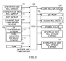
- Fig. 3 shows an input/output configuration diagram of the DCU 126.
- output signal lines to the tank heater valve 124, the SM pump 112 and the reverting valve 115 of the supply module 106, the dosing valve 104, a heater of the upstream side NOx sensor 110, and a heater of the downstream side NOx sensor 111 are connected to the DCU 126.
- the input/output of signals between the DCU 126 and the respective members may be either the input/output through separate signal lines or the input/output through a CAN (Controller Area Network).
- the DCU 126 estimates an amount of NOx in the exhaust gas based on the engine parameter signals from the ECM 125 and the temperature of the exhaust gas from the exhaust gas temperature sensor 109, and determines an amount of urea water to be injected from the dosing valve 104 based on the estimated amount of NOx in the exhaust gas and the NH 3 amount accumulated in the SCR catalyst. In addition, when the determined amount of urea water is injected by the dosing valve 104, the DCU 126 controls the dosing valve 104 and the supply module 106 based on the detection value of the upstream side NOx sensor 110 to adjust the amount of urea water to be injected from the dosing valve 104. Further, an NH 3 amount of the SCR catalyst may be estimated from, for example, the measurement values of the upstream side NOx sensor 110 and the downstream side NOx sensor 111.
- the ECM 125 transmits a DPF regeneration authorization request to the DCU 126 prior to DPF regeneration.
- the DCU 126 determines an NH 3 amount of the SCR catalyst, and transmits a DPF regeneration authorization to the ECM 125 when the NH 3 amount of the SCR catalyst is less than or equal to a prescribed value.
- the ECM 125 receives the DPF regeneration authorization and performs the DPF regeneration.
- the DCU 126 when receiving the DPF regeneration authorization request from the ECM 125, the DCU 126 stops the injection of the urea water by the dosing valve 104 in order to make the NH 3 amount of the SCR catalyst less than or equal to the prescribed value. Accordingly, the exhaust gas is purified only by the NH 3 accumulated in the SCR catalyst, and the NH3 amount of the SCR catalyst decreases.
- the DCU 126 transmits a DPF regeneration authorization to the ECM 125. Then, when receiving the DPF regeneration authorization from the DCU 126, the ECM 125 starts DPF regeneration.
- the exhaust gas purification system 100 stops the injection of the urea water by the dosing valve 104 to make the NH 3 amount of the SCR catalyst less than or equal to the prescribed value prior to the DPF regeneration, thereby preventing the occurrence of NH 3 slip caused by the release of the NH 3 accumulated in the SCR catalyst by the high-temperature exhaust gas in the DPF regeneration.
- the DCU 126 is configured to control the dosing valve 104 and the supply module 106 to inject the urea water inside the dosing valve 104 in order to remove the urea water accumulated in the dosing valve 104 when receiving the DPF regeneration authorization request from the ECM 125, and then transmit the DPF regeneration authorization to the ECM 125 when determining that the NH 3 amount of the SCR catalyst is less than or equal to the prescribed value.
- the urea water inside the dosing valve 104 can be replaced with non-high-temperature urea water from the urea tank 105.
- the exhaust gas purification system 100 is generally configured such that the dosing valve 104 is closed when a SCR catalyst temperature (exhaust gas temperature) is less than an activation temperature of the SCR catalyst (for example, 190°C in this embodiment), and the injection of the urea water from the dosing valve 104 is authorized when the exhaust gas temperature is sufficiently heated to be more than or equal to the activation temperature of the SCR catalyst.
- a SCR catalyst temperature exhaust gas temperature
- an activation temperature of the SCR catalyst for example, 190°C in this embodiment
- the injection of the urea water from the dosing valve 104 is stopped when the exhaust gas temperature is less than the activation temperature of the SCR catalyst. Since the urea water is crystallized at about 104°C to 160°C, when the exhaust gas temperature is in a temperature range of, for example, 104°C or more and less than 190°C, the urea water filled into the dosing valve 104 receiving heat of the exhaust gas in the temperature range is crystallized, so that there is a risk of causing a malfunction of the dosing valve 104.
- the DCU 126 is configured to intermittently discharge a small amount of urea water from the dosing valve 104 by opening the dosing valve 104 intermittently (for example, every three minutes), in order to prevent the adhesion of the urea water in the dosing valve 104, when the exhaust gas temperature is more than or equal to a crystallization temperature of the urea water, even when the exhaust gas temperature is less than the activation temperature of the SCR catalyst.
- the DCU 126 is configured to monitor a measurement value of the exhaust gas temperature sensor 109 and intermittently discharge a small amount of urea water from the dosing valve 104 by intermittently opening the dosing valve 104 when the measurement value is more than or equal to the crystallization temperature of the urea water and is less than the activation temperature of the SCR catalyst.
- the DCU 126 monitors the measurement value of the exhaust gas temperature sensor 109 to determine whether or not the exhaust gas temperature is more than or equal to the crystallization temperature of the urea water and is less than an injection temperature of the urea water, and intermittently discharges a small amount of urea water from the dosing valve 104 when the exhaust gas temperature is more than or equal to the crystallization temperature of the urea water and is less than the injection temperature of the urea water.
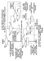
- Fig. 4 shows a flowchart summarizing the operation of the DCU 126 that has been described hitherto.
- the DCU 126 repeats an operation shown below.
- the DCU 126 determines whether or not it has received a DPF regeneration authorization request from the ECM 125 (step 400).
- the DCU 126 determines whether or not an NH 3 amount accumulated in the SCR catalyst is less than or equal to a prescribed value (step 401).
- the DCU 126 When determining in step 401 that the NH 3 amount is less than or equal to the prescribed value, the DCU 126 transmits a DPF regeneration authorization to the ECM 125 (step 402). Further, in general, since an NH 3 amount more than the prescribed value is accumulated in the SCR catalyst in order to be able to sufficiently purify the exhaust gas when an NOx amount in the exhaust gas has rapidly changed, it is determined in the first loop that the NH 3 amount is more than the prescribed value.
- the DCU 126 determines whether or not the injection of the urea water from the dosing valve 104 has been executed (step 403).
- the DCU 126 controls the dosing valve 104 and the supply module 106 to inject a small amount of urea water from the dosing valve 104 (step 404).
- Step 403 is to prevent the DPF regeneration from being retarded because a reduction of the NH 3 amount of the SCR catalyst is retarded when the injection of the urea water from the dosing valve 104 is executed a plurality of times prior to single DPF regeneration.
- the DCU 126 repeats steps 401, 403 and 405 until the NH 3 amount accumulated in the SCR catalyst becomes less than or equal to the prescribed value, and transmits the DPF regeneration authorization to the ECM 125 in step 402 when the NH 3 amount becomes less than or equal to the prescribed value.
- the DCU 126 determines whether or not the exhaust gas temperature is more than or equal to the activation temperature of the SCR catalyst (step 406).
- step 406 When determining in step 406 that the exhaust gas temperature is more than or equal to the activation temperature of the SCR catalyst, the DCU 126 starts the injection of the urea water according the NOx amount in the exhaust gas (step 407).
- the DCU 126 determines whether or not the exhaust gas temperature is out of a range more than or equal to the crystallization temperature of the urea water and less than the injection temperature of the urea water (step 408).
- step 408 When determining in step 408 that the exhaust gas temperature is out of the range more than or equal to the crystallization temperature of the urea water and less than the injection temperature of the urea water, the DCU 126 stops the injection of the urea water (step 409).
- the DCU 126 executes the injection of the urea water at predetermined periods (for example, every three minutes).
- the adhesion of the urea water in the dosing valve 104 can be prevented during the DPF regeneration, and the adhesion of the urea water in the dosing valve 104 can be prevented when the urea water is not injected by the dosing valve 104.
- the DCU 126 is configured to perform the injection of the urea water from the dosing valve 104 prior to the DPF regeneration.
- the DCU 126 may be configured to return (forcibly empty) the urea water inside the dosing valve 104 to the urea tank 105. Therefore, since the urea water inside the dosing valve 104 can be removed, the adhesion of the urea water in the dosing valve 104 during the DPF regeneration can be prevented.
- either intermittent injection or emptying is preferable.
- the DCU 126 is configured to intermittently discharge a small amount of urea water from the dosing valve 104 by intermittently opening the dosing valve 104 when the exhaust gas temperature is more than or equal to the crystallization temperature of the urea water and is less than the activation temperature of the SCR catalyst.
- the DCU 126 may be configured to forcibly execute emptying (forcible emptying) by opening the dosing valve 104, switching the reverting valve 115 of the supply module 106, and operating the SM pump 112.
- the urea water inside the dosing valve 104 can be removed prior to the crystallization of the urea water, the adhesion of the urea water in the dosing valve 104 can be prevented when the urea water is not injected by the dosing valve 104.
Landscapes
- Engineering & Computer Science (AREA)
- Chemical & Material Sciences (AREA)
- Combustion & Propulsion (AREA)
- Mechanical Engineering (AREA)
- General Engineering & Computer Science (AREA)
- Chemical Kinetics & Catalysis (AREA)
- Materials Engineering (AREA)
- Health & Medical Sciences (AREA)
- Toxicology (AREA)
- Exhaust Gas After Treatment (AREA)
- Processes For Solid Components From Exhaust (AREA)
Applications Claiming Priority (2)
| Application Number | Priority Date | Filing Date | Title |
|---|---|---|---|
| JP2010113756A JP5625475B2 (ja) | 2010-05-17 | 2010-05-17 | 排ガス浄化システム |
| PCT/JP2011/061206 WO2011145568A1 (ja) | 2010-05-17 | 2011-05-16 | 排ガス浄化システム |
Publications (2)
| Publication Number | Publication Date |
|---|---|
| EP2573342A1 true EP2573342A1 (de) | 2013-03-27 |
| EP2573342A4 EP2573342A4 (de) | 2016-08-31 |
Family
ID=44991671
Family Applications (1)
| Application Number | Title | Priority Date | Filing Date |
|---|---|---|---|
| EP11783502.5A Withdrawn EP2573342A4 (de) | 2010-05-17 | 2011-05-16 | Abgasreinigungssystem |
Country Status (5)
| Country | Link |
|---|---|
| US (1) | US9217352B2 (de) |
| EP (1) | EP2573342A4 (de) |
| JP (1) | JP5625475B2 (de) |
| CN (1) | CN102906384B (de) |
| WO (1) | WO2011145568A1 (de) |
Cited By (2)
| Publication number | Priority date | Publication date | Assignee | Title |
|---|---|---|---|---|
| EP2578831A4 (de) * | 2010-05-25 | 2016-08-31 | Isuzu Motors Ltd | Vorrichtung für selektive katalytische reduktion |
| EP3163044A1 (de) * | 2015-10-28 | 2017-05-03 | Kabushiki Kaisha Toyota Jidoshokki | Abgasreinigungsvorrichtung für einen verbrennungsmotor |
Families Citing this family (17)
| Publication number | Priority date | Publication date | Assignee | Title |
|---|---|---|---|---|
| JP5878860B2 (ja) * | 2011-12-08 | 2016-03-08 | エムエーエヌ・ディーゼル・アンド・ターボ・フィリアル・アフ・エムエーエヌ・ディーゼル・アンド・ターボ・エスイー・ティスクランド | 排気ガス浄化機能を有するターボ過給式大型2ストロークディーゼルエンジン |
| JP5609924B2 (ja) * | 2012-07-02 | 2014-10-22 | トヨタ自動車株式会社 | 内燃機関の排気浄化装置 |
| EP2930323B1 (de) * | 2012-12-07 | 2017-03-29 | Toyota Jidosha Kabushiki Kaisha | Abnormitätserkennungseinrichtung für eine abgasreinigungsvorrichtung |
| WO2015153350A1 (en) * | 2014-04-04 | 2015-10-08 | Volvo Truck Corporation | Anti-clogging device for diesel exhaust fluid supply |
| CN106512723B (zh) * | 2016-12-26 | 2023-09-19 | 大唐黑龙江发电有限公司哈尔滨第一热电厂 | 脱硝自动调节回路装置 |
| DE102017200291A1 (de) * | 2017-01-10 | 2018-07-12 | Robert Bosch Gmbh | Wassereinspritzvorrichtung, insbesondere einer Brennkraftmaschine, und Verfahren zum Betreiben einer solchen Wassereinspritzvorrichtung |
| JP6731893B2 (ja) * | 2017-07-31 | 2020-07-29 | ヤンマーパワーテクノロジー株式会社 | 作業車両 |
| CN108425723A (zh) * | 2018-03-21 | 2018-08-21 | 南京依柯卡特排放技术股份有限公司 | 在用车尾气净化DePM&NOx系统及控制方法 |
| KR102506874B1 (ko) * | 2018-07-31 | 2023-03-08 | 현대자동차주식회사 | 배기가스 후처리시스템의 우레아 분사제어방법 |
| CN110863887B (zh) * | 2018-08-28 | 2022-12-16 | 罗伯特·博世有限公司 | Dpf再生控制方法、尾气后处理系统及可读存储介质 |
| DE112020001222B4 (de) | 2019-03-14 | 2024-05-02 | Cummins Inc. | Dieselabgasfluiddosiererschutz bei kalten Umgebungstemperaturbedingungen durch Verfahren zur Zylinderabschaltung |
| CN111535903B (zh) * | 2020-05-22 | 2021-07-20 | 潍柴动力股份有限公司 | 清除反应器结晶的方法、装置和电子设备 |
| CN111894707B (zh) * | 2020-07-24 | 2021-11-23 | 东风商用车有限公司 | 一种阀组控制的尿素喷射系统及其控制方法 |
| CN112727579B (zh) * | 2020-12-31 | 2022-05-03 | 南京依柯卡特排放技术股份有限公司 | 柴油机dpf主动再生时脱除scr载体储氨的控制方法、系统及电子设备 |
| CN113356988B (zh) * | 2021-07-06 | 2022-05-24 | 南昌碳印环保科技有限公司 | 一种Urea-SCR系统尿素结晶风险的在线诊断方法 |
| SE547706C2 (en) * | 2022-08-31 | 2025-11-11 | Scania Cv Ab | Method of Diagnosing a Combustion Engine Assembly, Control Arrangement, Combustion Engine Assembly, and Vehicle |
| CN116066207B (zh) * | 2023-01-10 | 2025-01-03 | 长城汽车股份有限公司 | 氨气喷射控制系统、方法及车辆 |
Family Cites Families (14)
| Publication number | Priority date | Publication date | Assignee | Title |
|---|---|---|---|---|
| JP2000303826A (ja) | 1999-04-16 | 2000-10-31 | Isuzu Motors Ltd | ディーゼルエンジンの排ガス浄化装置 |
| JP3855781B2 (ja) | 2002-01-29 | 2006-12-13 | トヨタ自動車株式会社 | 還元剤供給装置 |
| JP4261393B2 (ja) * | 2004-03-16 | 2009-04-30 | 日野自動車株式会社 | 排気浄化装置の制御方法 |
| JP4358007B2 (ja) * | 2004-03-23 | 2009-11-04 | 株式会社日本自動車部品総合研究所 | 内燃機関の排気浄化装置 |
| DE102004054238A1 (de) * | 2004-11-10 | 2006-05-11 | Robert Bosch Gmbh | Dosiersystem sowie Verfahren zum Betreiben eines Dosiersystems |
| FR2879239A1 (fr) * | 2004-12-15 | 2006-06-16 | Inergy Automotive Systems Res | Systeme de stockage et d'injection d'un additif dans des gaz d'echappement d'un moteur |
| JP4592505B2 (ja) * | 2005-06-09 | 2010-12-01 | 三菱ふそうトラック・バス株式会社 | 排気浄化装置 |
| JP4673145B2 (ja) * | 2005-06-24 | 2011-04-20 | 株式会社サムソン | 尿素水噴射ノズルの詰まりを自動解消する脱硝装置 |
| JP4730278B2 (ja) * | 2006-10-20 | 2011-07-20 | 株式会社デンソー | エンジンの排気浄化装置 |
| JP4165896B2 (ja) * | 2007-02-19 | 2008-10-15 | ボッシュ株式会社 | 還元剤経路の詰まり判定装置及び還元剤経路の詰まり判定方法 |
| JP2009097479A (ja) | 2007-10-19 | 2009-05-07 | Bosch Corp | 還元剤供給装置の制御装置及び制御方法 |
| JP4947036B2 (ja) * | 2007-11-14 | 2012-06-06 | マツダ株式会社 | エンジンの排気浄化方法 |
| JP2010038034A (ja) * | 2008-08-05 | 2010-02-18 | Hino Motors Ltd | 排気浄化装置の制御方法 |
| JP5195277B2 (ja) * | 2008-10-24 | 2013-05-08 | マツダ株式会社 | エンジンの排気浄化装置 |
-
2010
- 2010-05-17 JP JP2010113756A patent/JP5625475B2/ja not_active Expired - Fee Related
-
2011
- 2011-05-16 WO PCT/JP2011/061206 patent/WO2011145568A1/ja not_active Ceased
- 2011-05-16 EP EP11783502.5A patent/EP2573342A4/de not_active Withdrawn
- 2011-05-16 CN CN201180024490.3A patent/CN102906384B/zh active Active
- 2011-05-16 US US13/697,912 patent/US9217352B2/en active Active
Cited By (4)
| Publication number | Priority date | Publication date | Assignee | Title |
|---|---|---|---|---|
| EP2578831A4 (de) * | 2010-05-25 | 2016-08-31 | Isuzu Motors Ltd | Vorrichtung für selektive katalytische reduktion |
| EP3163044A1 (de) * | 2015-10-28 | 2017-05-03 | Kabushiki Kaisha Toyota Jidoshokki | Abgasreinigungsvorrichtung für einen verbrennungsmotor |
| AU2016244347B2 (en) * | 2015-10-28 | 2017-11-02 | Kabushiki Kaisha Toyota Jidoshokki | Exhaust gas cleaning apparatus for internal combustion engine |
| US10107169B2 (en) | 2015-10-28 | 2018-10-23 | Kabushiki Kaisha Toyota Jidoshokki | Exhaust gas cleaning apparatus for internal combustion engine |
Also Published As
| Publication number | Publication date |
|---|---|
| CN102906384B (zh) | 2016-04-27 |
| JP5625475B2 (ja) | 2014-11-19 |
| US20130058833A1 (en) | 2013-03-07 |
| CN102906384A (zh) | 2013-01-30 |
| US9217352B2 (en) | 2015-12-22 |
| EP2573342A4 (de) | 2016-08-31 |
| JP2011241738A (ja) | 2011-12-01 |
| WO2011145568A1 (ja) | 2011-11-24 |
Similar Documents
| Publication | Publication Date | Title |
|---|---|---|
| US9217352B2 (en) | Exhaust gas purification system | |
| EP2573341B1 (de) | Scr-schmelzsteuerungssystem | |
| CN102803675B (zh) | 用于缓解柴油机排气流体沉积和关联条件的装置、系统和方法 | |
| CN102985650B (zh) | Scr系统 | |
| EP2573344B1 (de) | Gültigkeitsdiagnosesystem für einen harnstofftemperatursensor | |
| US9068487B2 (en) | Selective catalytic reduction system | |
| JP5912232B2 (ja) | Scrシステム | |
| US9127584B2 (en) | Recovery control system | |
| EP2143900B1 (de) | Abgasreinigungssystem für einen verbrennungsmotor | |
| US10309282B2 (en) | Reducing agent supply device and method for controlling reducing agent supply device | |
| CN105026711A (zh) | 尿素scr用尿素水配管闭塞检测装置 | |
| EP2573343B1 (de) | Diagnosesystem für einen temperatursensor für eine harnstofflösung | |
| JP5906637B2 (ja) | 異物除去方法及び選択還元触媒システム | |
| JP5471832B2 (ja) | Scrシステム | |
| CN105051338B (zh) | 排气净化系统及排气净化系统的控制方法 | |
| JP5617342B2 (ja) | Scrシステム | |
| EP3044433B1 (de) | Verbrennungsmotor |
Legal Events
| Date | Code | Title | Description |
|---|---|---|---|
| PUAI | Public reference made under article 153(3) epc to a published international application that has entered the european phase |
Free format text: ORIGINAL CODE: 0009012 |
|
| 17P | Request for examination filed |
Effective date: 20121211 |
|
| AK | Designated contracting states |
Kind code of ref document: A1 Designated state(s): AL AT BE BG CH CY CZ DE DK EE ES FI FR GB GR HR HU IE IS IT LI LT LU LV MC MK MT NL NO PL PT RO RS SE SI SK SM TR |
|
| DAX | Request for extension of the european patent (deleted) | ||
| RA4 | Supplementary search report drawn up and despatched (corrected) |
Effective date: 20160802 |
|
| RIC1 | Information provided on ipc code assigned before grant |
Ipc: F01N 9/00 20060101ALI20160727BHEP Ipc: F01N 3/08 20060101AFI20160727BHEP Ipc: F01N 3/02 20060101ALI20160727BHEP |
|
| STAA | Information on the status of an ep patent application or granted ep patent |
Free format text: STATUS: EXAMINATION IS IN PROGRESS |
|
| 17Q | First examination report despatched |
Effective date: 20170713 |
|
| STAA | Information on the status of an ep patent application or granted ep patent |
Free format text: STATUS: THE APPLICATION HAS BEEN WITHDRAWN |
|
| 18W | Application withdrawn |
Effective date: 20171106 |